EP0835804B1 - System for reducing ice mass on an aircraft engine - Google Patents
System for reducing ice mass on an aircraft engine Download PDFInfo
- Publication number
- EP0835804B1 EP0835804B1 EP97306078A EP97306078A EP0835804B1 EP 0835804 B1 EP0835804 B1 EP 0835804B1 EP 97306078 A EP97306078 A EP 97306078A EP 97306078 A EP97306078 A EP 97306078A EP 0835804 B1 EP0835804 B1 EP 0835804B1
- Authority
- EP
- European Patent Office
- Prior art keywords
- ice
- compressor
- wedge
- sensor
- shield
- Prior art date
- Legal status (The legal status is an assumption and is not a legal conclusion. Google has not performed a legal analysis and makes no representation as to the accuracy of the status listed.)
- Expired - Lifetime
Links
- 230000015572 biosynthetic process Effects 0.000 claims description 20
- 238000013016 damping Methods 0.000 claims description 6
- 230000001737 promoting effect Effects 0.000 claims description 3
- 238000005755 formation reaction Methods 0.000 description 17
- 239000000523 sample Substances 0.000 description 12
- 239000002184 metal Substances 0.000 description 7
- 125000006850 spacer group Chemical group 0.000 description 5
- 230000006835 compression Effects 0.000 description 3
- 238000007906 compression Methods 0.000 description 3
- 230000007704 transition Effects 0.000 description 3
- 230000003321 amplification Effects 0.000 description 1
- 230000004323 axial length Effects 0.000 description 1
- 230000003247 decreasing effect Effects 0.000 description 1
- 239000012530 fluid Substances 0.000 description 1
- 238000003199 nucleic acid amplification method Methods 0.000 description 1
- 230000036316 preload Effects 0.000 description 1
- 230000002028 premature Effects 0.000 description 1
- 230000000717 retained effect Effects 0.000 description 1
- 239000007787 solid Substances 0.000 description 1
- 230000003068 static effect Effects 0.000 description 1
- 238000006467 substitution reaction Methods 0.000 description 1
- XLYOFNOQVPJJNP-UHFFFAOYSA-N water Substances O XLYOFNOQVPJJNP-UHFFFAOYSA-N 0.000 description 1
Images


Classifications
-
- F—MECHANICAL ENGINEERING; LIGHTING; HEATING; WEAPONS; BLASTING
- F01—MACHINES OR ENGINES IN GENERAL; ENGINE PLANTS IN GENERAL; STEAM ENGINES
- F01D—NON-POSITIVE DISPLACEMENT MACHINES OR ENGINES, e.g. STEAM TURBINES
- F01D25/00—Component parts, details, or accessories, not provided for in, or of interest apart from, other groups
- F01D25/02—De-icing means for engines having icing phenomena
-
- B—PERFORMING OPERATIONS; TRANSPORTING
- B64—AIRCRAFT; AVIATION; COSMONAUTICS
- B64D—EQUIPMENT FOR FITTING IN OR TO AIRCRAFT; FLIGHT SUITS; PARACHUTES; ARRANGEMENT OR MOUNTING OF POWER PLANTS OR PROPULSION TRANSMISSIONS IN AIRCRAFT
- B64D15/00—De-icing or preventing icing on exterior surfaces of aircraft
- B64D15/16—De-icing or preventing icing on exterior surfaces of aircraft by mechanical means, e.g. pulsating mats or shoes attached to, or built into, surface
-
- F—MECHANICAL ENGINEERING; LIGHTING; HEATING; WEAPONS; BLASTING
- F02—COMBUSTION ENGINES; HOT-GAS OR COMBUSTION-PRODUCT ENGINE PLANTS
- F02C—GAS-TURBINE PLANTS; AIR INTAKES FOR JET-PROPULSION PLANTS; CONTROLLING FUEL SUPPLY IN AIR-BREATHING JET-PROPULSION PLANTS
- F02C7/00—Features, components parts, details or accessories, not provided for in, or of interest apart form groups F02C1/00 - F02C6/00; Air intakes for jet-propulsion plants
- F02C7/04—Air intakes for gas-turbine plants or jet-propulsion plants
- F02C7/047—Heating to prevent icing
-
- Y—GENERAL TAGGING OF NEW TECHNOLOGICAL DEVELOPMENTS; GENERAL TAGGING OF CROSS-SECTIONAL TECHNOLOGIES SPANNING OVER SEVERAL SECTIONS OF THE IPC; TECHNICAL SUBJECTS COVERED BY FORMER USPC CROSS-REFERENCE ART COLLECTIONS [XRACs] AND DIGESTS
- Y02—TECHNOLOGIES OR APPLICATIONS FOR MITIGATION OR ADAPTATION AGAINST CLIMATE CHANGE
- Y02T—CLIMATE CHANGE MITIGATION TECHNOLOGIES RELATED TO TRANSPORTATION
- Y02T50/00—Aeronautics or air transport
- Y02T50/60—Efficient propulsion technologies, e.g. for aircraft
Definitions
- the present invention relates, in general to jet aircraft engines and, more particularly, to a system for reducing ice mass on such engines.
- a compressor inlet temperature sensor (T25) is used to measure both total temperature and total pressure at the inlet to the compressor.
- the inlet temperature is critical for establishing the variable geometry of the stators in the compressor.
- the location of the ice accretion on the sensor with respect to the trajectory into the blades is also important. Release of this ice as a single piece or release of the "upper" or strut part of the ice can cause major damage to the compressor blades.
- FR-A-2680872 and US-A-4152938 show the use of temperature sensors combined with anti-icing devices.
- the present invention seeks to optimize engine performance by reducing the largest single ice mass that can accumulate on the compressor inlet temperature sensor which measures total temperature and total pressure at the inlet to the compressor.
- the present invention seeks to reduce the amount of ice accretion on the strut of the sensor and the amount of ice accretion on the sensing element or airfoil portion of the sensor.
- the present invention is adaptable for use with any suitable aircraft engine.
- a system for reducing ice mass on an aircraft engine having an engine compressor comprising:
- the ice shield may be separable from the sensor with which it interfaces.
- the plurality of wedge portions may comprise straight angle wedge shapes and curved surfaces to separate and minimize ice accretion in desired locations.
- the mass of each resultant ice formation can be reduced to a size that the compressor inlet blades can withstand without deformation.
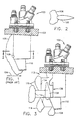
- Fig. 1 there is illustrated a side elevational view of a prior art intercompressor temperature and pressure probe 100.
- the probe 100 is mounted through a fragmentary section view of a compressor case 102, between a low pressure compressor of an aircraft engine and a high pressure compressor of an aircraft engine. Air flow is from left to right of Fig. 1, in the direction of arrow 104. Ice buildup 106 is depicted on the leading edge of the probe 100.
- the probe further comprises pressure port 108, and a complex sensing device 110 for measuring fluid temperature.
- the low pressure compressor supplies sufficient hot air to prevent the formation of ice 106.
- the engine speed is obviously decreasing.
- the low pressure compressor no longer supplies sufficient hot air to prevent the formation and buildup of ice 106.
- ice 106 typically forms during throttle back descent.
- Fig. 2 is a diagrammatic section taken along line 2-2 of Fig. 1 illustrating typical lateral extent of ice 106 formation.
- the ice 106 is typically a solid, crystalline formation, which grows out laterally, at an approximately 45° angle. This ice eventually breaks off probe 100 and travels through the downstream, high pressure compressor. The volume of ice is large enough to cause damage to the downstream compressor blades.
- the present invention comprises an ice shield 112, as a separable element that when installed, becomes integral to the existing compressor inlet temperature and pressure sensor 100.
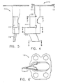
- Fig. 3 is a side elevational view of the probe 100 of Fig. 1, fitted with a preferred embodiment of ice shield 112.
- Figs. 4, 5 and 6 are side elevation, front elevation and distal end views, respectively, of the ice shield 112 of Fig. 3.
- the ice shield 112 preferably comprises disassociated features, or wedge shapes 114, which promote ice formation in multiple locations. The disassociated features have the advantage of causing smaller ice formations 116 that do not contain enough mass upon break off to damage the downstream compressor.
- Fig. 7 is a section view without background taken along line 7-7 of Fig. 4
- Fig. 8 is a section view without background taken along line 8-8 of Fig. 4.
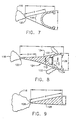
- the forward portion of the wedge is formed by straight sides 118 for a distance x. This promotes ice formation 116 only at point 120 of the wedge, rather than along both entire sides 118. This ice formation builds out triangularly because sides 118 are straight lines. If, for example, sides 118 comprised concave lines, the ice would form at the tip 120 and also at the curvaceous surfaces along sides 118. The distance as measured along x is not sufficient to promote separate ice formations and would also lead to a more abrupt transition angle as measured along the curve.
- the included angle at point 120 is preferably greater than 15°.
- the 15° angle is one optimum angle to entice the ice buildup to shed or release from the wedge.
- ice buildup per unit length of wedge appears to be equivalent for any sharp angle between 15° and 45°.
- the forward portion of the wedge is again formed by straight sides for a distance x, followed by curvaceous surfaces 124 that promotes a secondary ice formation 132 near the trailing edge of the part.
- the aspect ratio y/z for this wedge is optimized such that the ice accretion on point 122 is distinct and separate from the smaller ice masses built up on surfaces 124.
- the point 122 incorporates an included angle of 15° which will allow the ice buildup to shed under aerodynamic and vibratory forces.
- the wedge shape shown in Fig. 9 rests directly in front of the temperature sensing device 110 of Fig. 1 and incorporates both the straight line x value and the aspect ratio y/z to collect ice on point 126, but not on sides 128.
- the ice formations 116 and 132 are the result of the relatively sharp point and geometry of the wedge 114 and the aerodynamic force imparted to the ice on each side of the wedge. These aerodynamic forces will cause the ice on each side of the wedge to fracture at the point of the wedge where the ice has connected itself, but in much smaller individual masses than at tip 122.
- the 15° included angle at point 122 and the relatively sharp point at the tip 122 both cause the base of the attached ice mass 116 to be small. This base of the ice mass 116 is not wide enough to hold the ice against the aerodynamic forces and therefore releases.
- the largest single piece of ice that can strike the compressor blade from this area is much reduced. This allows the ice to move through the downstream compressor without damaging the compressor blades.
- the ice shield 112 of the present invention reduces the size of the single largest ice mass that can form on any portion of the ice shield or sensor combination. Furthermore, the ice shield 112 of the present invention reduces the total ice that accretes.
- the geometry of the wedge, as illustrated in Figs. 3-9, is such as to allow for less ice per axial length to form. This is due to the flow streamlines and minimized stagnation areas. Where the entrained water in the incoming air passes by the point of the wedge and starts to follow the streamline down the side of the wedge is where the ice will begin to accumulate.
- the ice shield is designed as a separate part to allow a sharper and longer wedge to be installed through an original, existing, small aperture in the fan frame hub structure, and inserted into the flow stream.
- a sharper and more effective wedge is achievable with the separate ice shield 112 than if the wedge were made integral to the probe 100.
- the design of the unique and separate wedge areas is such as to equalize the individual ice masses.
- the ice masses depicted by ice buildups 116 and 106 in Fig. 3 are all approximately the same size.
- the ice buildup 132 in Fig. 3 is slightly smaller. This characteristic is due to the unique shape, location, and orientations of the wedge shapes 114.
- the ice shield incorporates keys 136 in Fig. 8 that fit into keyways 138 on the modified sensor 110, as shown in Fig. 3. These keys help support the ice shield and prevent and arrest any twisting moment that may tend to occur on the wedges due to the air flow 104 in Fig. 1.
- Fig. 10 shows rubber bumper 134 installed into the ice shield at section 8-8 of Fig. 4 and also shown in cross section in Fig. 8.
- This bumper 134 is bonded to the ice shield and is squeezed or compressed when probe 100 of Fig. 3 is inserted into ice shield 112 in Fig. 3.
- This compression serves to reduce the overall vibration amplification of shield 112 in conjunction with and relative to probe 100.
- the compression also serves to preload keys 136 into keyways 138 to reduce relative motion and possible wear.
- the mounting of ice shield 112 into fan frame aperture 102 with the sensor 100 installed into the shield is shown in Fig. 14.
- the top and bottom rubber pads 140 and 142 are chemically bonded to the shield 112 and a metal spacer 144 is bonded to rubber pad 142 to form an assembly.
- Metal washers 146 one at each of four bolts, are not bonded to shield 112 and are left loose to float or move.
- the top rubber pad 140 incorporates a smaller hole than the bottom pad 142 and serves to contain or capture washers 146 so they are retained as part of the final and complete ice shield assembly.
- shield 112 is inserted first through the fan frame 102.
- sensor 100 is inserted into shield 112 and retaining means, such as bolts 148, are inserted through sensor 100 and washers 146 and through metal spacer 144, to screw into fan frame 102.
- retaining means such as bolts 148
- the rubber pads 140 and 142 are compressed with the amount of compression controlled by the height of washers 146 and the step cut on such washers, at their top.
- Sensor 100 finally comes to rest on metal spacer 144, which rests on fan frame 102. Rubber pads 140 and 142 provide vibration damping while washers 146 and spacer 144 provide for clamping of the sensor to the fan frame 102. This clamping becomes a metal to metal clamp and therefore prevents screws 148 from backing out.
- the ice shield design may incorporate a separable piece design and a mounting flange support.
- the style, size and shape of the wedge or wedges can differ greatly without departing from the scope of the invention, as long as the wedge or wedges provide distinct and separate locations for the ice buildup, thus creating smaller masses of ice, as compared to the sensor alone. Accordingly, it is intended that the invention be limited only by the scope of the appended claims.
Landscapes
- Engineering & Computer Science (AREA)
- Chemical & Material Sciences (AREA)
- Combustion & Propulsion (AREA)
- Mechanical Engineering (AREA)
- General Engineering & Computer Science (AREA)
- Aviation & Aerospace Engineering (AREA)
- Structures Of Non-Positive Displacement Pumps (AREA)
- Testing Or Calibration Of Command Recording Devices (AREA)
- Measuring Fluid Pressure (AREA)
Applications Claiming Priority (2)
| Application Number | Priority Date | Filing Date | Title |
|---|---|---|---|
| US700955 | 1996-08-21 | ||
| US08/700,955 US5752674A (en) | 1996-08-21 | 1996-08-21 | Sensor ice shield |
Publications (3)
| Publication Number | Publication Date |
|---|---|
| EP0835804A2 EP0835804A2 (en) | 1998-04-15 |
| EP0835804A3 EP0835804A3 (en) | 2001-03-21 |
| EP0835804B1 true EP0835804B1 (en) | 2003-11-05 |
Family
ID=24815499
Family Applications (1)
| Application Number | Title | Priority Date | Filing Date |
|---|---|---|---|
| EP97306078A Expired - Lifetime EP0835804B1 (en) | 1996-08-21 | 1997-08-08 | System for reducing ice mass on an aircraft engine |
Country Status (4)
| Country | Link |
|---|---|
| US (1) | US5752674A (enExample) |
| EP (1) | EP0835804B1 (enExample) |
| JP (1) | JP4072223B2 (enExample) |
| DE (1) | DE69725947T2 (enExample) |
Families Citing this family (34)
| Publication number | Priority date | Publication date | Assignee | Title |
|---|---|---|---|---|
| FR2786272B1 (fr) * | 1998-11-19 | 2001-02-09 | Auxitrol Sa | Sonde perfectionnee pour la mesure de parametres physiques d'un ecoulement de fluide |
| FR2808874B1 (fr) * | 2000-05-15 | 2002-07-26 | Auxitrol Sa | Capteur pour la mesure de parametres physiques sur un flux de fluide et notamment capteur de temperature d'air degivre |
| JP4623251B2 (ja) * | 2000-12-28 | 2011-02-02 | 株式会社Ihi | 温度・圧力コンビネーション計測器 |
| JP3749135B2 (ja) * | 2001-03-13 | 2006-02-22 | 横河電子機器株式会社 | 温度測定装置 |
| US6910659B2 (en) * | 2002-10-22 | 2005-06-28 | The Boeing Company | Method and apparatus for liquid containment, such as for aircraft fuel vessels |
| US7175136B2 (en) * | 2003-04-16 | 2007-02-13 | The Boeing Company | Method and apparatus for detecting conditions conducive to ice formation |
| JP4424617B2 (ja) * | 2003-08-20 | 2010-03-03 | ザ・ボーイング・カンパニー | 着氷状態を検出するための方法及び装置 |
| US7104502B2 (en) * | 2004-03-31 | 2006-09-12 | Rosemount Aerospace Inc. | Ice detector for improved ice detection at near freezing condition |
| US20050230553A1 (en) * | 2004-03-31 | 2005-10-20 | Rosemount Aerospace Inc. | Ice detector for improved ice detection at near freezing condition |
| US7331421B2 (en) * | 2005-03-30 | 2008-02-19 | The Boeing Company | Flow restrictors for aircraft inlet acoustic treatments, and associated systems and methods |
| US7651055B2 (en) * | 2005-05-05 | 2010-01-26 | Honeywell International Inc. | Non-streaking drainmast |
| US7313963B2 (en) * | 2006-02-28 | 2008-01-01 | General Electric Company | Isothermal de-iced sensor |
| EP2066565B1 (en) * | 2006-09-25 | 2010-11-24 | Rosemount Aerospace Inc. | Detecting ice particles |
| GB2447238B (en) * | 2007-03-07 | 2009-11-18 | Rolls Royce Plc | Method for detecting ice ingestion in a gas turbine engine |
| US8117909B1 (en) * | 2008-04-08 | 2012-02-21 | Simmonds Precision Products, Inc. | Icing resistant sensor port for a fuel tank environment |
| US8245981B2 (en) * | 2008-04-30 | 2012-08-21 | General Electric Company | Ice shed reduction for leading edge structures |
| FR2956737B1 (fr) | 2010-02-25 | 2012-03-30 | Auxitrol Sa | Sonde brise glace pour la mesure de la temperature totale d'air |
| GB201003614D0 (en) * | 2010-03-04 | 2010-04-21 | Airbus Operations Ltd | Water drain tool |
| US8752795B2 (en) * | 2010-11-23 | 2014-06-17 | John Ralph Stewart, III | Inlet nose cowl with a locally thickened fastening portion to enable an uninterrupted airflow surface |
| US8770512B2 (en) | 2011-01-14 | 2014-07-08 | Sikorsky Aircraft Corporation | Passive control of ice shedding |
| US9689755B2 (en) | 2013-10-22 | 2017-06-27 | Rosemount Aerospace Inc. | Temperature sensors |
| US10393020B2 (en) * | 2015-08-26 | 2019-08-27 | Rohr, Inc. | Injector nozzle configuration for swirl anti-icing system |
| US10203253B2 (en) | 2016-02-10 | 2019-02-12 | Rosemount Aerospace Inc. | Total air temperature probe with efficient particle pass through |
| JP6695195B2 (ja) * | 2016-03-31 | 2020-05-20 | 三菱日立パワーシステムズ株式会社 | センサカバー、センサ、及び蒸気タービン |
| US9567982B1 (en) | 2016-04-21 | 2017-02-14 | Laufer Wind Group Llc | Ice shield for tower-mounted equipment |
| US10422702B2 (en) | 2017-06-08 | 2019-09-24 | Rosemount Aerospace Inc. | Total air temperature probe with reduced icing sensor flow passage geometry |
| US10852203B2 (en) | 2018-06-15 | 2020-12-01 | Rosemount Aerospace Inc. | Total air temperature probe with concave flow path transitions to outlet |
| CN112556728B (zh) * | 2019-09-25 | 2022-07-19 | 中国航发商用航空发动机有限责任公司 | 一种防冰传感器及具有其的发动机 |
| US11879345B2 (en) * | 2020-02-28 | 2024-01-23 | Rosemount Aerospace Inc. | Pressure and temperature sensors and methods of removing ice from pressure and temperature sensors |
| US11655726B2 (en) * | 2020-02-28 | 2023-05-23 | Rosemount Aerospace Inc. | Pressure and temperature sensors and related methods |
| US11773745B2 (en) | 2020-02-28 | 2023-10-03 | Rosemount Aerospace Inc. | Pressure and temperature sensors and methods of controlling ice accretion on pressure and temperature sensors |
| US11821811B2 (en) * | 2022-02-04 | 2023-11-21 | Pratt & Whitney Canada Corp. | Fluid measurement system for an aircraft gas turbine engine and method for operating same |
| US11891902B2 (en) | 2022-04-15 | 2024-02-06 | Pratt & Whitney Canada Corp. | Fluid measurement system and method for operating same |
| US12565844B1 (en) * | 2024-09-03 | 2026-03-03 | General Electric Company | Ice-interference features for aircraft |
Family Cites Families (12)
| Publication number | Priority date | Publication date | Assignee | Title |
|---|---|---|---|---|
| US2182530A (en) * | 1937-07-24 | 1939-12-05 | Eclipse Aviat Corp | Automatic control for deicing mechanism |
| US2970475A (en) * | 1956-10-08 | 1961-02-07 | Rosemount Eng Co Ltd | Gas temperature probe |
| DE1136583B (de) * | 1961-06-02 | 1962-09-13 | Hamburger Flugzeugbau G M B H | Anordnung zum Verhueten der Eisbildung an OEffnungen von Luftfahrzeugen |
| US3329377A (en) * | 1965-10-11 | 1967-07-04 | United Aircraft Canada | Protection for aircraft engines against snow, ice and airborne particles |
| GB1181216A (en) * | 1966-07-26 | 1970-02-11 | Rosemount Eng Co Ltd | Improvements in or relating to Aerodynamic Components Mounted Externally on an Aircraft |
| US3621714A (en) * | 1969-05-13 | 1971-11-23 | Alfred R Puccinelli | Ice detector means |
| US4358075A (en) * | 1976-06-17 | 1982-11-09 | Antonov Oleg K | Anti-icing device for aerodynamic structures of aircraft |
| US4152938A (en) * | 1978-05-19 | 1979-05-08 | Karl Danninger | Aircraft temperature probe |
| GB2089035B (en) * | 1980-12-06 | 1984-10-24 | Rolls Royce | Temperature sensor |
| GB2124706B (en) * | 1982-08-04 | 1986-05-14 | Gen Electric | Gas turbine engine airflow temperature sensor |
| US5517865A (en) * | 1991-06-13 | 1996-05-21 | General Electric Company | Vortex suppression for an eductor |
| FR2680872A1 (fr) * | 1991-09-02 | 1993-03-05 | Auxitrol Sa | Sonde pour la mesure de parametres physiques d'un flux de fluide. |
-
1996
- 1996-08-21 US US08/700,955 patent/US5752674A/en not_active Expired - Lifetime
-
1997
- 1997-08-08 EP EP97306078A patent/EP0835804B1/en not_active Expired - Lifetime
- 1997-08-08 JP JP21426697A patent/JP4072223B2/ja not_active Expired - Fee Related
- 1997-08-08 DE DE69725947T patent/DE69725947T2/de not_active Expired - Lifetime
Also Published As
| Publication number | Publication date |
|---|---|
| JP4072223B2 (ja) | 2008-04-09 |
| DE69725947D1 (de) | 2003-12-11 |
| JPH10121985A (ja) | 1998-05-12 |
| US5752674A (en) | 1998-05-19 |
| EP0835804A3 (en) | 2001-03-21 |
| DE69725947T2 (de) | 2004-09-02 |
| EP0835804A2 (en) | 1998-04-15 |
Similar Documents
| Publication | Publication Date | Title |
|---|---|---|
| EP0835804B1 (en) | System for reducing ice mass on an aircraft engine | |
| US6320511B1 (en) | Ice detector configuration for improved ice detection at near freezing conditions | |
| EP0532093B1 (en) | Perforated wing panel with variable porosity | |
| US6725645B1 (en) | Turbofan engine internal anti-ice device | |
| JP3924333B2 (ja) | 複合ブレード | |
| EP0776821B1 (en) | Aircraft boundary layer control system with discharge transpiration panel | |
| US20090194633A1 (en) | Icing protection for aircraft air inlet scoops | |
| WO2002024525A3 (en) | Inflatable airfoil device | |
| CN110318883A (zh) | 一种螺旋形曲面通道的航空发动机帽罩单孔冲击换热结构 | |
| DK201170430A (en) | Blade for a rotor of a wind turbine and a wind turbine | |
| CN107054612A (zh) | 形成空气动力学翼型件的后缘并且包括鼓风系统的装置 | |
| Hutt et al. | Forward facing spike effects on bodies of different cross section in supersonic flow | |
| CN111792039A (zh) | 一种用于飞机机翼的除冰装置、系统及方法 | |
| JP5313884B2 (ja) | 誘導される抗力を小さくする装置を備える航空機 | |
| EP1967449A2 (en) | Systems and methods for reducing pressure loss of air flowing froma first area to a second area | |
| CN114080495B (zh) | 用于飞行器涡轮发动机的入口锥体和相关的飞行器涡轮发动机 | |
| US6378804B1 (en) | Aircraft wing structure profiled suspension pylon | |
| US2207242A (en) | Aircraft structure | |
| CN110466778B (zh) | 一种结冰探测器 | |
| CN110360163B (zh) | 脱冰飞机发动机 | |
| Connors et al. | Performance characteristics of several types of axially symmetric nose inlets at Mach number 3.85 | |
| Li et al. | An Experimental Study of the Dynamic Ice Accreting Process over a Rotating Aero-engine Fan Model | |
| CN216554124U (zh) | 发动机防冰装置及包括其的发动机 | |
| CN110077601A (zh) | 过冷水滴结冰探测器和混合态结冰探测器 | |
| CN113266604B (zh) | 航空发动机的进口导叶的防冰结构及进口导叶 |
Legal Events
| Date | Code | Title | Description |
|---|---|---|---|
| PUAI | Public reference made under article 153(3) epc to a published international application that has entered the european phase |
Free format text: ORIGINAL CODE: 0009012 |
|
| AK | Designated contracting states |
Kind code of ref document: A2 Designated state(s): DE FR GB IT |
|
| PUAL | Search report despatched |
Free format text: ORIGINAL CODE: 0009013 |
|
| AK | Designated contracting states |
Kind code of ref document: A3 Designated state(s): AT BE CH DE DK ES FI FR GB GR IE IT LI LU MC NL PT SE |
|
| 17P | Request for examination filed |
Effective date: 20010921 |
|
| AKX | Designation fees paid |
Free format text: DE FR GB IT |
|
| 17Q | First examination report despatched |
Effective date: 20020911 |
|
| GRAH | Despatch of communication of intention to grant a patent |
Free format text: ORIGINAL CODE: EPIDOS IGRA |
|
| GRAS | Grant fee paid |
Free format text: ORIGINAL CODE: EPIDOSNIGR3 |
|
| GRAA | (expected) grant |
Free format text: ORIGINAL CODE: 0009210 |
|
| AK | Designated contracting states |
Kind code of ref document: B1 Designated state(s): DE FR GB IT |
|
| REG | Reference to a national code |
Ref country code: GB Ref legal event code: FG4D |
|
| REF | Corresponds to: |
Ref document number: 69725947 Country of ref document: DE Date of ref document: 20031211 Kind code of ref document: P |
|
| ET | Fr: translation filed | ||
| PLBE | No opposition filed within time limit |
Free format text: ORIGINAL CODE: 0009261 |
|
| STAA | Information on the status of an ep patent application or granted ep patent |
Free format text: STATUS: NO OPPOSITION FILED WITHIN TIME LIMIT |
|
| 26N | No opposition filed |
Effective date: 20040806 |
|
| PGFP | Annual fee paid to national office [announced via postgrant information from national office to epo] |
Ref country code: GB Payment date: 20120828 Year of fee payment: 16 |
|
| PGFP | Annual fee paid to national office [announced via postgrant information from national office to epo] |
Ref country code: FR Payment date: 20120830 Year of fee payment: 16 Ref country code: IT Payment date: 20120823 Year of fee payment: 16 Ref country code: DE Payment date: 20120829 Year of fee payment: 16 |
|
| GBPC | Gb: european patent ceased through non-payment of renewal fee |
Effective date: 20130808 |
|
| PG25 | Lapsed in a contracting state [announced via postgrant information from national office to epo] |
Ref country code: DE Free format text: LAPSE BECAUSE OF NON-PAYMENT OF DUE FEES Effective date: 20140301 |
|
| REG | Reference to a national code |
Ref country code: DE Ref legal event code: R119 Ref document number: 69725947 Country of ref document: DE Effective date: 20140301 |
|
| REG | Reference to a national code |
Ref country code: FR Ref legal event code: ST Effective date: 20140430 |
|
| PG25 | Lapsed in a contracting state [announced via postgrant information from national office to epo] |
Ref country code: IT Free format text: LAPSE BECAUSE OF NON-PAYMENT OF DUE FEES Effective date: 20130808 |
|
| PG25 | Lapsed in a contracting state [announced via postgrant information from national office to epo] |
Ref country code: GB Free format text: LAPSE BECAUSE OF NON-PAYMENT OF DUE FEES Effective date: 20130808 |
|
| PG25 | Lapsed in a contracting state [announced via postgrant information from national office to epo] |
Ref country code: FR Free format text: LAPSE BECAUSE OF NON-PAYMENT OF DUE FEES Effective date: 20130902 |