EP0835769B9 - Stützvorrichtung für eine Reifenlauffläche - Google Patents
Stützvorrichtung für eine Reifenlauffläche Download PDFInfo
- Publication number
- EP0835769B9 EP0835769B9 EP97116530A EP97116530A EP0835769B9 EP 0835769 B9 EP0835769 B9 EP 0835769B9 EP 97116530 A EP97116530 A EP 97116530A EP 97116530 A EP97116530 A EP 97116530A EP 0835769 B9 EP0835769 B9 EP 0835769B9
- Authority
- EP
- European Patent Office
- Prior art keywords
- support
- top cap
- radially
- rib
- ring
- Prior art date
- Legal status (The legal status is an assumption and is not a legal conclusion. Google has not performed a legal analysis and makes no representation as to the accuracy of the status listed.)
- Expired - Lifetime
Links
Images


Classifications
-
- B—PERFORMING OPERATIONS; TRANSPORTING
- B60—VEHICLES IN GENERAL
- B60C—VEHICLE TYRES; TYRE INFLATION; TYRE CHANGING; CONNECTING VALVES TO INFLATABLE ELASTIC BODIES IN GENERAL; DEVICES OR ARRANGEMENTS RELATED TO TYRES
- B60C17/00—Tyres characterised by means enabling restricted operation in damaged or deflated condition; Accessories therefor
- B60C17/04—Tyres characterised by means enabling restricted operation in damaged or deflated condition; Accessories therefor utilising additional non-inflatable supports which become load-supporting in emergency
- B60C17/06—Tyres characterised by means enabling restricted operation in damaged or deflated condition; Accessories therefor utilising additional non-inflatable supports which become load-supporting in emergency resilient
- B60C2017/068—Tyres characterised by means enabling restricted operation in damaged or deflated condition; Accessories therefor utilising additional non-inflatable supports which become load-supporting in emergency resilient comprising springs, e.g. helical springs
Definitions
- the invention relates to a tread support device for tire, said device being used in the case of rolling of the tire under zero or low inflation pressure.
- the use of such a device says also safety and mounted inside the tire, must allow the vehicle, equipped and loaded, to continue driving despite the partial or total loss of pressure inflation, rolling continuity proving beneficial for various reasons known.
- EP 0 635 384 A corresponding to the preamble of claim 1, a device has been proposed. safety formed of two materials and comprising at least one rigid support and one elastic screed in vulcanized rubber mixture, said screed surrounding the support rigid. Between said support and said yoke is disposed a lubricant allowing the circumferential displacement of the yoke on the support, while the shape radially outside of the support crown support cooperates with the elements of reinforcement arranged in the yoke to ensure radial retention and guidance circumferential (transverse support) of the yoke on the support.
- the elements of reinforcement consist of at least one rod to which we add reinforcements reinforcement comprising at least one ply passing radially under said rod.
- High-performance safety devices are often used on vehicles having a "centralized" inflation system, that is to say a system allowing the inflation and deflation of the tire while driving, the use of a solid lubricant or pasty, but which disperses under the effects of friction and heat, causes malfunctions in the inflation system.
- the invention aims to improve the above device and to avoid as much as possible diffusion of the lubricant.
- the invention proposes to modify the meridian profiles of the radially upper face of the support crown of the support and of the face radially inner of the coping respectively, at the level of the crown edges.
- the tire tread support device in accordance with the invention and comprising at least one rigid support and an elastic yoke in vulcanized rubber mix, a lubricant, disposed between said support and said yoke, allowing circumferential movement between the support and the yoke, while the radially outer shape of the support crown of the support having two edges cooperates with the reinforcing elements arranged in the yoke to ensure the radial retention and the circumferential guidance of said yoke on the support, is characterized in that each crown rim is provided on its edge with at least one rectilinear circumferential groove in which a rib is housed circumferential disposed on the radially inner face of the part of the yoke rubber corresponding to the edge of the support crown, said rib being in contact with at least the bottom of the corresponding groove of the rim, without said rib is compressed on the bottom of said groove.
- each rib of the yoke being in contact with the bottom of the corresponding groove on the rim, the lubricant is blocked during normal driving, while allowing the rotation of the yoke around the support in rolling mode degraded (low pressure or zero pressure), lubrication being sufficient at the level grooves and the tightening of the rib on the groove being zero.
- the support crown of the support comprises a crown base and, axially on either side, two crown edges, the radially outer face of said crown bottom being further from the axis of rotation of the device than the radially outer faces of the flanges, and where else share the elastic yoke includes radially inside in each of its edges a reinforcement rod arranged axially opposite the outer face of the flange crown, each rib of the radially inner face of the yoke is advantageously located axially outside the projection on said face of the maximum axial width of the reinforcing rod.
- the efficiency of the above system is greatly improved if the space between the clevis and the support crown remains as constant as possible over the axial width, except the width corresponding to the grooves and ribs, whatever the driving conditions, i.e. at rest, in normal driving, and in driving mode degraded.
- the reinforcement turned around the two rods located in the lateral edges, is formed of cables preferably in aromatic polyamide, and is surmounted, in its central part, by a layer of cables, mutually parallel and at an angle to the circumferential direction more equal to 10 ° and preferably equal to or very close to 0 ° (i.e.
- said cables also being in aromatic or metallic polyamide.
- This variant allows to better maintain the meridian profile between the end of vulcanization of the screed and its positioning on the support, while ensuring a better distribution of forces due to centrifugal force during rolling, by shrinking the central part of said clevis.
- a reduction in the masses on the lateral edges of the screed can also be advantageously obtained by the adoption of a suitable lateral meridian profile, said profile being characterized in that it comprises, seen in cross section, a recess concave surrounded on both sides by two convex protuberances.
- the weight distribution will be optimized by the presence on the radially outer face of the yoke of at least one central groove, the lateral meridian profile which may likewise include a concave recess, allowing flexibility of the elastic screed and promoting its mountability.
- the safety device S shown in Figure 1 and intended to be mounted at the interior of a tire P, for example of dimension 14.00-20 X, is composed of three parts: a rigid metal support (1), a non-rigid elastic screed (2) intended to come into contact with the inner face of the crown of the tire P, and a annular piece (not shown) of connection with a usual removable rim, that is to say formed of at least three parts.
- the rigid support (1) is an aluminum alloy support. It is formed, seen in meridian section, of a base (not shown) surmounted radially by a disc (not shown), itself surmounted by the support crown (12), intended to receive on its radially outer face the lubricant layer (5) of the yoke (2).
- This support ring (12) has a transverse shape similar to the shape of a rim, but inverted, that is to say with a ring bottom (120) further from the axis of rotation of the device than the tops of the crown edges (122).
- the crown base (120) has a slightly convex radially outer face (121), that is to say the center of curvature of which is located on the trace XX ′ of the equatorial plane of the device and radially inside.
- the edges (122) are each provided with a circumferential and rectilinear groove (124), said groove having a depth h equal to 0.15 times e 2 , but may be between 0.10 and 0.25 times said thickness e 2 of the yoke (2), while its width measured at the top of the groove is equal to h, but can be between 0.4 h and 1.4 h.
- the groove (124) has two walls having with the radially outer face (123) of the rim (122) of the support ring (12) circular connection fillets, and are joined to a flat or circular bottom by two circular fillets .
- the parts of the radially outer faces (123) of the flanges (122), the closest to the crown bottom (120) are practically rectilinear and parallel to the axis of rotation.
- the distance, separating the point of the radially outer face (121) from the bottom (120) furthest from the axis of rotation of the straight line joining the faces (123) of the flanges (122), is equal to 22 mm, and generally at least equal to 0.25 times the thickness e 2 of the yoke (2).
- Said yoke (2) is in the form of a closed circular ring and has one face radially inner (200) which geometrically matches, -in its central part, the meridian profile of the radially outer face (121) of the support ring (12), being constantly distant from the face (121) by an amount equal to 1 mm, so as to provide maximum efficiency of the lubricant (5).
- Said face (200) is provided on each of its lateral edges of a circumferential rib (25), facing the groove (124) of the support crown (12).
- the diameter D of its generator is the same as the diameter D of the generatrix of the groove (124) closest to the axis of rotation, this which means that the tightening of the rib on the groove is zero and that there is no compression of the rib rubber.
- the axial width of the rib is less than the axial width h of the groove of the support, and said rib is located axially outside the projection t on the face (200) of the diameter, in the axial direction, of the braided rod (21).
- the yoke (2) comprises, radially inside, a layer (20) of mixture vulcanized with a low coefficient of friction with aluminum while having high mechanical resistance, in order to be able to resist surface imperfections support (1), and to foreign bodies which may possibly be inserted between said support (1) and the yoke (2).
- the rods (21), coated with a rubbery mixture, are anchor rods for a reinforcing reinforcement (23), composed of a single ply of metallic steel cables and turned outward on said rods (21) to form reversals (230).
- the rods are of the "braided” type, preferably without a central core, which allows good resistance to tension forces while allowing ovalization sufficient for easy introduction of the yoke (2), thus reinforced, in the pneumatic P.
- This frame is surmounted radially on the outside of a tread (24) of vulcanized rubber mixture, having the distinction of having losses weak hysteretics, in order to minimize the generation of heating.
- This band of bearing (24) includes two circumferential grooves (240) in the example described.
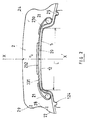
- the lateral and non-rectilinear meridian profile on each side of the yoke (2) is also the profile of the yoke (2) of the device shown in Figure 3, yoke (2) radially surmounting a rigid metal support (1).
- the support ring (12) of the support (1) has at its center a groove (125) included axially between the two flanges (122) of the support ring (12). This groove (125) is intended to receive the rib (26), central and circular, of the elastic yoke (2), a rib which is reinforced by a single rod (21) of the same type and structure as the rods (21) used. in the device shown in Figure 2.
- the groove (125) has a depth, measured in the equatorial plane XX ', between its point closest to the axis of rotation and the imaginary straight line joining the points of the flanges (122) the most distant from the axis of rotation, such that the outside radius R 4 of the rod (21) for reinforcing the rib is less than the radius of the above imaginary line, said depth e 4 being at least equal to 0 , 25 times the thickness e 2 of the yoke (2).
- Said screed (2) comprises in its radially lower part a layer of vulcanized mixture (20), identical to those of the screeds of FIGS.
- a reinforcing reinforcement (23) composed of a ply (231) of polyamide cables aromatic, having a width substantially equal to the width of the support crown for the support and passing radially under the reinforcing rod (21), and, located on either side of the equatorial plane XX ', of two narrow plies ( 232) formed, each of metallic steel cables making with the circumferential direction an angle between 0 ° and 5 °, the axial width of each of these plies (232) being equal to 0.25 times the axial width of the ply ( 231).
Landscapes
- Engineering & Computer Science (AREA)
- Mechanical Engineering (AREA)
- Tires In General (AREA)
- Support Of The Bearing (AREA)
Claims (5)
- Vorrichtung S zum Unterstützen der Lauffläche eines Luftreifens P, mit mindestens einem starren Träger (1) sowie einer elastischen Abdekkung (2) aus gummihaltiger, vulkanisierter Mischung, wobei ein Schmiermittel (5), das zwischen dem genannten Träger (1) und der genannten Abdeckung (2) angeordnet ist, die Verlagerung zwischen dem Träger (1) und der Abdeckung (2) in Umfangsrichtung gestattet, während die radial äussere Form des Auflagekranzes (12) des Trägers, die zwei Randstege (122) aufweist, mit Verstärkungselementen (21, 23) zusammenwirkt, die in der Abdeckung (2) angeordnet sind, um den radialen Halt und die Führung in Umfangsrichtung der genannten Abdeckung (2) auf dem Träger (1) sicherzustellen, dadurch gekennzeichnet, daß jeder Randsteg (122) des Auflagekranzes (12) an seinem Rand mit mindestens einer geradlinigen Umfangsnut (124) versehen ist, in der eine Umfangsrippe (25) zur Anordnung kommt, die auf der radial inneren Fläche (200) des Teiles der Abdeckung (2) aus Gummi angeordnet ist, die dem Randsteg (122) des Auflagekranzes (12) des Trägers (1) entspricht, wobei die genannte Rippe (25) mit mindestens dem Boden der entsprechenden Nut (124) des Randsteges (122) in Berührung steht, ohne daß die genannte Rippe (25) auf dem Boden der genannten Nut (124) zusammengedrückt wird.
- Vorrichtung nach anspruch 1, dadurch gekennzeichnet, daß der Auflagekranz (12) des Trägers (1) einen Kranzboden (120) und axial beiderseits zwei Kranz-Randstege (122) aufweist, wobei die radial äußere Fläche (121) des Kranzes (120) von der Drehachse der Vorrichtung weiter entfernt ist als die radial äußeren Flächen (123) der Randstege (122), und daß die elastische Abdeckung (2) radial im Inneren in jedem ihrer Ränder eine Verstärkungsschiene (21) aufweist, die axial der Außenfläche (123) des Kranzes (122) gegenüberliegend angeordnet ist, wobei jede Rippe (25) der radial inneren Fläche der Abdeckung (2) radial außerhalb der Projektion t der maximalen axialen Breite der Verstärkungsschiene (21) auf die genannte Fläche liegt.
- Vorrichtung nach Anspruch 2, deren Abdeckung (2) durch eine Verstärkungsbewehrung (23) verstäkt ist, dadurch gekennzeichnet, daß die Verstärkungsbewehrung (23) aus einer Lage (231) aus Seilen aus aromatischem Polyamid zusammengesetzt ist, die um die Schienen (21) herumgeschlagen ist, die in den seitlichen Rändern liegen, wobei über der genannten Lage (231) in ihrem mittleren Teil eine Lage (232) aus Seilen aus aromatischem Polyamid angebracht ist, die untereinander parallel sind und zur Umfangsrichtung einen Winkel bilden, der höchstens 10° beträgt und bevorzugt sehr nahe an 0° liegt.
- Vorrichtung nach einem der Ansprüche 1 bis 3, dadurch gekennzeichnet, daß die Abdeckung (2) durch eine Schiene oder Schienen (21) aus Seilen aus aromatischem Polyamid verstärkt ist.
- Vorrichtung nach einem der Ansprüche 1 bis 4, dadurch gekennzeichnet, daß das seitliche Meridianprofil der Abdeckung (2) aus einer konkaven Aussparung (28) zusammengesetzt ist, die radial auf der Innen- und Außenseite durch konvexe Ausstülpungen (27, 29) verlängert ist.
Applications Claiming Priority (2)
| Application Number | Priority Date | Filing Date | Title |
|---|---|---|---|
| FR9612346 | 1996-10-08 | ||
| FR9612346A FR2754216B1 (fr) | 1996-10-08 | 1996-10-08 | Dispositif de soutien de bande de roulement |
Publications (3)
| Publication Number | Publication Date |
|---|---|
| EP0835769A1 EP0835769A1 (de) | 1998-04-15 |
| EP0835769B1 EP0835769B1 (de) | 2002-12-11 |
| EP0835769B9 true EP0835769B9 (de) | 2004-12-01 |
Family
ID=9496526
Family Applications (1)
| Application Number | Title | Priority Date | Filing Date |
|---|---|---|---|
| EP97116530A Expired - Lifetime EP0835769B9 (de) | 1996-10-08 | 1997-09-23 | Stützvorrichtung für eine Reifenlauffläche |
Country Status (7)
| Country | Link |
|---|---|
| US (1) | US5975171A (de) |
| EP (1) | EP0835769B9 (de) |
| JP (1) | JP4034386B2 (de) |
| CA (1) | CA2215998C (de) |
| DE (1) | DE69717758T2 (de) |
| ES (1) | ES2187712T3 (de) |
| FR (1) | FR2754216B1 (de) |
Families Citing this family (8)
| Publication number | Priority date | Publication date | Assignee | Title |
|---|---|---|---|---|
| US5529884A (en) | 1994-12-09 | 1996-06-25 | Eastman Kodak Company | Backing layer for laser ablative imaging |
| MXPA03002102A (es) * | 2000-09-11 | 2004-05-24 | Dow Global Technologies Inc | Soporte de nuematico desinflado para carreras. |
| CN1326683C (zh) * | 2000-09-11 | 2007-07-18 | 陶氏环球技术公司 | 制造轮胎支承件的方法和装置 |
| EP1412207B1 (de) * | 2001-07-19 | 2008-04-16 | Société de Technologie Michelin | Notlaufeinsatz für reifen |
| KR100592992B1 (ko) * | 2003-11-24 | 2006-06-23 | 금호타이어 주식회사 | 주머니형 벨트층을 갖는 공기입 타이어 |
| FR2940770B1 (fr) * | 2009-01-08 | 2011-03-04 | Hutchinson | Dispositif de roulage a plat pour vehicule automobile et ensemble monte l'incorporant |
| US9616717B2 (en) * | 2013-06-27 | 2017-04-11 | Hutchinson, S.A. | Bead lock with wheel flange protection |
| JP7099114B2 (ja) * | 2018-07-19 | 2022-07-12 | 住友ゴム工業株式会社 | ホイール |
Family Cites Families (7)
| Publication number | Priority date | Publication date | Assignee | Title |
|---|---|---|---|---|
| US4173243A (en) * | 1975-10-17 | 1979-11-06 | Dunlop Limited | Safety tire and wheel rim assembly |
| US4183388A (en) * | 1978-07-24 | 1980-01-15 | General Motors Corporation | Run-flat tire having internal support means |
| US4327791A (en) * | 1980-09-29 | 1982-05-04 | Motor Wheel Corporation | Safety tire and wheel assembly |
| DE3501116A1 (de) * | 1985-01-15 | 1986-07-17 | Continental Gummi-Werke Ag, 3000 Hannover | Fahrzeugrad |
| JPH0481308A (ja) * | 1990-07-23 | 1992-03-16 | Bridgestone Corp | 空気入りタイヤ用中子組立体 |
| FR2707923A1 (fr) * | 1993-07-19 | 1995-01-27 | Michelin & Cie | Dispositif de soutien d'une bande de roulement de pneumatique. |
| FR2743530B1 (fr) * | 1996-01-15 | 1998-02-13 | Michelin & Cie | Ensemble pneumatique-jante pour vehicule poids-lourds |
-
1996
- 1996-10-08 FR FR9612346A patent/FR2754216B1/fr not_active Expired - Fee Related
-
1997
- 1997-09-23 ES ES97116530T patent/ES2187712T3/es not_active Expired - Lifetime
- 1997-09-23 DE DE69717758T patent/DE69717758T2/de not_active Expired - Lifetime
- 1997-09-23 EP EP97116530A patent/EP0835769B9/de not_active Expired - Lifetime
- 1997-09-25 US US08/935,095 patent/US5975171A/en not_active Expired - Lifetime
- 1997-10-03 CA CA002215998A patent/CA2215998C/fr not_active Expired - Fee Related
- 1997-10-08 JP JP27615897A patent/JP4034386B2/ja not_active Expired - Fee Related
Also Published As
| Publication number | Publication date |
|---|---|
| CA2215998C (fr) | 2005-12-06 |
| ES2187712T3 (es) | 2003-06-16 |
| DE69717758T2 (de) | 2003-09-18 |
| US5975171A (en) | 1999-11-02 |
| FR2754216A1 (fr) | 1998-04-10 |
| CA2215998A1 (fr) | 1998-04-08 |
| EP0835769A1 (de) | 1998-04-15 |
| FR2754216B1 (fr) | 1998-12-24 |
| JP4034386B2 (ja) | 2008-01-16 |
| DE69717758D1 (de) | 2003-01-23 |
| JPH10147118A (ja) | 1998-06-02 |
| EP0835769B1 (de) | 2002-12-11 |
Similar Documents
| Publication | Publication Date | Title |
|---|---|---|
| EP0748287B1 (de) | Luftreifen mit verbesserter struktur der wülste und einheit von einer reifenfelge | |
| CA2065307C (fr) | Ensemble roulant compose d'un pneumatique dont les bourrelets ont des bases tronconiques, d'une jante de montage a sieges plats, et d'adaptateurs annulaires en caoutchouc et adaptateur concu pour cet ensemble | |
| CA2070966C (fr) | Jante a fond plat pour pneumatique "poids lourds" sans chambre a air et ensemble d'une telle jante avec un pneumatique de rapport de forme inferieur a 0,80 | |
| EP0635384B1 (de) | Stützvorrichtung für eine Reifenlauffläche | |
| WO1995015863A1 (fr) | Pneumatique, jante, anneau de soutien et ensemble comprenant lesdits elements | |
| EP1098781B1 (de) | Verstärkte radialreifenwulst | |
| CH626836A5 (en) | Assembly comprising a tread strip and a wheel rim | |
| EP0835769B9 (de) | Stützvorrichtung für eine Reifenlauffläche | |
| EP1868823B1 (de) | Arretierungsring in einer anordnung zur montage eines reifens an einer fahrzeugnabe | |
| EP1144206B1 (de) | Reifen mit verbesserter wulststruktur | |
| EP2403725B1 (de) | Reifen für schwerfahrzeug | |
| EP1185425B1 (de) | Montageanordnung eines reifens auf eine nabe | |
| EP1868824B1 (de) | System zur arretierung eines montagerings an einer fahrzeugnabe | |
| CA2125297C (fr) | Pneumatique a plusieurs secteurs independants amovibles et renforces | |
| FR2812240A1 (fr) | Pneumatique avec des flancs de structure amelioree | |
| FR2788239A1 (fr) | Pneumatique avec des bourrelets de structure amelioree | |
| EP3727882A1 (de) | Reifenelement |
Legal Events
| Date | Code | Title | Description |
|---|---|---|---|
| PUAI | Public reference made under article 153(3) epc to a published international application that has entered the european phase |
Free format text: ORIGINAL CODE: 0009012 |
|
| AK | Designated contracting states |
Kind code of ref document: A1 Designated state(s): DE ES FR GB IT |
|
| 17P | Request for examination filed |
Effective date: 19981015 |
|
| AKX | Designation fees paid |
Free format text: DE ES FR GB IT |
|
| RBV | Designated contracting states (corrected) |
Designated state(s): DE ES FR GB IT |
|
| GRAG | Despatch of communication of intention to grant |
Free format text: ORIGINAL CODE: EPIDOS AGRA |
|
| 17Q | First examination report despatched |
Effective date: 20020313 |
|
| GRAG | Despatch of communication of intention to grant |
Free format text: ORIGINAL CODE: EPIDOS AGRA |
|
| GRAG | Despatch of communication of intention to grant |
Free format text: ORIGINAL CODE: EPIDOS AGRA |
|
| GRAH | Despatch of communication of intention to grant a patent |
Free format text: ORIGINAL CODE: EPIDOS IGRA |
|
| GRAH | Despatch of communication of intention to grant a patent |
Free format text: ORIGINAL CODE: EPIDOS IGRA |
|
| GRAA | (expected) grant |
Free format text: ORIGINAL CODE: 0009210 |
|
| AK | Designated contracting states |
Kind code of ref document: B1 Designated state(s): DE ES FR GB IT |
|
| REG | Reference to a national code |
Ref country code: GB Ref legal event code: FG4D Free format text: NOT ENGLISH |
|
| REF | Corresponds to: |
Ref document number: 69717758 Country of ref document: DE Date of ref document: 20030123 |
|
| GBT | Gb: translation of ep patent filed (gb section 77(6)(a)/1977) |
Effective date: 20030411 |
|
| REG | Reference to a national code |
Ref country code: ES Ref legal event code: FG2A Ref document number: 2187712 Country of ref document: ES Kind code of ref document: T3 |
|
| PLBE | No opposition filed within time limit |
Free format text: ORIGINAL CODE: 0009261 |
|
| STAA | Information on the status of an ep patent application or granted ep patent |
Free format text: STATUS: NO OPPOSITION FILED WITHIN TIME LIMIT |
|
| 26N | No opposition filed |
Effective date: 20030912 |
|
| PGFP | Annual fee paid to national office [announced via postgrant information from national office to epo] |
Ref country code: ES Payment date: 20070927 Year of fee payment: 11 |
|
| PGFP | Annual fee paid to national office [announced via postgrant information from national office to epo] |
Ref country code: GB Payment date: 20070914 Year of fee payment: 11 |
|
| GBPC | Gb: european patent ceased through non-payment of renewal fee |
Effective date: 20080923 |
|
| REG | Reference to a national code |
Ref country code: ES Ref legal event code: FD2A Effective date: 20080924 |
|
| PG25 | Lapsed in a contracting state [announced via postgrant information from national office to epo] |
Ref country code: GB Free format text: LAPSE BECAUSE OF NON-PAYMENT OF DUE FEES Effective date: 20080923 |
|
| PG25 | Lapsed in a contracting state [announced via postgrant information from national office to epo] |
Ref country code: ES Free format text: LAPSE BECAUSE OF NON-PAYMENT OF DUE FEES Effective date: 20080924 |
|
| PGFP | Annual fee paid to national office [announced via postgrant information from national office to epo] |
Ref country code: IT Payment date: 20100927 Year of fee payment: 14 |
|
| PGFP | Annual fee paid to national office [announced via postgrant information from national office to epo] |
Ref country code: DE Payment date: 20110923 Year of fee payment: 15 Ref country code: FR Payment date: 20110928 Year of fee payment: 15 |
|
| REG | Reference to a national code |
Ref country code: FR Ref legal event code: ST Effective date: 20130531 |
|
| REG | Reference to a national code |
Ref country code: DE Ref legal event code: R119 Ref document number: 69717758 Country of ref document: DE Effective date: 20130403 |
|
| PG25 | Lapsed in a contracting state [announced via postgrant information from national office to epo] |
Ref country code: DE Free format text: LAPSE BECAUSE OF NON-PAYMENT OF DUE FEES Effective date: 20130403 |
|
| PG25 | Lapsed in a contracting state [announced via postgrant information from national office to epo] |
Ref country code: IT Free format text: LAPSE BECAUSE OF NON-PAYMENT OF DUE FEES Effective date: 20120923 Ref country code: FR Free format text: LAPSE BECAUSE OF NON-PAYMENT OF DUE FEES Effective date: 20121001 |