EP0835711A2 - Fume extraction apparatus used in a welding or cutting torch - Google Patents
Fume extraction apparatus used in a welding or cutting torch Download PDFInfo
- Publication number
- EP0835711A2 EP0835711A2 EP97112348A EP97112348A EP0835711A2 EP 0835711 A2 EP0835711 A2 EP 0835711A2 EP 97112348 A EP97112348 A EP 97112348A EP 97112348 A EP97112348 A EP 97112348A EP 0835711 A2 EP0835711 A2 EP 0835711A2
- Authority
- EP
- European Patent Office
- Prior art keywords
- suction
- welding
- torch
- neck
- cutting torch
- Prior art date
- Legal status (The legal status is an assumption and is not a legal conclusion. Google has not performed a legal analysis and makes no representation as to the accuracy of the status listed.)
- Withdrawn
Links
Images

Classifications
-
- B—PERFORMING OPERATIONS; TRANSPORTING
- B23—MACHINE TOOLS; METAL-WORKING NOT OTHERWISE PROVIDED FOR
- B23K—SOLDERING OR UNSOLDERING; WELDING; CLADDING OR PLATING BY SOLDERING OR WELDING; CUTTING BY APPLYING HEAT LOCALLY, e.g. FLAME CUTTING; WORKING BY LASER BEAM
- B23K9/00—Arc welding or cutting
- B23K9/32—Accessories
- B23K9/325—Devices for supplying or evacuating shielding gas
Definitions
- the invention relates to a smoke evacuation device for welding and cutting torches with shielding gas and Air or water cooling work.
- the invention presents itself Task, the resulting flue gas at MIG welding and Cutting torches from the tip of the torch outside the Welding and cutting torch handle or the machine connection and the hose package.
- the object of the invention is achieved by arranging a Bypasses in the suction tube before the transition from the torch neck to the handle the welding and cutting torch or the Vending machine connection loosened.
- Suction pipe 2 Via the torch neck 5 with gas nozzle and all others Known burner components is a suction pipe 2 with a suction nozzle 1 and suction nozzle 3 arranged.
- Suction nozzle 1 is plugged into suction pipe 2 or screwed and ends conically in front of the gas nozzle with a short distance to each other, as can be clearly seen from Fig.1 and Fig.3.
- suction pipe 5 is firmly connected to burner neck o rotatably fitted over triple web 3a and is in suction 3-360.
- Suction nozzle 3 is fixed on the receiving ring of the torch neck 5 and is arranged to be longitudinally displaceable on the suction pipe 2.
- the burner neck receptacle 7 is inserted into the burner neck receptacle 5 and, with the arrangement of connecting and sealing bodies 10, 13 on each side and sealing surfaces 11, 14 closing against one another, the union nut 6 presses the burner neck 5 and burner neck receptacle 7 tightly against one another.
- a special embodiment of the invention is Arrangement of key way 12 in connection and sealing body 13, a corresponding in the connection and sealing body 10 Bore has, as Fig.2 shows.
- Key-way 12 is used rapid positioning of the burner in a work-related Change.
- Connection and sealing body 13 sits on the Torch neck receptacle 7.
- Suction nozzle 3 is on the suction pipe 2 can be moved to the left towards the Brennerspitze and thus exposes union nut 6. This is a Burner change is straightforward and with the support of the key-way arrangement in compliance with the previous position feasible.
- Beypass 4 arranged, through which the flue gases separated from the handle of the welding and cutting torch will.
- Beipass 4 is initially designed as a tube and goes later in a flexible, corrugated hose that light and flexible and so the work movements of the Welder is not a hindrance.
- Bypass 4 is with suction nozzle 3 also firmly connected and is with suction nozzle 3 pushed over suction pipe 2 to the union nut 6 at to expose a burner change.
- Fig.2 there are extraction nozzles 3 and bypass 4 not shown.
- a The variant according to the invention is the replacement of the suction pipe 2 through a flexible corrugated hose, preferably made of Rubber.
- Fig. 3 shows this variant.
- Suction hose 15 is analogous to suction pipe 2 in the mounting ring of torch neck 5 rotatably clamped.
- FIG. 3 is the connection the welding and cutting torch to a machine outlined.
- the O-rings 9 are sealed the rotatable and changeable connection between the suction pipe 2 or suction hose 15 and suction nozzle 3.
- the Invention is an advantageous and very practical Solution that removes the flue gas from the source during the Welding or cutting process immediately and outside of Torch handle (8) or automatic connection (8a) and hose package, without bothering the worker, removed and no specially designed handles or suction nozzles required and for both air-cooled and water-cooled Welding and cutting torches can be used without problems.
Landscapes
- Engineering & Computer Science (AREA)
- Physics & Mathematics (AREA)
- Plasma & Fusion (AREA)
- Mechanical Engineering (AREA)
- Arc Welding In General (AREA)
- Gas Burners (AREA)
Abstract
Description
Gegenstand der Erfindung ist eine Rauchgasabsaugvorrichtung für Schweiß- und Schneidbrenner, die mit Schutzgas und Luft- oder Wasserkühlung arbeiten.The invention relates to a smoke evacuation device for welding and cutting torches with shielding gas and Air or water cooling work.
Aus DE-PS 41 14 084 ist ein Griff mit Rauchgasabsaugung bekannt. Der Griff ist nicht wie bisher als Pistole gestaltet, sondern hat Röhrenform und kann dadurch die entstehenden Rauchgase von der Brennerspitze weg in den Griff des Schweiß- und Schneidbrenners führen und über das Schlauchpaket entsorgen. Eine andere Lösung offenbart EP-A2-502 421. Dabei werden Brennerhals und Gasdüse von einem Saugrohr umgeben, welches in Gasdüsennähe als Absaugdüse besonders ausgestaltet ist. Auch hier wird das Rauchgas durch den Griff des Schweiß- und Schneidbrenners und das Schlauchpaket entsorgt. Bei allen bekannten Lösungen wird versucht das Rauchgas vom Entstehungsort, der Schweißnaht, über ein Absaugrohr, das über dem Brenner mit Gasdüse angeordnet ist, in den Griff des Schweiß- und Schneidbrenners und von da über das Schlauchpaket abzuführen.From DE-PS 41 14 084 is a handle with smoke evacuation known. The handle is not as a pistol as before designed, but has a tubular shape and can therefore smoke gases from the burner tip into the Pass the handle of the welding and cutting torch and over the Discard the hose package. Another solution is disclosed in EP-A2-502 421. The torch neck and gas nozzle are combined by one Surround the suction pipe, which is close to the gas nozzle as a suction nozzle is specially designed. Here too the flue gas through the handle of the welding and cutting torch and that Hose package disposed of. With all known solutions tries the flue gas from the place of origin, the weld seam, via a suction pipe that is above the burner with gas nozzle is arranged in the handle of the welding and cutting torch and lead away from there via the hose package.
Vor diesem Hintergrund stellt sich die Erfindung die Aufgabe, das entstehende Rauchgas bei MIG-Schweiß- und Schneidbrennern von der Brennerspitze außerhalb des Schweiß- und Schneidbrennergriffes bzw. des Automatenanschlusses und des Schlauchpaketes abzuführen.Against this background, the invention presents itself Task, the resulting flue gas at MIG welding and Cutting torches from the tip of the torch outside the Welding and cutting torch handle or the machine connection and the hose package.
Die Aufgabe der Erfindung wird durch Anordnen eines Beipasses in das Absaugrohr vor dem Übergang Brennerhals-Griff des Schweiß- und Schneidbrenners oder den Automatenanschluß gelöst.The object of the invention is achieved by arranging a Bypasses in the suction tube before the transition from the torch neck to the handle the welding and cutting torch or the Vending machine connection loosened.
Die Erfindung wird anhand von Zeichnungen näher erläutert. Dabei zeigen:
- Fig.1
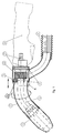
- Schnittdarstellung eines Schweiß- und Schneidbrenners
- Fig.2
- Schnittdarstellung des Details A aus Fig.1
- Fig.3
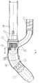
- Schnittdarstellung eines Automatenbrenners.
- Fig. 1
- Sectional view of a welding and cutting torch
- Fig. 2
- Sectional view of detail A from Fig.1
- Fig. 3
- Sectional view of an automatic burner.
Über den Brennerhals 5 mit Gasdüse und allen anderen
bekannten Brennerbauteile ist ein Absaugrohr 2 mit Absaugdüse
1 und Absaugstutzen 3 angeordnet. Absaugdüse 1 wird
auf Absaugrohr 2 gesteckt oder geschraubtgesteckt und
endet konisch vor der Gasdüse mit einem geringen Abstand
zueinander, wie aus Fig.1 und Fig.3 gut zu erkennen ist.Via the
Absaugrohr 2 ist mit Brennerhals 5 fest verbunden über
Dreifachsteg 3a und wird in Absaugstutzen 3 drehbar bis
360o gesteckt. Absaugstutzen 3 ist auf dem Aufnahmering des
Brennerhalses 5 fest und auf dem Absaugrohr 2 längs
verschiebbar angeordnet. In die Brennerhalsaufnahme 7 wird
Brennerhals 5 gesteckt und mit der Anordnung von Anschluß- und
Dichtkörpern 10,13 auf jeder Seite und gegeneinander
abschließende Dichtflächen 11,14 preßt Überwurfmutter 6
Brennerhals 5 und Brennerhalsaufnahme 7 dicht aneinander.2
Eine besondere Ausgestaltung der Erfindung ist die
Anordnung von Key-way 12 im Anschluß- und Dichtkörper 13,
der im Anschluß- und Dichtkörper 10 eine entsprechende
Bohrung hat, wie Fig.2 zeigt. Key-way 12 dient der
schnellen Positionierung des Brenners bei einem arbeitsbedingten
Wechsel. Anschluß- und Dichtkörper 13 sitzt auf der
Brennerhalsaufnahme 7. Absaugstutzen 3 ist auf dem Absaugrohr
2 nach links in Richtung Brennerspitze verschiebbar
und legt somit Überwurfmutter 6 frei. Dadurch ist ein
Brennerwechsel unkompliziert und mit Unterstützung der Key-way-Anordnung
unter Einhaltung der vorherigen Position
durchführbar. Am Absaugstutzen 3 ist erfindungsgemäß ein
Beipaß 4 angeordnet, über den die Rauchgase getrennt von
der Griffschale des Schweiß- und Schneidbrenners abgezogen
werden. Beipaß 4 ist anfangs als Rohr ausgebildet und geht
später über in einen flexiblen, gewellten Schlauch, der
leicht und beweglich und so den Arbeitsbewegungen des
Schweißers nicht hinderlich ist. Beipaß 4 ist mit Absaugstutzen
3 auch fest verbunden und wird mit Absaugstutzen 3
über Absaugrohr 2 geschoben, um die Überwurfmutter 6 bei
einem Brennerwechsel freizulegen. In Fig.2 sind Absaugstutzen
3 und Beipaß 4 nicht mit dargestellt. Eine
erfindungsgemäße Variante ist der Ersatz des Absaugrohres 2
durch einen flexiblen gewellten Schlauch, bevorzugt aus
Gummi. Diese Variante zeigt Fig.3. Absaugschlauch 15 wird
analog Absaugrohr 2 in den Aufnahmering von Brennerhals 5
drehbar geklemmt. Die freie Beweglichkeit von Absaugrohr 2
oder Absaugschlauch 15 im Absaugstutzen 3 schafft die für
den Schweißer notwendige Bewegungsfreiheit beim Schweißen
und beugt zeitigem Ermüden vor. In Fig.3 ist der Anschluß
des Schweiß- und Schneidbrenners an einen Automaten
skizziert. In jeder Variante dichten angeordnete O-Ringe 9
die dreh- und wechselbare Verbindung zwischen Absaugrohr 2
oder Absaugschlauch 15 und Absaugstutzen 3 sicher ab. Die
Erfindung ist eine vorteilhafte und sehr praktikable
Lösung, die das Rauchgas vom Entstehungsort während des
Schweiß- oder Schneidprozesses sofort und außerhalb vom
Brennergriff (8) oder Automatenanschluß (8a) und Schlauchpaket,
ohne die Arbeitskraft zu belästigen, entfernt und
dabei keine besonders ausgebildeten Griffe oder Absaugdüsen
erfordert und sowohl bei luft- als auch bei wassergekühlten
Schweiß- und Schneidbrennern problemlos anwendbar ist.A special embodiment of the invention is
Arrangement of
Claims (5)
das Absaugrohr (2) mit Brennerhals (5) im Absaugstutzen (3) im Bereich von 360o drehbar vor der Griffschale (8) oder dem Automatenanschluß angeordnet ist, wobei Absaugstutzen (3) über Überwurfmutter (6) angeordnet ist.Welding and cutting torch, in air or water-cooled design, with flue gas extraction, consisting of an extraction pipe arranged above the torch neck and then an extraction nozzle, characterized in that
the suction pipe (2) with burner neck (5) in the suction nozzle (3) can be rotated in the range of 360 o in front of the handle (8) or the machine connection, suction nozzle (3) being arranged via a union nut (6).
an Absaugstutzen (3) Beipass (4) angeordnet ist, der mit Absaugstutzen (3) fest verbunden und zusammen mit Absaugstutzen (3) längs verschiebbar ist.Welding and cutting torch according to claim 1, characterized in that
on the suction nozzle (3) bypass (4) is arranged, which is firmly connected to the suction nozzle (3) and can be moved longitudinally together with the suction nozzle (3).
Beipass (4) als flexibler gewellter Schlauch aus Gummi ausgebildet ist.Welding and cutting torch according to claim 1 and 2, characterized in that
Bypass (4) is designed as a flexible corrugated hose made of rubber.
Absaugrohr (2) mit Brennerhals (5) fest verbunden und beide mittels Überwurfmutter (6) lösbar an der Brennerhalsaufnahme (7) angeordnet sind.Welding and cutting torch according to claim 1, characterized in that
Suction tube (2) is firmly connected to the torch neck (5) and both are detachably arranged on the torch neck receptacle (7) by means of a union nut (6).
auf dem Brennerhals (5), vor dem Aufnahmering, ein Mehrfach-Steg (3a) angeordnet ist, der in das Absaugrohr (2) greift.Welding and cutting torch according to claim 1, characterized in that
on the burner neck (5), in front of the receiving ring, a multiple web (3a) is arranged, which engages in the suction pipe (2).
Applications Claiming Priority (2)
| Application Number | Priority Date | Filing Date | Title |
|---|---|---|---|
| DE29617751U | 1996-10-12 | ||
| DE29617751U DE29617751U1 (en) | 1996-10-12 | 1996-10-12 | Welding and cutting torch with smoke evacuation device |
Publications (2)
| Publication Number | Publication Date |
|---|---|
| EP0835711A2 true EP0835711A2 (en) | 1998-04-15 |
| EP0835711A3 EP0835711A3 (en) | 1998-09-02 |
Family
ID=8030489
Family Applications (1)
| Application Number | Title | Priority Date | Filing Date |
|---|---|---|---|
| EP97112348A Withdrawn EP0835711A3 (en) | 1996-10-12 | 1997-07-18 | Fume extraction apparatus used in a welding or cutting torch |
Country Status (3)
| Country | Link |
|---|---|
| EP (1) | EP0835711A3 (en) |
| CZ (1) | CZ266997A3 (en) |
| DE (1) | DE29617751U1 (en) |
Cited By (6)
| Publication number | Priority date | Publication date | Assignee | Title |
|---|---|---|---|---|
| EP2298485A1 (en) | 2009-09-10 | 2011-03-23 | TBI Industries GmbH | Suction device for robotic welding torches |
| CN113262591A (en) * | 2020-10-16 | 2021-08-17 | 江苏归舜环保科技有限公司 | Glass fiber reinforced plastic heat exchange device for welding smoke purifier |
| WO2022233483A1 (en) | 2021-05-06 | 2022-11-10 | Alexander Binzel Schweisstechnik Gmbh & Co. Kg | Combined extraction/shielding gas nozzle of an arc welding torch with a non-consumable electrode and torch body comprising a combined extraction/shielding gas nozzle |
| DE102021111790A1 (en) | 2021-05-06 | 2022-11-10 | Alexander Binzel Schweisstechnik Gmbh & Co. Kg | Combined suction and shielding gas nozzle of an arc welding torch with consumable electrode and torch neck with a combined suction and shielding gas nozzle |
| DE202024102116U1 (en) | 2024-03-11 | 2024-06-18 | Autogen-Ritter, Johann Ritter Nachfolger Gesellschaft mbH | Welding and/or cutting torch with integrated exhaust gas flow chamber |
| DE102023123701B3 (en) | 2023-09-04 | 2024-09-12 | Alexander Binzel Schweisstechnik Gmbh & Co. Kg | Burner with movable suction pipe |
Citations (3)
| Publication number | Priority date | Publication date | Assignee | Title |
|---|---|---|---|---|
| FR2306779A1 (en) * | 1975-04-11 | 1976-11-05 | Charlin Gerard | Arc welding torch provided with inert gas shield - and a consumable electrode wire, plus a fume extn. hood |
| US4496823A (en) * | 1982-11-22 | 1985-01-29 | Bob Mann & Associates Incorporated | Multiple passage conduit for fume extracting welding gun |
| CA1181967A (en) * | 1982-02-22 | 1985-02-05 | Mark A. Huza | Welding gun |
-
1996
- 1996-10-12 DE DE29617751U patent/DE29617751U1/en not_active Expired - Lifetime
-
1997
- 1997-07-18 EP EP97112348A patent/EP0835711A3/en not_active Withdrawn
- 1997-08-22 CZ CZ972669A patent/CZ266997A3/en unknown
Patent Citations (3)
| Publication number | Priority date | Publication date | Assignee | Title |
|---|---|---|---|---|
| FR2306779A1 (en) * | 1975-04-11 | 1976-11-05 | Charlin Gerard | Arc welding torch provided with inert gas shield - and a consumable electrode wire, plus a fume extn. hood |
| CA1181967A (en) * | 1982-02-22 | 1985-02-05 | Mark A. Huza | Welding gun |
| US4496823A (en) * | 1982-11-22 | 1985-01-29 | Bob Mann & Associates Incorporated | Multiple passage conduit for fume extracting welding gun |
Cited By (11)
| Publication number | Priority date | Publication date | Assignee | Title |
|---|---|---|---|---|
| EP2298485A1 (en) | 2009-09-10 | 2011-03-23 | TBI Industries GmbH | Suction device for robotic welding torches |
| CN113262591A (en) * | 2020-10-16 | 2021-08-17 | 江苏归舜环保科技有限公司 | Glass fiber reinforced plastic heat exchange device for welding smoke purifier |
| WO2022233483A1 (en) | 2021-05-06 | 2022-11-10 | Alexander Binzel Schweisstechnik Gmbh & Co. Kg | Combined extraction/shielding gas nozzle of an arc welding torch with a non-consumable electrode and torch body comprising a combined extraction/shielding gas nozzle |
| DE102021111790A1 (en) | 2021-05-06 | 2022-11-10 | Alexander Binzel Schweisstechnik Gmbh & Co. Kg | Combined suction and shielding gas nozzle of an arc welding torch with consumable electrode and torch neck with a combined suction and shielding gas nozzle |
| DE102021111780A1 (en) | 2021-05-06 | 2022-11-10 | Alexander Binzel Schweisstechnik Gmbh & Co. Kg | Combined suction and shielding gas nozzle of an arc welding torch with non-consumable electrode and torch body with a combined suction and shielding gas nozzle |
| WO2022233484A1 (en) | 2021-05-06 | 2022-11-10 | Alexander Binzel Schweisstechnik Gmbh & Co. Kg | Combined extraction/shielding gas nozzle of an arc welding torch with a consumable electrode and torch neck having a combined extraction/shielding gas nozzle |
| DE102021111790A8 (en) | 2021-05-06 | 2024-01-18 | Alexander Binzel Schweisstechnik Gmbh & Co. Kg | Combined suction shielding gas nozzle of an arc welding torch with consumable electrode and torch neck with a combined suction shielding gas nozzle |
| DE102021111780B4 (en) | 2021-05-06 | 2024-03-28 | Alexander Binzel Schweisstechnik Gmbh & Co. Kg | Combined suction protective gas nozzle of an arc welding torch with non-consumable electrode and torch body with a combined suction protective gas nozzle |
| DE102021111790B4 (en) | 2021-05-06 | 2024-07-04 | Alexander Binzel Schweisstechnik Gmbh & Co. Kg | Combined extraction and shielding gas nozzle of an arc welding torch with a consumable electrode and torch neck with a combined extraction and shielding gas nozzle |
| DE102023123701B3 (en) | 2023-09-04 | 2024-09-12 | Alexander Binzel Schweisstechnik Gmbh & Co. Kg | Burner with movable suction pipe |
| DE202024102116U1 (en) | 2024-03-11 | 2024-06-18 | Autogen-Ritter, Johann Ritter Nachfolger Gesellschaft mbH | Welding and/or cutting torch with integrated exhaust gas flow chamber |
Also Published As
| Publication number | Publication date |
|---|---|
| DE29617751U1 (en) | 1996-11-28 |
| EP0835711A3 (en) | 1998-09-02 |
| CZ266997A3 (en) | 1999-04-14 |
Similar Documents
| Publication | Publication Date | Title |
|---|---|---|
| EP0835711A2 (en) | Fume extraction apparatus used in a welding or cutting torch | |
| EP3017901B1 (en) | Tig welding torch with arc-shaped guide | |
| EP0676256B1 (en) | Welding device for thin plates travelling under a stationary water-cooled welding head | |
| DE2947284A1 (en) | WELDING TOOL | |
| DE2158051C3 (en) | Suction device | |
| DE2733372C2 (en) | Autogenous welding and / or cutting torch | |
| DE2231037C3 (en) | Device for arc welding with a consumable electrode under protective gas | |
| DE19531723A1 (en) | Skirt for attachment to gas nozzle of gas-shielded arc welding gun | |
| DE102023123701B3 (en) | Burner with movable suction pipe | |
| DD146156B1 (en) | DEVICE FOR WELDING BURNERS FOR WELDING EXTRACTION IN PROTECTIVE GASS WELDING | |
| DE2243924A1 (en) | Gas shielded electric arc welding gun - is simply adaptable and manipulatable | |
| DE2827403C2 (en) | Device to increase the service life of gas primers with a porous graphite rinsing head | |
| EP1419848A3 (en) | Welding device and process for welding | |
| DE10159459A1 (en) | Pressing device used for welding two or more metal sheets together comprises a conical sleeve arranged on a welding lens of a welding beam and freely rotating about an axis which is inclined about an angle to the axis of the welding beam | |
| DE2401425A1 (en) | Suction head for removing noxious gases from a welding area - attached above electrode nozzle of welding torch | |
| DE4236236A1 (en) | Extractor for removing welding fumes - with nozzle attached to robot torch or head and hose connected to fan | |
| DD222228B1 (en) | PROTECTIVE GAS WELDING BURNER FOR AUTOMATIC WELDING SYSTEMS | |
| DD262382A1 (en) | DEVICE FOR SUCTION WHEN WELDING GASES | |
| DD211985A1 (en) | weld pool | |
| EP1537936A1 (en) | Gas shielding arc welding apparatus with a back draught security device | |
| DD235214A1 (en) | METHOD AND DEVICE FOR CLEANING WELDING BURNERS | |
| DE1565221C3 (en) | Arc gouging torch | |
| DE10139634C1 (en) | Laser welding device has protection gas supplied via ring facilitating free rotation of welding head | |
| DE8422113U1 (en) | Device for automatically changing an electrode cap on resistance welding equipment | |
| DE19619693A1 (en) | Gas shielded arc welding torch nozzle |
Legal Events
| Date | Code | Title | Description |
|---|---|---|---|
| PUAI | Public reference made under article 153(3) epc to a published international application that has entered the european phase |
Free format text: ORIGINAL CODE: 0009012 |
|
| AK | Designated contracting states |
Kind code of ref document: A2 Designated state(s): AT BE CH DE DK ES FI FR GB GR IE IT LI LU MC NL PT SE |
|
| PUAL | Search report despatched |
Free format text: ORIGINAL CODE: 0009013 |
|
| AK | Designated contracting states |
Kind code of ref document: A3 Designated state(s): AT BE CH DE DK ES FI FR GB GR IE IT LI LU MC NL PT SE |
|
| AKX | Designation fees paid | ||
| RBV | Designated contracting states (corrected) | ||
| STAA | Information on the status of an ep patent application or granted ep patent |
Free format text: STATUS: THE APPLICATION IS DEEMED TO BE WITHDRAWN |
|
| 18D | Application deemed to be withdrawn |
Effective date: 19990303 |