EP0835476B1 - Optisches system - Google Patents
Optisches system Download PDFInfo
- Publication number
- EP0835476B1 EP0835476B1 EP97908467A EP97908467A EP0835476B1 EP 0835476 B1 EP0835476 B1 EP 0835476B1 EP 97908467 A EP97908467 A EP 97908467A EP 97908467 A EP97908467 A EP 97908467A EP 0835476 B1 EP0835476 B1 EP 0835476B1
- Authority
- EP
- European Patent Office
- Prior art keywords
- polarization
- optical system
- polarizing element
- light
- picture display
- Prior art date
- Legal status (The legal status is an assumption and is not a legal conclusion. Google has not performed a legal analysis and makes no representation as to the accuracy of the status listed.)
- Expired - Lifetime
Links
Images


Classifications
-
- G—PHYSICS
- G02—OPTICS
- G02B—OPTICAL ELEMENTS, SYSTEMS OR APPARATUS
- G02B5/00—Optical elements other than lenses
- G02B5/30—Polarising elements
- G02B5/3083—Birefringent or phase retarding elements
Definitions
- the invention relates to an optical system comprising a polarizing element in the form of a layer comprising an isotropic material having a refractive index n i and an anisotropic material having refractive indices n a,e and n a,o , in which n i is substantially equal to n a,e or n a,o .
- the invention also relates to a flat picture display device and to an image projection device provided with such an optical system.
- a polarizing element as described in the optical system of the type described in the opening paragraph is known from, for example the publication: "Polarizer” in Research Disclosure, July 1993, no. 35117, pp. 452-453.
- the polarizer described in this publication comprises a layer of birefringent material which is present between two glass plates and in which glass granules are distributed.
- the glass granules have a refractive index which is equal to the ordinary refractive index of the birefringent material. Consequently, an unpolarized light beam incident on the polarizer will fall apart into an ordinary and an extraordinary beam component. Since the glass granules have a refractive index which is equal to the ordinary refractive index of the birefringent material, the ordinary beam component will be passed, whereas the extraordinary beam component will be diffused in the layer and consequently disappears from the light path.
- a drawback of such a polarizer is that substantially half the intensity of an incident light beam is lost because the beam component having the unwanted direction of polarization is removed from the light path.
- US-A-5,422,756 does not disclose a layer as recited in the characterising portion of Claim 1, but it describes an optical system which includes all the other features of Claim 1. It uses a polarizing element which is in the form of a repeating stack of layers of two isotropic materials having refractive indices which are not substantially the same, and the means for retroreflection are constituted by a flat element which is provided with a relief structure on a side facing the polarizing element. It also uses means for polarization conversion which are constituted by a depolarizer and a reflector.
- the operation of the optical system is based on the fact that, due to the polarizing element, there is a separation of polarization between the ordinary and extraordinary radiation, while one of the polarization components is passed substantially undeflected.
- the complementary polarization component is diffused in such a way that retroreflection of this component is made possible, instead of this component being arbitrarily diffused from the light path. In this way it is possible to recuperate the diffused polarization component.
- the means for retroreflecting light with the diffused polarization direction may be implemented in different manners.
- a first embodiment of the optical system according to the invention is characterized in that the anisotropic material is formed by particles for which it holds that: 0.5 ⁇ ⁇ ⁇ ⁇ 10 ⁇ in which ⁇ is the dimension of the particles in the anisotropic direction, and in that it holds for the distance d between the particles that: 10 ⁇ > d > 0.5 ⁇ and for the refractive indices: 0.3 >
- the diffused polarization component will undergo retroreflection.
- the means are comprised in the layer with particles.
- a second embodiment of the optical system according to the invention is characterized in that the means for retroreflection are constituted by a flat element which is provided with a relief structure on a side facing the polarizing element, this element having a reflective effect for light rays with an angle of incidence which is larger than a critical angle ⁇ c .
- the dimensions of the particles and their mutual distance are now less important.
- the extraordinary light rays should now be deflected only at such an angle with respect to the normal on the polarizing element that they are incident on the flat element at an angle ⁇ which is larger than ⁇ c .
- ⁇ c is the minimum angle for which reflection occurs. For angles which are smaller than this critical angle, there is transmission. For angles which are larger than this critical angle, the light rays will be back-reflected.
- a further embodiment of the optical system according to the invention is characterized in that 0 ⁇
- the polarizing element behaves as a diffuser for the undeflected transmitted radiation so that a homogeneous light distribution on the surface of the polarizing element is obtained.
- Diffusing one of the polarization components in a controlled way provides the possibility of recuperating the diffused polarization component so that it can be converted into light having a direction of polarization which corresponds to the non-diffused polarization component. In this way, an unpolarized beam may be converted substantially completely into a beam having the same direction of polarization without a considerable quantity of the incident light beam getting lost.
- a further embodiment of the optical system according to the invention is characterized in that the optical system further comprises means for at least partly converting the diffused polarization component into a complementarily polarized component.
- a further embodiment of the optical system according to the invention is characterized in that the means for polarization conversion are constituted by a depolarizer and a reflector.
- a reflector preceded by a depolarizer is present on the side located opposite the side on which the light to be polarized is incident.
- the retroreflected light will be depolarized and subsequently sent by the reflector to the polarizing element again.
- half of this light will have obtained the direction of polarization which is suitable for the polarizing element and will consequently be transmitted by the polarizing element.
- the retroreflected light is recuperated and at least partly converted into light having a direction of polarization which corresponds to that of the undiffused component.
- optical system as described hereinbefore may be used in flat picture display devices operating with peripheral lighting, background lighting or ambient light.
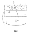
- the illumination system 1 shown diagrammatically in Fig. 1 includes an optical system comprising a polarizing element 3, and further includes a radiation source 6.
- the polarizing element 3 is constituted by a layer comprising an isotropic material having a refractive index n i and an anisotropic material having refractive indices n a,e and n a,o .
- the extraordinary polarization component will undergo a refractive index difference and be diffused in the layer. If no extra measures are taken, the diffused component will be diffused arbitrarily and disappear from the light path so that substantially half the intensity supplied by the light source is lost. To prevent this, the present invention ensures that one of the polarization components diffused in a controlled manner so that it is possible to recuperate it and subsequently at least partly convert it into light having a direction of polarization which corresponds to that of the undiffused polarization component.
- a first possibility is to implement the polarizing element 3 as a layer with particles 4 or a layer with clusters of particles satisfying the following conditions: 0.5 ⁇ ⁇ ⁇ ⁇ 10 ⁇ 10 ⁇ > d > 0.5 ⁇ in which ⁇ is the dimension of the particles or of a cluster of particles in the anisotropic direction and d is the distance between the particles or the clusters, while it holds for the refractive indices that: 0.3 >
- the diffused polarization component When these conditions are satisfied, the diffused polarization component will be back-reflected towards the radiation source 6, in other words, it will undergo retroreflection.
- the optical system comprises a polarizing element 3 and a flat element 5 arranged on the side of the polarizing element 3 facing away from the radiation source, which flat element has a relief structure 9 on a side 7 facing the polarizing element 3.
- the relief structure 9 may be, for example a prism foil.
- the flat element 5 will function as a reflecting element.
- the reflective effect of the relief structure is determined by the apex angles of the prisms. In fact, they determine the angle ⁇ c , in other words, the angle from which reflection occurs.
- Light which is incident at an angle smaller than ⁇ c is passed by the relief structure, whereas there is reflection on the relief structure for angles of incidence which are larger than ⁇ c .
- the ordinary polarization component will be passed and the extraordinary polarization component will be reflected.
- the extraordinary beam should be incident on the flat element 5 at an angle which is larger than ⁇ c .
- the angle at which the deflected component will leave the polarizing element 3 is determined, inter alia by the extent of birefringence of the anisotropic material.
- the optical system may be further provided with a depolarizing element 11 and a reflector 13.
- the depolarizing element 11 may be, for example a birefringent foil.
- the extraordinary polarization component is converted by this element into an unpolarized beam so that approximately half of this beam acquires a direction of polarization which can be passed undeflected by the polarizing element 3.
- the reflector 13 ensures that the depolarized light reaches the polarizing element 3 again.
- the depolarizing element 11 and the reflector 13 may be implemented as a single element combining the two functions. Such an element should then be present on the side of the radiation source facing away from the polarizing element.
- both the ordinary polarization component and the extraordinary polarization component may be diffused in the layer.
- the refractive indices n a,o and n a,e of the anisotropic material determine which of the two polarization components will be diffused.
- the polarizing element 3 may consist of, for example a layer of anisotropic material in which isotropic particles are dispersed as described, for example in the publication: "Polarizer” in Research Disclosure, July 1993, no. 35117, pp. 452-453.
- the layer may alternatively consist of isotropic material in which anisotropic particles are dispersed.
- Fig. 1 also illustrates the radiation path of a light beam b.
- An unpolarized beam b is incident on the depolarizing element 11 so that the beam remains unpolarized.
- the ordinary beam component b 1 and the extraordinary beam component b 2 are separated from each other in the polarizing element 3.
- the ordinary beam component b 1 is passed undeflected.
- the extraordinary beam component b 2 is reflected in a multiple way so as to be ultimately sent towards the radiation source.
- Fig. 2 also shows a depolarizing element 11 and a reflector 13.
- the ordinary beam component b 1 of a light beam b is passed undeflected, whereas the extraordinary beam component b 2 is deflected with respect to the normal on the polarizing element in such a way that it is incident at an angle larger than ⁇ c on the flat element 5 and is reflected thereby. Consequently, this beam component will again be deflected in the polarizing element so that this component is sent towards the radiation source 6.
- the component b 2 is depolarized by the depolarizing element 11 and reflected by the reflector 13. Upon arrival at the polarizing element 3, substantially half this component will have the desired direction of polarization and consequently be passed undeflected.
- the polarizing element 3 preferably also acts as a diffuser for the desired polarization component, in this example, the ordinary polarization component. This can be achieved by ensuring that: 0 ⁇
- a first application relates to a flat picture display device.
- Such a picture display device may be of the type using background lighting or of the type using peripheral lighting.
- a flat picture display device comprises an illumination system for supplying an illumination beam.
- the illumination beam is incident on a picture display panel which will modulate the illumination beam in conformity with picture information to be displayed.
- the picture display panel may be, for example a liquid crystalline picture display panel of the TN type (Twisted Nematic), the STN type (Super Twisted Nematic) or the FLC type (Ferro-electric Liquid Crystal).
- the incident radiation should be polarized because the picture information to be displayed is added by modulating the state of polarization of the beam incident on the panel.
- a polarizer is generally arranged between the illumination system and the picture display panel.
- the polarizer may alternatively form part of the illumination system.
- An analyzer ensuring that modulated light giving rise to dark picture portions is eliminated from the light path is arranged on the other side of the picture display panel.
- the conventional polarizer is replaced by a polarizing element 3 or a polarizing element 3 and a flat element 5, either or not in combination with a depolarizing element 11 and a reflector 13, or either or not in combination with an absorbing element 14.
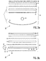
- Fig. 3(a) shows an embodiment of a flat picture display device 12 of the type using background lighting.
- the illumination system 15 comprises a light source 23 behind which a reflector 25 is arranged.
- the reflector 25 ensures that light transmitted in a direction away from the picture display panel 17 as yet reaches the picture display panel 17.
- the combination of the polarizing element 3, the depolarizing element 11 and the reflector 25 may be considered as the optical system. If the polarizing element 3 is implemented in such a way that the diffused direction of polarization is not reflected but is deflected in the forward direction, the optical system may be extended with a flat element 5, as is the case in the embodiment shown in Fig. 2.
- the flat element 5 Since the presence of the flat element 5 depends on the implementation of the polarizing element, the flat element is shown in broken lines.
- the functions of the reflector and of the depolarizing element may be combined in one and the same element which should then be arranged at the side of the radiation source 23 facing away from the polarizing element 3.
- One direction of polarization of the unpolarized light originating from the radiation source 23 is passed undeflected by the polarizing element 3 and subsequently modulated by the picture display panel 17.
- the other direction of polarization is, for example back-reflected towards the radiation source 23, depolarized by the depolarizing element 11 and reflected back to the polarizing element 3 again by the reflector 25. Approximately half thereof will have the direction of polarization suitable to be passed and will contribute to the formation of the picture.
- the process is repeated for the other half. If the polarizing element 3 is combined with a flat element 5, the back-reflection will be ensured by the flat element instead of by the polarizing element 3 itself and will be determined by the critical angle ⁇ c . In both cases, the greater part of the light supplied by the radiation source 23 will be converted into light having the same direction of polarization and will consequently contribute to the formation of the picture.
- Fig. 3(b) shows an embodiment of a flat picture display device 30 of the type using peripheral lighting.
- the picture display device 30 comprises an illumination system 27, a picture display panel 17 and an analyzer 19.
- the illumination system 27 comprises an optical guide 29 in optically transparent material, in which light coming from a light source 33 can be coupled into at least one end face 31, which light source is arranged opposite this end face. Instead of coupling light into one end face, it is possible to couple light into more end faces so that a greater brightness of the picture display device is achieved.
- a reflector 35 is arranged under the optical guide 29.
- the radiation source 33 is also surrounded by a reflector 37 so as to absorb the light transmitted by the light source 33 outside the optical guide 29 and send it as yet towards the optical guide 29.
- the surface 39 of the optical guide 29 facing away from the picture display panel 17 is provided with a dot pattern 41 of (diffusely) reflecting material.
- the density and size of the dots increases as the distance to the light source 33 in the optical guide 29 increases.
- Such a plate is known per se, for example from United States Patent US-A 4,985,809. Light which leaves the optical guide in the direction of the reflector 35 will be sent as yet towards the picture display panel by the reflector.
- a reflecting layer 43 may be provided on the end faces of the optical guide, opposite which there is no light source, so as to prevent light from exiting from the optical guide at these end faces so that it cannot contribute to the formation of the picture.
- the optical system is constituted by the depolarizing element 11, the polarizing element 3, the reflector 35 and, dependent on the implementation of the polarizing element, the flat element 5.
- the operating principle of the picture display device is analogous to that of the picture display device shown in Fig. 3(a).
- the optical system according to the invention may be used to great advantage in an image projection device with a rear-projection screen.
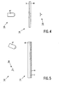
- Fig. 4 shows an embodiment of such an image projection device 45.
- the device 45 comprises a projector 47 and an image projection screen 49.
- the image projection screen 49 comprises an optically transparent plate 48 which is provided with the required lens structures for horizontal and/or vertical spread of light into the audience space.
- the projector is an LCD projector, in other words, if the picture display system of the projector comprises a liquid crystalline picture display panel, the projector supplies polarized light, hereinafter referred to as signal light.
- signal light polarized light
- ambient light is also incident on the image projection screen, which light will be diffused in the audience space 50.
- the ambience of the screen should be darkened to a great extent.
- a polarizing element 3 in which the polarizing element diffuses the signal light towards the audience, it is even not necessary to darken the ambience.
- a polarizing element 3 implemented similarly as that shown in Fig. 2 will pass substantially 50% of the ambient light so that approximately 50% less light is diffused towards the audience, as compared with an isotropic diffusing element.
- Fig. 5 shows an embodiment of an image projection device using a front-projection screen.
- the screen comprises a plate 48 as a support for the required lens structures.
- the projector 47 is an LCD projector and consequently supplies polarized light
- the signal light will be-reflected by the screen 51 if the polarizing element 3 is implemented in the way as that in Fig. 1 and if the direction of polarization which is reflected corresponds to that of the signal light.
- the polarizing element 3 By providing an absorbing element 14 behind the polarizing element 3, viewed from the audience space 50, the ambient light passed by the polarizing element 3 is absorbed. In this way, a relatively high image contrast can be achieved.
- a polarizing element of the type shown in Fig. 1 may also be used in a flat picture display device operating with ambient light.
- a flat picture display device operating with ambient light.
- Such a device is shown in Fig. 6 and comprises an analyzer 61, a picture display panel 63, a polarizing element 3 and an absorbing element 14.
- Approximately half of the ambient light incident on the device 60 will be obstructed by an analyzer 61.
- the other half is incident on the picture display panel 63 and will be modulated in conformity with the picture information to be displayed.
- the picture display panel will pass this direction of polarization undisturbed.
- the light then reaches the polarizing element which is to reflect this direction of polarization.
- the panel is in the bright state at the location of such pixels.
- the direction of polarization of the incident light will be modulated in conformity with the picture information to be displayed. Consequently, the direction of polarization will change so that this light is no longer reflected by the polarizing element 3 but is passed and consequently reaches the absorbing element 14 where it will be absorbed. Dark picture portions will be formed at the location of these pixels.
- a polarizing color filter can be realized in this way.
- the polarizing element 3 can be made from materials from which the polarizing element 3 can be made. A distinction will be made between systems with an isotropic continuous phase and an anisotropic dispersed phase, on the one hand, and systems with an anisotropic matrix in which an isotropic phase is dispersed, on the other hand.
- Polymer materials are chosen for the continuous phases.
- the dispersed phase may be both a polymer and an inorganic glass.
- the continuous phase may consist of, for example an amorphous polymer such as, for example PMMA (polymethyl methacrylate), PS (polystyrene), PC (polycarbonate), COC (cyclic olephine copolymers), PES (polyether sulphone) but also crosslinked acrylates, epoxides, urethane and silicone rubbers.
- an amorphous polymer such as, for example PMMA (polymethyl methacrylate), PS (polystyrene), PC (polycarbonate), COC (cyclic olephine copolymers), PES (polyether sulphone) but also crosslinked acrylates, epoxides, urethane and silicone rubbers.
- the dispersed phase use is preferably made of a liquid crystalline material.
- the alignment of the orientation along the macroscopic preferred direction can be realized by means of an electric or a magnetic field, but also by mechanical deformation of the droplets to, for example ellipsoids so that there is no alignment due to interface tensions.
- the orientation thus achieved can subsequently be frozen in situ by crosslinking the reactive LC molecules.
- the desired distribution of the dispersed phase can be achieved by admixing in the polymer matrix or admixing in the monomer matrix. If a monomer matrix is used, the phase separation may be induced by polymerization of the matrix (PDLC: polymer dispersed liquid crystal) or by polymerization of the reactive LC molecules.
- PDLC polymer dispersed liquid crystal
- the dispersed phase consists of fibers of, for example PET (polyethylene terephthalate), PEN (polyethylene naphthalate) or Nylon.
- the fibers are divided into relatively short pieces and subsequently admixed.
- the microscopic alignment is realized by stretching the composite so that, due to their anisotropic direction, the fibers will be oriented in the direction of stretching.
- the fibers may also be incorporated quasi-continuously with their full length in a matrix comprising a thermoplastic or a thermosetting agent. In this case, stretching will not be necessary because the fibers maintain their imposed orientation during impregnation.
- the refractive indices of the dispersed phase and of the continuous phase should be substantially equal to each other.
- a system with an anisotropic continuous phase and an isotropic dispersed phase can be realized by means of, for example a mixture of two thermoplastic polymers, for example PET and COC.
- the mixing ratio determines the concentration of diffusing particles.
- PET will constitute the continuous phase.
- the mixing time is, for example 1 to 2 minutes and the mixing temperature is 250-270 °C. In this way, a relatively fine dispersion of COC can be achieved.
- the mixture can be pressed or extruded to form a foil.
- the foil is subsequently uniaxially stretched with an effective tension difference in the foil of at least 10 MPa at a temperature which is preferably lower than 90 °C.
- the foil is then further cooled down to room temperature while maintaining a constant tension.
- the COC will also be subjected to a load before stretching itself occurs. It is therefore desirable to choose a COC having a low glass-transition temperature which is lower than that of PET. In that case, the dispersed COC phase can easily deform together with a matrix. The tension in the COC phase then remains low so that there will be no cavitation at the interface.
- the refractive index of COC is relatively insensitive to tensions so that the refractive index will differ to a slight extent from 1.53 and is thus substantially equal to n o of PET. Cavitation on the interface is not desirable because there will be dispersion for both polarization components in that case, resulting in a decrease of the contrast.
- Such particles may be, for example core-shell rubber particles or polymer particles which are obtained, for example, by means of emulsion polymerization.
- the particle size can be adjusted by setting the conditions of polymerization. Consequently, the particle size is independent of the mixing technique and constant throughout the operating steps. Soft particles have the advantage that cavitation will not readily occur.
- polymer particles inorganic particles such as, for example, glass granules or fibers may be mixed.
- refractive index so that, in principle, the refractive index of the particles can be rendered equal to both n o and n e .
- the particle size may be determined in advance in conformity with the desired diffusion pattern.
- the optical anisotropy of the matrix is obtained by uniaxially stretching the composite, as described hereinbefore.
Landscapes
- Physics & Mathematics (AREA)
- General Physics & Mathematics (AREA)
- Optics & Photonics (AREA)
- Polarising Elements (AREA)
Claims (11)
- Optisches System mit einem Polarisationselement (3) und Mitteln (4, 5), um zumindest einen Teil der im Polarisationselement gestreuten Polarisationskomponente zurückzuwerfen, dadurch gekennzeichnet, dass das Polarisationselement in Form einer Schicht ein isotropes Material mit einem Brechungskoeffizienten ni und ein anisotropes Material mit den Brechungskoeffizienten na,e und na,o umfasst, wobei ni im Wesentlichen gleich na,e oder na,o ist.
- Optisches System nach Anspruch 1, wobei das anisotrope Material durch Partikel gebildet wird, für die gilt, dass:
- Optisches System nach Anspruch 1, wobei die Mittel für die Retroreflexion durch ein flaches Element gebildet werden, das auf einer dem Polarisationselement zugewandten Seite mit einer Reliefstruktur versehen ist, wobei das genannte Element eine Reflexionswirkung bei Lichtstrahlen mit einem Einfallswinkel hat, der größer als der kritische Winkel c ist.
- Optisches System nach einem der vorhergehenden Ansprüche, wobei gilt:
- Optisches System nach Anspruch 1, 2, 3, oder 4, wobei das optische System weiterhin Mittel umfasst, um die gestreute Polarisationskomponente zumindest teilweise in eine komplementär polarisierte Komponente umzuwandeln.
- Optisches System nach Anspruch 5, wobei die Mittel für die Polarisationsumwandlung aus einem Depolarisator und einem Reflektor bestehen.
- Flachbildanzeigevorrichtung mit einem Bildanzeigefeld, um die Polarisationsrichtung des einfallenden Umgebungslichts mit Bildinformationen zu modulieren, und optisches System nach Anspruch 1, 2 oder 4 mit einem Absorptionselement, das auf der dem Bildanzeigefeld abgewandten Seite des Polarisationselements angeordnet ist.
- Flachbildanzeigevorrichtung mit einem Beleuchtungssystem zur Erzeugung eines Lichtstrahls, einem Bildanzeigefeld mit einer flüssigkristallinen Schicht, um den genannten Lichtstrahl in Übereinstimmung mit anzuzeigenden Bildinformationen zu modulieren, und einem optischen System nach einem der Ansprüche 1 bis 6.
- Flachbildanzeigevorrichtung nach Anspruch 7 und weiterhin mit einem Beleuchtungssystem zur Erzeugung eines Lichtstrahls.
- Bildprojektionsvorrichtung mit einem Bildprojektor, um einen mit einer genau definierten Polarisationsrichtung zu projizierenden Strahl zu liefern, einem Rückprojektionsbildschirm mit einem Polarisationselement, dessen Polarisationsrichtung der Polarisationsrichtung des zu projizierenden Strahls entspricht, und einem optischen System nach einem der Ansprüche 1, 2 oder 4.
- Bildprojektionsvorrichtung mit einem Bildprojektor, um einen mit einer genau definierten Polarisationsrichtung zu projizierenden Strahl zu liefern, einem Aufprojektionsbildschirm mit einem Polarisationselement, dessen Polarisationsrichtung der Polarisationsrichtung des zu projizierenden Strahls entspricht, und einem optischen System nach einem der Ansprüche 1, 2 oder 4, wobei ein Absorptionselement auf der dem Projektor abgewandten Seite des Polarisationselements angeordnet ist.
Priority Applications (1)
| Application Number | Priority Date | Filing Date | Title |
|---|---|---|---|
| EP97908467A EP0835476B1 (de) | 1996-04-26 | 1997-04-08 | Optisches system |
Applications Claiming Priority (4)
| Application Number | Priority Date | Filing Date | Title |
|---|---|---|---|
| EP96201142 | 1996-04-26 | ||
| EP96201142 | 1996-04-26 | ||
| PCT/IB1997/000370 WO1997041484A1 (en) | 1996-04-26 | 1997-04-08 | Optical system |
| EP97908467A EP0835476B1 (de) | 1996-04-26 | 1997-04-08 | Optisches system |
Publications (2)
| Publication Number | Publication Date |
|---|---|
| EP0835476A1 EP0835476A1 (de) | 1998-04-15 |
| EP0835476B1 true EP0835476B1 (de) | 2004-11-03 |
Family
ID=8223933
Family Applications (1)
| Application Number | Title | Priority Date | Filing Date |
|---|---|---|---|
| EP97908467A Expired - Lifetime EP0835476B1 (de) | 1996-04-26 | 1997-04-08 | Optisches system |
Country Status (5)
| Country | Link |
|---|---|
| US (1) | US5940211A (de) |
| EP (1) | EP0835476B1 (de) |
| JP (1) | JPH11509014A (de) |
| DE (1) | DE69731446T2 (de) |
| WO (1) | WO1997041484A1 (de) |
Families Citing this family (31)
| Publication number | Priority date | Publication date | Assignee | Title |
|---|---|---|---|---|
| US5825543A (en) * | 1996-02-29 | 1998-10-20 | Minnesota Mining And Manufacturing Company | Diffusely reflecting polarizing element including a first birefringent phase and a second phase |
| US6627300B1 (en) | 1997-10-12 | 2003-09-30 | 3M Innovative Properties Company | Optical device containing polymeric material domains having different degrees of randomness |
| US6157486A (en) * | 1998-01-13 | 2000-12-05 | 3M Innovative Properties Company | Retroreflective dichroic reflector |
| JPH11281970A (ja) * | 1998-03-30 | 1999-10-15 | Toshiba Corp | 反射型液晶表示素子 |
| TW507104B (en) * | 1998-09-16 | 2002-10-21 | Teijin Ltd | Application of light source including light guide for emanating linearly polarized light to liquid crystal display |
| JP2000226458A (ja) * | 1999-02-08 | 2000-08-15 | Nitto Denko Corp | 光学フィルム、光学部材及び光学素子 |
| JP4251700B2 (ja) * | 1999-02-08 | 2009-04-08 | 日東電工株式会社 | 光学フィルム、光学部材及び光学素子 |
| US6381068B1 (en) * | 1999-03-19 | 2002-04-30 | 3M Innovative Properties Company | Reflective projection screen and projection system |
| US6515785B1 (en) * | 1999-04-22 | 2003-02-04 | 3M Innovative Properties Company | Optical devices using reflecting polarizing materials |
| JP3383260B2 (ja) * | 1999-04-26 | 2003-03-04 | 日東電工株式会社 | ニュートラル偏光板及び液晶表示装置 |
| US6952310B1 (en) * | 1999-05-12 | 2005-10-04 | Nitto Denko Corporation | Light pipe and polarized-light source |
| US6239907B1 (en) | 1999-09-03 | 2001-05-29 | 3M Innovative Properties Company | Rear projection screen using birefringent optical film for asymmetric light scattering |
| US6654170B1 (en) | 1999-10-12 | 2003-11-25 | 3M Innovative Properties Company | Optical device having continuous and disperse phases |
| US6673275B1 (en) | 1999-10-12 | 2004-01-06 | 3M Innovative Properties Company | Method for making optical devices from homopolymers |
| JP2001228332A (ja) * | 1999-12-09 | 2001-08-24 | Sumitomo Chem Co Ltd | 偏光素子、偏光光源装置及び液晶表示装置 |
| JP4614400B2 (ja) * | 2000-01-17 | 2011-01-19 | 日東電工株式会社 | 有機el発光装置、偏光面光源装置及び液晶表示装置 |
| WO2001053745A1 (en) | 2000-01-19 | 2001-07-26 | Omlidon Technologies Llc | Polarizing device |
| EP1194794A2 (de) * | 2000-03-15 | 2002-04-10 | Koninklijke Philips Electronics N.V. | Projektionsschirm |
| US7072544B2 (en) * | 2000-05-19 | 2006-07-04 | Koninklijke Philips Electronics N.V. | Polarized light-emitting waveguide plate |
| TW522259B (en) * | 2000-07-21 | 2003-03-01 | Sumitomo Chemical Co | Anisotropic scattering film and liquid crystal display |
| JP3858581B2 (ja) | 2000-09-26 | 2006-12-13 | セイコーエプソン株式会社 | 液晶装置及び電子機器 |
| US20030090012A1 (en) * | 2001-09-27 | 2003-05-15 | Allen Richard Charles | Methods of making polarization rotators and articles containing the polarization rotators |
| US6985291B2 (en) * | 2001-10-01 | 2006-01-10 | 3M Innovative Properties Company | Non-inverting transflective assembly |
| TW200303354A (en) | 2002-02-05 | 2003-09-01 | Sumitomo Chemicalco Ltd | Anisotropic film and LCD using the same |
| US20060290843A1 (en) * | 2005-06-24 | 2006-12-28 | Epstein Kenneth A | Illumination element and system using same |
| US20060290845A1 (en) * | 2005-06-24 | 2006-12-28 | Hebrink Timothy J | Polarization sensitive illumination element and system using same |
| US7903194B2 (en) * | 2005-06-24 | 2011-03-08 | 3M Innovative Properties Company | Optical element for lateral light spreading in back-lit displays and system using same |
| US8023065B2 (en) * | 2005-06-24 | 2011-09-20 | 3M Innovative Properties Company | Optical element for lateral light spreading in edge-lit displays and system using same |
| WO2008041425A1 (fr) * | 2006-09-29 | 2008-04-10 | Konica Minolta Opto, Inc. | Film optique, procédé de fabrication de celui-ci, film de protection pour plaque de polarisation, plaque de polarisation utilisant le film de protection, et dispositif d'affichage à cristaux liquides |
| DE102007006825A1 (de) | 2007-02-07 | 2008-08-14 | Evonik Röhm Gmbh | Kunststoffformkörper mir anisotroper Lichtstreuung |
| US9310619B2 (en) * | 2012-02-15 | 2016-04-12 | Sharp Kabushiki Kaisha | Optical film |
Family Cites Families (5)
| Publication number | Priority date | Publication date | Assignee | Title |
|---|---|---|---|---|
| JPH0670882B2 (ja) * | 1988-08-23 | 1994-09-07 | 株式会社明拓システム | 単板使用エッジライトパネル |
| US5157526A (en) * | 1990-07-06 | 1992-10-20 | Hitachi, Ltd. | Unabsorbing type polarizer, method for manufacturing the same, polarized light source using the same, and apparatus for liquid crystal display using the same |
| US5422756A (en) * | 1992-05-18 | 1995-06-06 | Minnesota Mining And Manufacturing Company | Backlighting system using a retroreflecting polarizer |
| EP0573905A1 (de) * | 1992-06-08 | 1993-12-15 | Minnesota Mining And Manufacturing Company | Rückstrahlender Polarisator für Anzeigesysteme |
| BE1007592A3 (nl) * | 1993-10-06 | 1995-08-16 | Philips Electronics Nv | Reflecterend beeldprojectiescherm en beeldprojectiesysteem bevattende een dergelijk beeldprojectiescherm. |
-
1997
- 1997-04-08 DE DE69731446T patent/DE69731446T2/de not_active Expired - Fee Related
- 1997-04-08 EP EP97908467A patent/EP0835476B1/de not_active Expired - Lifetime
- 1997-04-08 JP JP9538694A patent/JPH11509014A/ja active Pending
- 1997-04-08 WO PCT/IB1997/000370 patent/WO1997041484A1/en active IP Right Grant
- 1997-04-16 US US08/834,408 patent/US5940211A/en not_active Expired - Fee Related
Also Published As
| Publication number | Publication date |
|---|---|
| EP0835476A1 (de) | 1998-04-15 |
| WO1997041484A1 (en) | 1997-11-06 |
| JPH11509014A (ja) | 1999-08-03 |
| DE69731446D1 (de) | 2004-12-09 |
| US5940211A (en) | 1999-08-17 |
| DE69731446T2 (de) | 2005-10-13 |
Similar Documents
| Publication | Publication Date | Title |
|---|---|---|
| EP0835476B1 (de) | Optisches system | |
| US5099343A (en) | Edge-illuminated liquid crystal display devices | |
| EP0787316B1 (de) | Beleuchtungssystem für eine flachtafel-bildanzeigevorrichtung | |
| US5899551A (en) | Display device having a diffusing display panel and a reflecting polarizer | |
| US5751388A (en) | High efficiency polarized display | |
| US7903194B2 (en) | Optical element for lateral light spreading in back-lit displays and system using same | |
| KR101087627B1 (ko) | 내장된 화면 표시 장치를 구비한 거울 | |
| US7072544B2 (en) | Polarized light-emitting waveguide plate | |
| US6504589B1 (en) | Backlight device and liquid crystal display device | |
| KR100428523B1 (ko) | 플랫-패널화상디스플레이디바이스 | |
| US7322731B2 (en) | Color mixing illumination light unit and system using same | |
| US8023065B2 (en) | Optical element for lateral light spreading in edge-lit displays and system using same | |
| US20060290843A1 (en) | Illumination element and system using same | |
| KR20040019257A (ko) | 고휘도 반투과형 액정 디스플레이 및 가변형 거울의 사용방법 | |
| EP0868681A1 (de) | Beleuchtungssystem für flachbildanzeigevorrichtung | |
| WO2007002101A1 (en) | Polarization sensitive illumination element and system using same | |
| JPH11160687A (ja) | 表示装置及び光拡散層の製造方法 | |
| JP3474527B2 (ja) | 反射型液晶表示装置 | |
| IL126255A (en) | High efficiency polarized display |
Legal Events
| Date | Code | Title | Description |
|---|---|---|---|
| PUAI | Public reference made under article 153(3) epc to a published international application that has entered the european phase |
Free format text: ORIGINAL CODE: 0009012 |
|
| AK | Designated contracting states |
Kind code of ref document: A1 Designated state(s): DE FR GB |
|
| RAP3 | Party data changed (applicant data changed or rights of an application transferred) |
Owner name: KONINKLIJKE PHILIPS ELECTRONICS N.V. |
|
| 17P | Request for examination filed |
Effective date: 19980506 |
|
| GRAP | Despatch of communication of intention to grant a patent |
Free format text: ORIGINAL CODE: EPIDOSNIGR1 |
|
| GRAS | Grant fee paid |
Free format text: ORIGINAL CODE: EPIDOSNIGR3 |
|
| GRAA | (expected) grant |
Free format text: ORIGINAL CODE: 0009210 |
|
| AK | Designated contracting states |
Kind code of ref document: B1 Designated state(s): DE FR GB |
|
| REG | Reference to a national code |
Ref country code: GB Ref legal event code: FG4D |
|
| REG | Reference to a national code |
Ref country code: GB Ref legal event code: 746 Effective date: 20041108 |
|
| REF | Corresponds to: |
Ref document number: 69731446 Country of ref document: DE Date of ref document: 20041209 Kind code of ref document: P |
|
| PLBE | No opposition filed within time limit |
Free format text: ORIGINAL CODE: 0009261 |
|
| STAA | Information on the status of an ep patent application or granted ep patent |
Free format text: STATUS: NO OPPOSITION FILED WITHIN TIME LIMIT |
|
| ET | Fr: translation filed | ||
| 26N | No opposition filed |
Effective date: 20050804 |
|
| REG | Reference to a national code |
Ref country code: FR Ref legal event code: D6 |
|
| PGFP | Annual fee paid to national office [announced via postgrant information from national office to epo] |
Ref country code: GB Payment date: 20060425 Year of fee payment: 10 |
|
| PGFP | Annual fee paid to national office [announced via postgrant information from national office to epo] |
Ref country code: FR Payment date: 20060426 Year of fee payment: 10 |
|
| PGFP | Annual fee paid to national office [announced via postgrant information from national office to epo] |
Ref country code: DE Payment date: 20060619 Year of fee payment: 10 |
|
| GBPC | Gb: european patent ceased through non-payment of renewal fee |
Effective date: 20070408 |
|
| PG25 | Lapsed in a contracting state [announced via postgrant information from national office to epo] |
Ref country code: DE Free format text: LAPSE BECAUSE OF NON-PAYMENT OF DUE FEES Effective date: 20071101 |
|
| PG25 | Lapsed in a contracting state [announced via postgrant information from national office to epo] |
Ref country code: GB Free format text: LAPSE BECAUSE OF NON-PAYMENT OF DUE FEES Effective date: 20070408 |
|
| PG25 | Lapsed in a contracting state [announced via postgrant information from national office to epo] |
Ref country code: FR Free format text: LAPSE BECAUSE OF NON-PAYMENT OF DUE FEES Effective date: 20070430 |