EP0834665A2 - Full perimeter fiber wound bearing construction - Google Patents
Full perimeter fiber wound bearing construction Download PDFInfo
- Publication number
- EP0834665A2 EP0834665A2 EP97306983A EP97306983A EP0834665A2 EP 0834665 A2 EP0834665 A2 EP 0834665A2 EP 97306983 A EP97306983 A EP 97306983A EP 97306983 A EP97306983 A EP 97306983A EP 0834665 A2 EP0834665 A2 EP 0834665A2
- Authority
- EP
- European Patent Office
- Prior art keywords
- bearing
- accordance
- bore
- assembly
- sleeve
- Prior art date
- Legal status (The legal status is an assumption and is not a legal conclusion. Google has not performed a legal analysis and makes no representation as to the accuracy of the status listed.)
- Granted
Links
Images
Classifications
-
- F—MECHANICAL ENGINEERING; LIGHTING; HEATING; WEAPONS; BLASTING
- F16—ENGINEERING ELEMENTS AND UNITS; GENERAL MEASURES FOR PRODUCING AND MAINTAINING EFFECTIVE FUNCTIONING OF MACHINES OR INSTALLATIONS; THERMAL INSULATION IN GENERAL
- F16C—SHAFTS; FLEXIBLE SHAFTS; ELEMENTS OR CRANKSHAFT MECHANISMS; ROTARY BODIES OTHER THAN GEARING ELEMENTS; BEARINGS
- F16C23/00—Bearings for exclusively rotary movement adjustable for aligning or positioning
- F16C23/02—Sliding-contact bearings
- F16C23/04—Sliding-contact bearings self-adjusting
- F16C23/043—Sliding-contact bearings self-adjusting with spherical surfaces, e.g. spherical plain bearings
- F16C23/045—Sliding-contact bearings self-adjusting with spherical surfaces, e.g. spherical plain bearings for radial load mainly, e.g. radial spherical plain bearings
-
- F—MECHANICAL ENGINEERING; LIGHTING; HEATING; WEAPONS; BLASTING
- F16—ENGINEERING ELEMENTS AND UNITS; GENERAL MEASURES FOR PRODUCING AND MAINTAINING EFFECTIVE FUNCTIONING OF MACHINES OR INSTALLATIONS; THERMAL INSULATION IN GENERAL
- F16C—SHAFTS; FLEXIBLE SHAFTS; ELEMENTS OR CRANKSHAFT MECHANISMS; ROTARY BODIES OTHER THAN GEARING ELEMENTS; BEARINGS
- F16C33/00—Parts of bearings; Special methods for making bearings or parts thereof
- F16C33/02—Parts of sliding-contact bearings
- F16C33/04—Brasses; Bushes; Linings
- F16C33/20—Sliding surface consisting mainly of plastics
-
- F—MECHANICAL ENGINEERING; LIGHTING; HEATING; WEAPONS; BLASTING
- F16—ENGINEERING ELEMENTS AND UNITS; GENERAL MEASURES FOR PRODUCING AND MAINTAINING EFFECTIVE FUNCTIONING OF MACHINES OR INSTALLATIONS; THERMAL INSULATION IN GENERAL
- F16G—BELTS, CABLES, OR ROPES, PREDOMINANTLY USED FOR DRIVING PURPOSES; CHAINS; FITTINGS PREDOMINANTLY USED THEREFOR
- F16G13/00—Chains
- F16G13/02—Driving-chains
- F16G13/06—Driving-chains with links connected by parallel driving-pins with or without rollers so called open links
Definitions
- This invention relates generally to composite journal bearings, and, more particularly, to an improved composite ball and socket journal bearing assembly.
- Prior designs for journal bearings include location of a self-lubricating bearing surface on the inside diameter of a stationary member which houses the rotating shaft.
- the rotating shaft engages or contacts up to about 240 degrees of the self-lubricating bearing surface, causing the load on the bearing surface to be concentrated, thereby resulting in shortening of the useful life of the bearing.
- the invention provides a bearing assembly comprising an outer non-rotational member having a bore with an inwardly facing bearing surface, and an inner rotating member including an inner portion, and an outwardly facing self-lubricating bearing surface received in the inwardly facing bearing surface of the outer stationary member.
- the wear life of the bearing assembly is improved because the entire circumference of the self-lubricating bearing surface is load bearing as the bearing surface rotates.
- the invention also provides a bearing assembly comprising an outer stationary bearing member having a bore with an inwardly facing cylindrical bearing surface, and an inner rotating assembly including a bearing sleeve having an internal bore, and an outwardly facing self-lubricating cylindrical bearing surface received in the inwardly facing bearing surface of the outer stationary bearing member, and a shaft received in the internal bore of the bearing sleeve and fixed to the bearing sleeve for common rotary movement with the bearing sleeve.
- the invention also provides a bearing assembly comprising an outer stationary assembly including a housing having an axial bore with an inwardly facing spherical surface, and an outer bearing member including an outwardly facing spherical surface received in the inwardly facing spherical surface of the housing block and a bore including an inwardly facing cylindrical bearing surface, and an inner rotating assembly including a rotating shaft, and a bearing sleeve fixed to the shaft for common rotation and including an axial bore receiving the shaft, and an outwardly facing composite fabric self-lubricating bearing having an outwardly facing cylindrical bearing surface received in the inwardly facing bearing surface of the outer bearing member.
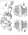
- FIG. 1 is an exploded perspective view of a bearing assembly which incorporates various features of the invention.
- FIG. 2 is a sectional view of the of the bearing assembly shown in Figure 1.
- FIG. 3 is a sectional view of another embodiment of a bearing assembly incorporating various of the features of the invention.
- FIG. 1 Shown in FIG. 1 is a bearing assembly 8 including a ball and socket non-rotational or stationary bearing assembly 10 of the type including a non-rotational member or flange block or housing 12, and a bearing subassembly 14 which can be inserted and retained or housed within the housing 12.
- a bearing assembly 8 including a ball and socket non-rotational or stationary bearing assembly 10 of the type including a non-rotational member or flange block or housing 12, and a bearing subassembly 14 which can be inserted and retained or housed within the housing 12.
- the housing 12 comprises a body 16 having an axis 18 and axially spaced sides 22 and 23. Extending between the axially spaced sides 22 is an axially extending bore 24 having an inwardly facing concave or spherical mounting surface or socket 26. The diameter of the mounting socket 26 diminishes in either axial direction from a central maximum diameter to opposed circumferential regions of minimum diameter 30 at the housing sides 22.
- the housing 12 also includes insertion slot means extending axially from one of the sides 22 and 23 in the housing 12 and terminating adjacent the central maximum diameter.
- the insertion slot means preferably comprises two insertion slots 34 which are diametrically spaced apart a distance at least equal to the diameter of the region of maximum diameter in the concave mounting socket 26.
- the bearing subassembly 14 generally includes a one piece, integrally formed annular intermediate socket member 40 having a socket axis and axially spaced ends 44 and 46.
- An axial socket bore extends between the axial ends 44 and 46 and is defined by an inwardly facing, concave inner raceway or bore 50.
- the concave inner raceway 50 includes a bearing surface, such as a liner of self-lubricating low-friction material, which is integrally bonded to the concave inner raceway 50.
- the self-lubricating material can comprise a fabric woven from fibers of self-lubricating material, and if the intermediate socket member 40 is of fiberglass, the material may be bonded to the concave inner raceway 50 by the method disclosed in the U. S. Pat. Nos. 3,700,295 and 3,974,009 referenced above.
- a preferred intermediate socket member 40 comprises a hardened resin body reinforced by glass filaments or some other reinforcing filaments which includes the self-lubricating low-friction material lining the concave inner raceway 50.
- the intermediate socket member 40 also includes a convex, generally spherical outer surface 54 which is ground or otherwise machined on the outer diameter of the one piece intermediate socket member 40.
- the convex outer surface 54 has a dimension complementary to the inwardly facing concave mounting socket 26 of the housing 12.
- the one piece intermediate socket member 40 also has an installation axis extending transversely to the housing axis 18 and the socket axis.
- the width across the axially spaced intermediate socket ends 44 and 46 is slightly less than the width of the insertion slots 34, which width permits the one piece intermediate socket member 40 of the subassembly 14 to be inserted into the insertion slots 34 and then turned to seat the convex outer surface 54 of the one piece intermediate socket meter 40 in the housing concave mounting socket 26, thereby installing the bearing subassembly 14 within the housing 12.
- the bearing subassembly 14 can similarly be removed from the housing 12 by simply turning the intermediate socket member 40 ninety degrees (90°) to align the intermediate socket member 40 with the insertion slots 34 and then sliding the intermediate socket member 40 away from the housing 12 along the housing axis 18.
- a layer of self-lubricating material may be bonded to the convex outer surface 54 of the one piece intermediate socket member 40.
- the bearing subassembly 14 also includes a spherical bearing member or ball 60 which is mounted within the one piece annular intermediate socket member 40 and which can be generally stationary with respect to, or free to move and to rotate within, the intermediate socket member 40.
- the outer bearing member or ball member 60 includes flat circular end faces 64 and 65 and is provided with a central bore defined by an inwardly facing bearing surface 62. While other constructions can be employed, in the disclosed construction, the inwardly facing bearing surface 62 is cylindrical.
- the outer bearing member or ball member also includes an external spherical bearing surface 68 which is in contact with the concave inner raceway 50 and which can accommodate misalignment or rotation within the intermediate socket member 40.
- the outer bearing member or ball member 60 can be fabricated of metal, and the external spherical bearing surface 68 of the outer bearing member can be lined with self-lubricating material integrally bonded to the metal by the method described above for applying self-lubricating material to the convex outer surface 54.
- the outer bearing or ball member 60 can be fabricated from a fiberglass material.
- the intermediate socket member 40 After the intermediate socket member 40 has been placed into the insertion slots 34 and turned to the housing bore 24 ninety degrees (90°), the intermediate socket member 40 is sandwiched between the spherical outer bearing member or ball member 60 and the housing 12 and the bearing subassembly 14 and is ready to support a load.
- an inner rotating member or shaft or shaft assembly which can be a shaft having thereon an external bearing surface of self-lubricating material (not shown), or which can be an inner rotating assembly including a shaft and an outer bearing sleeve having common rotation with the shaft and an external bearing surface of self-lubricating material.
- the bearing assembly 10 preferably includes an inner rotating assembly 71 which is located in the inwardly facing bearing surface or bore 62 of the outer bearing member or ball member 60 and includes the before mentioned shaft or inner part 73 and the before mentioned outer bearing part or bearing sleeve 75 which surrounds the shaft 73 for common rotation therewith and which includes the before mentioned outer or external bearing surface 77 of self-lubricating material.
- the inner rotatable shaft 73 can be of any suitable construction and is illustrated as having at least a portion with a hexagonal cross-section.
- the outer bearing part or bearing sleeve 75 includes a main body 81 having a bore 83 receiving the shaft 73 so as to have common rotation with the shaft 73.
- the outer bearing part or bearing sleeve 75 includes a bearing portion having the outwardly facing, self-lubricating bearing surface 77 received in and engaging the inwardly facing bearing surface 62 of the outer bearing member or ball member 60. While other constructions can be employed, in the disclosed construction, the outwardly facing bearing surface 77 is cylindrical.
- the bearing sleeve 75 can be fabricated in one piece from a woven fabric and resinous composite material which is self-lubricating.
- the main body 81 can be fabricated of metal having an outer surface provided with a layer of self-lubricating material which is bonded to the outer surface of the main body 81 and provides the bearing surface 77.
- the self-lubricating material is a composite material including woven self-lubricating fabric and resin.
- the bore 83 of the main body 81 has a non-circular shape or configuration
- the shaft 73 has a complimentary outer surface portion 91 engaged in the non-circular bore 83 to prevent rotary movement therebetween.
- the non circular shape is hexagonal.
- the non-circular shape can be square. Other non-circular shapes can also be used.
- the bore 83 of the bearing sleeve 75 can be cylindrical and the shaft 73 can be pressed fitted into the bore 83.
- the inwardly facing bearing surface 62 of the outer bearing member or ball member 60 is preferably metallic.
- the inwardly facing bearing surface 62 of the outer bearing member or ball member 60 can be of self-lubricating material, such as the before mentioned composite material including woven fabric and resin.
- the disclosed construction provides an improved bearing assembly 8 with increased useful life by placing the self-lubricating bearing surface 77 on a rotating shaft or sleeve member.
- the full circumferential extent of the self-lubricating bearing surface 77 is exposed to the load as the bearing rotates.
- the preferred construction comprises the bearing sleeve 75 having the external, outwardly facing cylindrical, self-lubricating bearing surface 77, and the inner bore 83 which can be cylindrical, hexagonal, or square, etc., and which receives, and is fixed for common rotation to, the rotating shaft 73.
- the bearing subassembly 14 can be fabricated as a single composite member including the outwardly facing convex outer surface 54 and the inwardly facing bearing surface 62.
- the inwardly facing bearing surface 62 of the outer bearing member 60 (engaged by the outwardly facing bearing surface 77 of the sleeve member 75) can be (as shown in Figure 2) a metallic bearing surface 91 or, if light loads are involved, can be (as shown in Figure 3) a self-lubricating bearing surface or layer 93.
- the metallic bearing surface 91 can be press fitted into a suitable housing which, in the disclosed construction, is the ball member 60.
- the inwardly facing metallic bearing surface 91 acts to transfer heat, thereby enabling increased operating velocity by providing a better heat sink.
- wear occurs about the entire arcuate length of the self-lubricating bearing surface 77.
- the outwardly facing, cylindrical self-lubricating bearing surface 77 of the sleeve member 75 can rotate against the inwardly facing self-lubricating bearing surface 93 of the outer bearing or ball member 60 to provide superior corrosion resistance.
- the inner bearing member or sleeve member 75 (with an outer layer of self lubricating material providing the continuous external bearing surface 77) can run on the outer bearing member or ball member 60 (having an inner bore lined with self-fabricating material to provide the self-lubricating bearing surface or layer 93) and still provide adequate bearing life.
Landscapes
- Engineering & Computer Science (AREA)
- General Engineering & Computer Science (AREA)
- Mechanical Engineering (AREA)
- Sliding-Contact Bearings (AREA)
- Support Of The Bearing (AREA)
- Laminated Bodies (AREA)
Abstract
Description
Claims (22)
- A bearing assembly comprising an outer non-rotational member having a bore with an inwardly facing bearing surface, and an inner rotating member including an inner portion, and an outwardly facing self-lubricating bearing surface received in said inwardly facing bearing surface of said outer stationary member.
- A bearing assembly in accordance with Claim 1 wherein said self-lubricating bearing surface is fabricated of woven fabric.
- A bearing assembly in accordance with Claim 1 wherein said bearing surfaces are cylindrical.
- A bearing assembly comprising an outer stationary bearing member having a bore with an inwardly facing cylindrical bearing surface, and an inner rotating assembly including a bearing sleeve having an internal bore, and an outwardly facing self-lubricating cylindrical bearing surface received in said inwardly facing bearing surface of said outer stationary bearing member, and a shaft received in said internal bore of said bearing sleeve and fixed to said bearing sleeve for common rotary movement with said bearing sleeve.
- A bearing assembly in accordance with Claim 4 wherein said bore of said bearing sleeve has an hexagonal cross-section.
- A bearing assembly in accordance with Claim 4 wherein said bore of said bearing sleeve has a cylindrical cross-section.
- A bearing assembly in accordance with Claim 4 wherein said bore of said bearing sleeve has a non-cylindrical cross-section.
- A bearing assembly in accordance with Claim 4 wherein said bore of said bearing sleeve has a square cross-section.
- A bearing assembly in accordance with Claim 4 wherein said inwardly facing bearing surface is metallic.
- A bearing assembly in accordance with Claim 4 wherein said inwardly facing bearing surface is fabricated of self-lubricating non-metallic material.
- A bearing assembly in accordance with Claim 4 wherein said bearing sleeve includes an outer portion, and an outwardly facing composite fabric bearing bonded to said outer portion and including said outwardly facing bearing surface received in said inwardly facing bearing surface of said outer bearing member.
- A bearing assembly in accordance with Claim 4 wherein said composite fabric bearing includes a woven fabric.
- A bearing assembly in accordance with Claim 12 wherein said outwardly facing bearing surface extends endlessly.
- A bearing assembly comprising an outer stationary assembly including a housing having an axial bore with an inwardly facing spherical surface, an outer bearing member including an outwardly facing spherical surface received in said inwardly facing spherical surface of said housing and a bore including an inwardly facing cylindrical bearing surface, and an inner rotating assembly including a rotating shaft, and a bearing sleeve fixed to said shaft for common rotation and including an axial bore receiving said shaft, and an outwardly facing composite fabric self-lubricating bearing having an outwardly facing cylindrical bearing surface received in said inwardly facing bearing surface of said outer bearing member.
- A bearing assembly in accordance with Claim 14 wherein said bore of said sleeve has an hexagonal cross-section.
- A bearing assembly in accordance with Claim 14 wherein said bore of said sleeve has a non-cylindrical cross-section.
- A bearing assembly in accordance with Claim 14 wherein said bore of said sleeve has a cylindrical cross-section.
- A bearing assembly in accordance with Claim 14 wherein said bore of said sleeve has a square cross-section.
- A bearing assembly in accordance with Claim 14 wherein said inwardly facing bearing surface of said outer bearing member is metallic.
- A bearing assembly in accordance with Claim 14 wherein said inwardly facing bearing surface of said outer bearing member is fabricated of self-lubricating non-metallic material.
- A bearing assembly in accordance with Claim 14 wherein said outer composite fabric bearing part includes a woven fabric.
- A bearing assembly in accordance with Claim 14 wherein said outwardly facing bearing surface extends endlessly.
Applications Claiming Priority (2)
| Application Number | Priority Date | Filing Date | Title |
|---|---|---|---|
| US725358 | 1996-10-03 | ||
| US08/725,358 US5762424A (en) | 1996-10-03 | 1996-10-03 | Full perimeter fiber wound bearing construction |
Publications (3)
| Publication Number | Publication Date |
|---|---|
| EP0834665A2 true EP0834665A2 (en) | 1998-04-08 |
| EP0834665A3 EP0834665A3 (en) | 1998-11-18 |
| EP0834665B1 EP0834665B1 (en) | 2003-05-14 |
Family
ID=24914218
Family Applications (1)
| Application Number | Title | Priority Date | Filing Date |
|---|---|---|---|
| EP97306983A Expired - Lifetime EP0834665B1 (en) | 1996-10-03 | 1997-09-09 | Full perimeter fiber wound bearing construction |
Country Status (6)
| Country | Link |
|---|---|
| US (1) | US5762424A (en) |
| EP (1) | EP0834665B1 (en) |
| JP (1) | JPH10131961A (en) |
| AT (1) | ATE240465T1 (en) |
| CA (1) | CA2214939C (en) |
| DE (1) | DE69721926T2 (en) |
Cited By (2)
| Publication number | Priority date | Publication date | Assignee | Title |
|---|---|---|---|---|
| EP0969217A2 (en) * | 1998-06-05 | 2000-01-05 | Rexnord Corporation | Composite spherical bearing and method of producing same |
| FR2811040A1 (en) * | 2000-06-30 | 2002-01-04 | Henry Graf | Articulated joint for scaffolding has plate and shaft with ball and socket joint having defined degrees of freedom |
Families Citing this family (31)
| Publication number | Priority date | Publication date | Assignee | Title |
|---|---|---|---|---|
| CZ410497A3 (en) * | 1996-12-20 | 1998-07-15 | W. Schlafhorst Ag Und Co. | Axial mounting of open-end spinning machine |
| US6089960A (en) * | 1998-06-03 | 2000-07-18 | One Source Manufacturing | Semiconductor wafer polishing mechanism |
| US6069432A (en) * | 1998-10-29 | 2000-05-30 | Shop Vac Corporation | Rotor structure |
| BE1014043A3 (en) * | 2001-03-07 | 2003-03-04 | Atlas Copco Airpower Nv | Water injected screw compressor element. |
| DE10154193A1 (en) * | 2001-11-07 | 2003-05-15 | Zf Lemfoerder Metallwaren Ag | sleeve joint |
| DE10220611A1 (en) * | 2002-02-15 | 2003-08-28 | Brueninghaus Hydromatik Gmbh | rotary bearings |
| WO2003069174A1 (en) * | 2002-02-15 | 2003-08-21 | Brueninghaus Hydromatik Gmbh | Swivel slide bearing |
| JP4480960B2 (en) * | 2003-06-27 | 2010-06-16 | 東北パイオニア株式会社 | Support unit and moving table device and linear motion guide device using the support unit |
| CN100342147C (en) * | 2005-04-29 | 2007-10-10 | 沈阳黎明航空发动机(集团)有限责任公司 | Method for replacing knuckle bearing in subassembly of engine |
| US20080181719A1 (en) * | 2006-07-28 | 2008-07-31 | Z F Group North American Operations, Inc. | Rotating joint |
| KR100803055B1 (en) * | 2006-11-03 | 2008-02-18 | 한국과학기술원 | Spherical bearing assembly and method for manufacturing the same |
| DE102007055625A1 (en) * | 2007-02-16 | 2008-08-21 | Sms Demag Ag | roller bearing |
| US8308368B2 (en) | 2007-07-13 | 2012-11-13 | Rexnord Industries, Llc | Track roller |
| DE102008043128A1 (en) * | 2008-10-23 | 2010-04-29 | Robert Bosch Gmbh | Electric machine with rotor bearing |
| US9192975B2 (en) * | 2009-01-30 | 2015-11-24 | Larry John Verbowski | Vehicle suspension module |
| US20120141052A1 (en) | 2010-12-05 | 2012-06-07 | New Hampshire Ball Bearings, Inc. | Self lubricated bearing compositions and methods of making the same |
| US9156059B2 (en) | 2011-05-16 | 2015-10-13 | New Hampshire Ball Bearings, Inc. | Self-lubricating surface coating composition |
| AT511700B1 (en) * | 2011-11-11 | 2013-02-15 | Josef Ing Scharmueller | axial connection |
| CN102489641B (en) * | 2011-11-16 | 2014-03-12 | 燕山大学 | Three-roll rolling backlash device for integral self-lubricated oscillating bearing |
| CN102489642B (en) * | 2011-11-16 | 2014-01-22 | 燕山大学 | Integral self-lubricated oscillating bearing rolling forming process and rolling equipment |
| CN102518659A (en) * | 2011-12-23 | 2012-06-27 | 天津市宝坻区东亚光大地毯厂 | Rod end joint bearing |
| JP5622716B2 (en) * | 2011-12-28 | 2014-11-12 | 三菱重工業株式会社 | Planetary gear device and wind power generator |
| CA2874009C (en) * | 2013-12-10 | 2016-11-29 | Baker Hughes Incorporated | Spherical sleeve and bushing bearing for centrifugal pump stage |
| US20160017913A1 (en) * | 2014-07-16 | 2016-01-21 | Spyraflo, Inc. | Selectively orientable static bearing assembly |
| CN105863522B (en) * | 2015-01-19 | 2018-02-23 | 深圳市百勤石油技术有限公司 | A kind of self-lubricating bush formula spiral centering device |
| MX368388B (en) | 2015-01-21 | 2019-10-01 | Borla Ind | Valved male luer connector. |
| CN114735411A (en) * | 2017-03-06 | 2022-07-12 | 久益环球地下采矿有限责任公司 | Chain conveyor and coupling chain link for chain conveyor |
| US10724575B2 (en) | 2017-06-15 | 2020-07-28 | Schaublin Sa | Metallic lined trunnion bearing for aircraft landing gear |
| US10480569B2 (en) * | 2017-06-15 | 2019-11-19 | Schaublin Sa | Hybrid lined trunnion bearing for aircraft landing gear |
| CN109281923B (en) * | 2018-10-22 | 2023-09-26 | 华南理工大学 | Gap-adjustable swivel hinge |
| CA3146838A1 (en) | 2021-01-28 | 2022-07-28 | Joy Global Underground Mining Llc | Chain conveyor and link for same |
Citations (4)
| Publication number | Priority date | Publication date | Assignee | Title |
|---|---|---|---|---|
| US3700295A (en) | 1971-12-03 | 1972-10-24 | Rex Chainbelt Inc | Ball and socket bearing |
| US3974009A (en) | 1969-05-21 | 1976-08-10 | Rex Chainbelt Inc. | Method for making ball and socket type bearings in multiple |
| US5265965A (en) | 1992-09-02 | 1993-11-30 | Rexnord Corporation | Composite ball and socket bearing with convex outer surface |
| US5288354A (en) | 1992-08-26 | 1994-02-22 | Rexnord Corporation | Method of bonding self-lubricating fibers to an external surface of a substratum |
Family Cites Families (9)
| Publication number | Priority date | Publication date | Assignee | Title |
|---|---|---|---|---|
| DE1111957B (en) * | 1958-05-31 | 1961-07-27 | Lemfoerder Metallwarengesellsc | Storage made of elastic material for absorbing forces occurring in the radial direction, preferably storage for torsion spring bars on motor vehicles |
| US3072448A (en) * | 1961-02-16 | 1963-01-08 | Jamco Inc | Pivotal bearing assembly for connecting two relatively moving members |
| US3355200A (en) * | 1965-11-15 | 1967-11-28 | Federal Screw Works | Fastener assembly for angular joint |
| US3502380A (en) * | 1967-12-14 | 1970-03-24 | Rockwell Standard Co | Bearing structure |
| US3616000A (en) * | 1968-05-20 | 1971-10-26 | Rex Chainbelt Inc | Seamless fabric-lined bearing of multiplelength construction |
| US3709573A (en) * | 1970-09-10 | 1973-01-09 | Kacarb Products Corp | Bearing construction |
| EP0058264A1 (en) * | 1981-02-16 | 1982-08-25 | Incom International Inc. | Bearings with liners |
| US4358167A (en) * | 1981-05-26 | 1982-11-09 | The Torrington Company | Bearing element |
| US4681215A (en) * | 1985-02-28 | 1987-07-21 | Rexnord Inc. | Conveyor roller and bearing assembly with external support |
-
1996
- 1996-10-03 US US08/725,358 patent/US5762424A/en not_active Expired - Lifetime
-
1997
- 1997-09-08 CA CA002214939A patent/CA2214939C/en not_active Expired - Lifetime
- 1997-09-09 EP EP97306983A patent/EP0834665B1/en not_active Expired - Lifetime
- 1997-09-09 AT AT97306983T patent/ATE240465T1/en active
- 1997-09-09 DE DE69721926T patent/DE69721926T2/en not_active Expired - Lifetime
- 1997-10-03 JP JP9271329A patent/JPH10131961A/en active Pending
Patent Citations (4)
| Publication number | Priority date | Publication date | Assignee | Title |
|---|---|---|---|---|
| US3974009A (en) | 1969-05-21 | 1976-08-10 | Rex Chainbelt Inc. | Method for making ball and socket type bearings in multiple |
| US3700295A (en) | 1971-12-03 | 1972-10-24 | Rex Chainbelt Inc | Ball and socket bearing |
| US5288354A (en) | 1992-08-26 | 1994-02-22 | Rexnord Corporation | Method of bonding self-lubricating fibers to an external surface of a substratum |
| US5265965A (en) | 1992-09-02 | 1993-11-30 | Rexnord Corporation | Composite ball and socket bearing with convex outer surface |
Cited By (3)
| Publication number | Priority date | Publication date | Assignee | Title |
|---|---|---|---|---|
| EP0969217A2 (en) * | 1998-06-05 | 2000-01-05 | Rexnord Corporation | Composite spherical bearing and method of producing same |
| EP0969217A3 (en) * | 1998-06-05 | 2001-03-14 | Rexnord Corporation | Composite spherical bearing and method of producing same |
| FR2811040A1 (en) * | 2000-06-30 | 2002-01-04 | Henry Graf | Articulated joint for scaffolding has plate and shaft with ball and socket joint having defined degrees of freedom |
Also Published As
| Publication number | Publication date |
|---|---|
| EP0834665B1 (en) | 2003-05-14 |
| ATE240465T1 (en) | 2003-05-15 |
| JPH10131961A (en) | 1998-05-22 |
| CA2214939C (en) | 2006-01-10 |
| DE69721926D1 (en) | 2003-06-18 |
| CA2214939A1 (en) | 1998-04-03 |
| EP0834665A3 (en) | 1998-11-18 |
| US5762424A (en) | 1998-06-09 |
| DE69721926T2 (en) | 2004-05-19 |
Similar Documents
| Publication | Publication Date | Title |
|---|---|---|
| US5762424A (en) | Full perimeter fiber wound bearing construction | |
| EP0962676B1 (en) | Bearing assembly with spherical bearing surfaces | |
| US5265965A (en) | Composite ball and socket bearing with convex outer surface | |
| US20070223854A1 (en) | Split roller bearing device | |
| US6148986A (en) | Idler roller | |
| US20030063826A1 (en) | Sleeve bearing assembly system and method | |
| CA1180742A (en) | Self-adjusting angular contact spherical bearing | |
| CA2011501C (en) | Self-aligning bearing | |
| US5238310A (en) | Bearing assemblies | |
| US5935009A (en) | Tripod constant velocity universal joint | |
| CA2104446A1 (en) | Roller bearing assembly | |
| US6799894B2 (en) | Bushing | |
| EP0709584A2 (en) | Self-aligning bearing with rolling elements | |
| US5482379A (en) | Ball and socket bearing assembly having replaceable composite stationery ball | |
| EP0931224B9 (en) | Sealing arrangement for brake camshaft | |
| US4577911A (en) | Oscillating bearing | |
| US4308478A (en) | Lubrication system for dynamoelectric machine | |
| EP0851981A1 (en) | Radial thrust bearing | |
| US20190242430A1 (en) | Bearing system with self-lubrication features, seals, grooves and slots for maintenance-free operation | |
| US6641324B2 (en) | Joint assembly and joint socket sleeve | |
| JP3392588B2 (en) | Spindle bearings for hydraulic pump motors | |
| MXPA00001246A (en) | Turbocharger integrated bearing system |
Legal Events
| Date | Code | Title | Description |
|---|---|---|---|
| PUAI | Public reference made under article 153(3) epc to a published international application that has entered the european phase |
Free format text: ORIGINAL CODE: 0009012 |
|
| AK | Designated contracting states |
Kind code of ref document: A2 Designated state(s): AT DE FR GB IT |
|
| AX | Request for extension of the european patent |
Free format text: AL;LT;LV;RO;SI |
|
| PUAL | Search report despatched |
Free format text: ORIGINAL CODE: 0009013 |
|
| AK | Designated contracting states |
Kind code of ref document: A3 Designated state(s): AT BE CH DE DK ES FI FR GB GR IE IT LI LU MC NL PT SE |
|
| AX | Request for extension of the european patent |
Free format text: AL;LT;LV;RO;SI |
|
| 17P | Request for examination filed |
Effective date: 19990205 |
|
| AKX | Designation fees paid |
Free format text: AT BE CH DE DK LI |
|
| RBV | Designated contracting states (corrected) |
Designated state(s): AT DE FR GB IT |
|
| 17Q | First examination report despatched |
Effective date: 20001124 |
|
| GRAH | Despatch of communication of intention to grant a patent |
Free format text: ORIGINAL CODE: EPIDOS IGRA |
|
| GRAH | Despatch of communication of intention to grant a patent |
Free format text: ORIGINAL CODE: EPIDOS IGRA |
|
| GRAA | (expected) grant |
Free format text: ORIGINAL CODE: 0009210 |
|
| AK | Designated contracting states |
Designated state(s): AT DE FR GB IT |
|
| REG | Reference to a national code |
Ref country code: GB Ref legal event code: FG4D |
|
| REF | Corresponds to: |
Ref document number: 69721926 Country of ref document: DE Date of ref document: 20030618 Kind code of ref document: P |
|
| ET | Fr: translation filed | ||
| PLBE | No opposition filed within time limit |
Free format text: ORIGINAL CODE: 0009261 |
|
| STAA | Information on the status of an ep patent application or granted ep patent |
Free format text: STATUS: NO OPPOSITION FILED WITHIN TIME LIMIT |
|
| 26N | No opposition filed |
Effective date: 20040217 |
|
| REG | Reference to a national code |
Ref country code: FR Ref legal event code: PLFP Year of fee payment: 20 |
|
| PGFP | Annual fee paid to national office [announced via postgrant information from national office to epo] |
Ref country code: GB Payment date: 20160927 Year of fee payment: 20 |
|
| PGFP | Annual fee paid to national office [announced via postgrant information from national office to epo] |
Ref country code: AT Payment date: 20160819 Year of fee payment: 20 Ref country code: FR Payment date: 20160926 Year of fee payment: 20 |
|
| PGFP | Annual fee paid to national office [announced via postgrant information from national office to epo] |
Ref country code: DE Payment date: 20160928 Year of fee payment: 20 |
|
| PGFP | Annual fee paid to national office [announced via postgrant information from national office to epo] |
Ref country code: IT Payment date: 20160923 Year of fee payment: 20 |
|
| REG | Reference to a national code |
Ref country code: DE Ref legal event code: R071 Ref document number: 69721926 Country of ref document: DE |
|
| REG | Reference to a national code |
Ref country code: GB Ref legal event code: PE20 Expiry date: 20170908 |
|
| REG | Reference to a national code |
Ref country code: AT Ref legal event code: MK07 Ref document number: 240465 Country of ref document: AT Kind code of ref document: T Effective date: 20170909 |
|
| PG25 | Lapsed in a contracting state [announced via postgrant information from national office to epo] |
Ref country code: GB Free format text: LAPSE BECAUSE OF EXPIRATION OF PROTECTION Effective date: 20170908 |