EP0833714B1 - Impact machine - Google Patents
Impact machine Download PDFInfo
- Publication number
- EP0833714B1 EP0833714B1 EP95926552A EP95926552A EP0833714B1 EP 0833714 B1 EP0833714 B1 EP 0833714B1 EP 95926552 A EP95926552 A EP 95926552A EP 95926552 A EP95926552 A EP 95926552A EP 0833714 B1 EP0833714 B1 EP 0833714B1
- Authority
- EP
- European Patent Office
- Prior art keywords
- ram
- percussion machine
- percussion
- impact
- pressure
- Prior art date
- Legal status (The legal status is an assumption and is not a legal conclusion. Google has not performed a legal analysis and makes no representation as to the accuracy of the status listed.)
- Expired - Lifetime
Links
- 238000009527 percussion Methods 0.000 claims abstract description 31
- 239000012530 fluid Substances 0.000 claims description 34
- 238000013016 damping Methods 0.000 claims description 19
- 230000002093 peripheral effect Effects 0.000 claims description 12
- 239000000463 material Substances 0.000 claims description 10
- 239000007788 liquid Substances 0.000 claims description 8
- 230000001105 regulatory effect Effects 0.000 claims description 5
- 238000004581 coalescence Methods 0.000 claims description 4
- 238000006073 displacement reaction Methods 0.000 claims description 3
- 238000003754 machining Methods 0.000 claims description 3
- 239000004411 aluminium Substances 0.000 claims description 2
- 229910052782 aluminium Inorganic materials 0.000 claims description 2
- XAGFODPZIPBFFR-UHFFFAOYSA-N aluminium Chemical compound [Al] XAGFODPZIPBFFR-UHFFFAOYSA-N 0.000 claims description 2
- 230000001276 controlling effect Effects 0.000 claims description 2
- 230000001419 dependent effect Effects 0.000 claims description 2
- 238000007789 sealing Methods 0.000 claims description 2
- 239000007769 metal material Substances 0.000 claims 1
- 238000005520 cutting process Methods 0.000 abstract description 9
- 229910052751 metal Inorganic materials 0.000 abstract description 6
- 239000002184 metal Substances 0.000 abstract description 6
- 238000000034 method Methods 0.000 abstract description 2
- 230000000694 effects Effects 0.000 description 4
- 230000001934 delay Effects 0.000 description 1
- 238000010586 diagram Methods 0.000 description 1
- 239000000843 powder Substances 0.000 description 1
- 238000003825 pressing Methods 0.000 description 1
- 230000035484 reaction time Effects 0.000 description 1
- 238000010079 rubber tapping Methods 0.000 description 1
- 238000007493 shaping process Methods 0.000 description 1
Images


Classifications
-
- B—PERFORMING OPERATIONS; TRANSPORTING
- B22—CASTING; POWDER METALLURGY
- B22F—WORKING METALLIC POWDER; MANUFACTURE OF ARTICLES FROM METALLIC POWDER; MAKING METALLIC POWDER; APPARATUS OR DEVICES SPECIALLY ADAPTED FOR METALLIC POWDER
- B22F3/00—Manufacture of workpieces or articles from metallic powder characterised by the manner of compacting or sintering; Apparatus specially adapted therefor ; Presses and furnaces
- B22F3/17—Manufacture of workpieces or articles from metallic powder characterised by the manner of compacting or sintering; Apparatus specially adapted therefor ; Presses and furnaces by forging
-
- B—PERFORMING OPERATIONS; TRANSPORTING
- B22—CASTING; POWDER METALLURGY
- B22F—WORKING METALLIC POWDER; MANUFACTURE OF ARTICLES FROM METALLIC POWDER; MAKING METALLIC POWDER; APPARATUS OR DEVICES SPECIALLY ADAPTED FOR METALLIC POWDER
- B22F3/00—Manufacture of workpieces or articles from metallic powder characterised by the manner of compacting or sintering; Apparatus specially adapted therefor ; Presses and furnaces
- B22F3/02—Compacting only
- B22F3/087—Compacting only using high energy impulses, e.g. magnetic field impulses
-
- B—PERFORMING OPERATIONS; TRANSPORTING
- B23—MACHINE TOOLS; METAL-WORKING NOT OTHERWISE PROVIDED FOR
- B23D—PLANING; SLOTTING; SHEARING; BROACHING; SAWING; FILING; SCRAPING; LIKE OPERATIONS FOR WORKING METAL BY REMOVING MATERIAL, NOT OTHERWISE PROVIDED FOR
- B23D15/00—Shearing machines or shearing devices cutting by blades which move parallel to themselves
- B23D15/12—Shearing machines or shearing devices cutting by blades which move parallel to themselves characterised by drives or gearings therefor
- B23D15/14—Shearing machines or shearing devices cutting by blades which move parallel to themselves characterised by drives or gearings therefor actuated by fluid or gas pressure
Definitions
- the present invention relates to percussion machines, according to the preamble of claim 1 and as known, e.g., from GB-A-546.875.
- Such machines are known and feature a striking body that uses kinetic energy to strike an object.
- a striking body may, in known manner, be driven by a spring system or by means of compressed air.
- the supply of kinetic energy upon a stroke may be so great that the object is subjected to adiabatic coalescence which entails extremely efficient machining of the material subjected to striking.
- the machining occurs without loss of material and substantially avoids the occurrence of burrs, cracks or changes in the material.
- the kinetic energy transmitted should have a value of between 100 and 200 Nm/ cm 2 cutting area.
- the striking body should have a velocity of between 3 and 10 m/s upon impact.
- a percussion machine for cutting metal rods is particularly advantageous and in that case a hollow tool is used which is movable in relation to a supply hole.
- a percussion machine utilizing compressed air allows some 200 units/minute to be cut.
- a spring-actuated percussion machine is used, some 400 units can be cut per minute.
- a housing comprising a striking body which is moved hydraulically between two end positions. Purely hydraulically the striking body can be given such movement that, upon impact with the material encountered, it emits sufficient energy at sufficient speed for adiabatic coalescence to be achieved.
- the triggering stroke should be carried out quickly and a suitable time for the process is between 5 and 15 milliseconds. This short time is made possible thanks to the feasibility of removing the pressure fluid countering the stroke extremely quickly. Thanks to this rapid removal of the counter-pressing fluid, the percussion machine according to the present invention can achieve 3000 strokes/minute.
- the striking body has two annular circumferential surfaces perpendicular to the axis of the body.
- the surface which, by means of liquid pressure, is to hold the striking body in its starting position is larger than the surface which, with the help of hydraulic pressure, is to effect a stroke movement
- the pressure fluid is suitably supplied via a hydro-pneumatic accumulator.
- two equivalent valve systems are used, constituting a valve housing comprising a cylindrical through-hole for two sealing cylinders arranged one after the other and joined by a connecting rod.
- Three annular recesses are also arranged one after the other, spaced from each other, the two outer annular recesses cooperating each with its own valve cylinder. All three annular grooves are connected, each by its own pipe, to a pressure fluid source.
- the unit with the two pressure cylinders can assume two outermost positions. In one position one of the outer annular grooves is open position to the valve body, while the other annular groove is in closed state.
- One valve system is used to control the supply of pressure fluid to the impact ram, in which case its cylinders are influenced by the pressure fluid coming from the other valve system, in which it is the two outer peripheral grooves that provide the latter cylinders with pressure fluid for their displacement.
- the rams in the other pressure system are influenced by two electromagnets operating alternately.
- the electromagnets are influenced by a switch and through the function of the switch the impact rams can be caused to perform a number of strokes per time unit. The strokes may occur continually or various intervals may be inserted between strokes, thereby offering wide variation with regard to the strokes.
- the percussion machine has also proved suitable for shaping components such as spheres.
- a tool divided into two parts is used for this purpose, the parts forming a spherical space when put together, and having a connecting tube for the supply of material such as a metal powder which has preferably been gas-atomized, and for controlling a punch to which strokes can be transmitted from the percussion machine.
- the striking body may be hollow and contain a second striking body, movable between the ends of the cavity.
- the inner striking body is influenced by means of a pressure fluid in the same manner as the surrounding impact ram. Since the impact ram consists of two units, movable in relation to each other, the nature of the stroke can be varied within wide limits. According to an advantageous embodiment the inner striking body performs a follow-up stroke in relation to the outer striking body.
- the striking body cooperates either directly or indirectly with a damping ram, said ram most preferably cooperating with an oil layer that achieves the damping effect.
- Said damping ram may suitably be caused to cooperate with a unit for regulating the stroke length of the tool. According to the invention this is achieved by the damping ram being brought to different positions, corresponding to the desired cutting length.
- FIG. 1 is a housing containing an impact ram 2 movable between two end positions with the aid of a surrounding band 4 with two horizontal surfaces 5 and 6 designed to be influenced by a pressure fluid.
- 7 is an inlet for pressure fluid and 8 is both inlet and outlet for pressure fluid.
- Above the impact ram is a means 9 for regulating the stroke length with the aid of a vertically movable, threaded rod 10. The rod is locked in position by means of an adjustable nut 11.
- Said stroke-length regulator 9 may be so designed that the manual adjustment may be replaced with suitable automatic means.
- Below the impact ram 2 is a two-piece tool 12, 13 for rods. 12 is a fixed cuffing tool, provided with a hole for rods.
- the cutting tool 13 is provided with a plug 15 which may be completely separate from the tool and is intended to transmit strokes from the impact ram to the movable tool 13.
- To the right of the tool 13 is a unit for carrying away cut metal units.
- the percussion machine is supplied with pressure fluid from a pump through a pipe 16. Said pressure fluid is supplied to the housing 1 via the passage 7. The oil from the pipe 16 also communicates via the pipe 18 with a hydro-pneumatic accumulator 17. The upper contact surface 5 is thus constantly under pressure.
- the connection 8, communicating with the lower contact surface 6 for the pressure fluid, is connected to a first valve system consisting of a valve housing 19 with a left-hand end portion 20 and right-hand end portion 21.
- the valve housing 19 has a cylindrical through-hole 22 containing two valve bodies 25 and 26 arranged movable between two end positions. Both the valve bodies 25 and 26 are joined to a connection piece 27 so that the two valve bodies form a single unit.
- Said unit has two conically formed units 30 and 31 designed to cooperate with recesses 32 and 33.
- the cylindrical cavity 22 has three peripheral grooves 23a, 23b and 24.
- the recesses 23a and 24 have a width slightly less than the length of the valve bodies 25 and 26 with which they shall cooperate. Grooves and valve bodies shall form two valves.
- the space where the lower contact surface 6 is located can be connected by the connection 8 either to the groove 23a which is an outlet connection, or to the peripheral groove 24 which is under liquid pressure.
- the peripheral groove 23a is connected by a pipe 63 to a pressure fluid container 64 and also to a hydro-pneumatic accumulator 65.
- the unit with the valve bodies 25 and 26 can be moved from right to left and vice versa, and the units 30 and 31 are intended as damping means, their entry into the recesses 32 and 33 filled with pressure fluid thus having a damping effect.
- the units 30 and 31 are provided with rods 28 and 29 acting as rams. These are supplied with pressure fluid via the connections 35 and 36, which moves the unit with the rams 25 and 26 to either the right or the left.
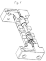
- Figure 5 shows a perspective view of how the system is constructed in practice.
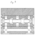
- Figures 6 and 7 show the two operating positions the system can assume.
- Pressure fluid for the last-mentioned movement is obtained from a second valve system consisting of a central part 40, a left-hand part 38 with a first electromagnet 50 and a right-hand part 39 with a second electromagnetic 52, two peripheral grooves 42 and 43 and an intermediate peripheral groove 44.
- the peripheral grooves 42 and 43 are connected to the connections 35 and 36.
- the valve system also comprises two valve bodies 45 and 46 connected by an intermediate portion 47.
- the valve bodies 45 and 46 are provided at each end with protruding rods 48 and 49. These rods constitute contact members for movable rods 51 and 53 included in the two electromagnets 50 and 52. Voltage is supplied to the two electromagnets via wires 57, 58 and 59, 60 from a voltage source 62.
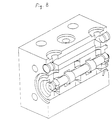
- FIG. 8 shows a practical embodiment of the second valve system in perspective and Figure 9 shows said valve system in section in a working position.
- the valves 45, 46, 47, 48 and 49 can move either to the right or the left.
- the electromagnets 50 and 52 are so chosen that they have an extremely short reaction time, lying between 2 and 3 milliseconds per stroke movement.
- the unit should also be made of light material such as a light metal and may be aluminium. This enables the pressure fluid supplied to the connections 35 and 36 to perform extremely rapid movements of the valve units 25, 26 and 27, so that the unit quickly opens the valve and the opening to the pressure-fluid container 64. The pressure fluid acting upwardly on the impact ram then quickly leaves the pressure surface 6 of the impact ram. This speed is also obtained since the fluid tapped off is able to escape quickly into a space formed in the peripheral groove 23a.
- the ram unit 25, 26 and 27 will assume its left-hand position.
- the ram unit is moved to the right, whereupon the lower contact surface is again placed under pressure.
- the impact ram 2 is returned to its upper position in approximately 15 milliseconds.
- a stroke frequency of about 3000 strokes/minute can be achieved with the present percussion machine, by allowing the switch 61 to continually change position.
- the switch can also be arranged so that a number of consecutive strokes is followed by an interval, and then another number of strokes and so on. The switch thus offers infinite possibilities for varying the stroke sequences.
- the desired kinetic energy is dependent on the oil pressure on the area of the upper contact surface 5, the weight of the striking body and of its stroke length. The energy required is determined by the material to be cut.
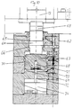
- Figure 10 shows a damping unit 62 with which the impact ram 2 can cooperate.
- the unit is provided with a ram 63 for returning the tool 13 which is provided with a surrounding band 64 having an upper contact surface for pressure fluid 65 and a lower contact surface 66 for pressure fluid.
- the transfer ram 63 cooperates with a damping ram 67 having a surrounding band 68 with an upper contact surface 70 for a pressure fluid and a lower contact surface 69 for a pressure fluid.
- the damping ram 67 has a central aperture 71 leading from its lower end surface.
- a ram 72 is arranged in this aperture in a predetermined, adjustable position.
- the rod is attached by its lower end to an adjustable unit 74, vertically movable to a desired position.
- the unit 74 may be adjusted either manually or automatically.
- the position of the unit 74 determines the cutting length of the tool 13.
- a disc 73 with a hole in it, the diameter of which allows passage of the ram 72, is secured in the lower end of the central aperture 71.
- the thickness of the disc is greater than the width of a peripheral groove of the ram 72, said peripheral groove having an outlet opening for pressure liquid that runs in the centre of the ram 72.
- the position of the damping ram 67 is fixed by the position of the peripheral groove of the ram 72. Furthermore, the actual damping effect of the damping unit is achieved by means of the oil layer appearing below the damping ram 67.
Landscapes
- Engineering & Computer Science (AREA)
- Mechanical Engineering (AREA)
- Manufacturing & Machinery (AREA)
- Percussive Tools And Related Accessories (AREA)
- Crushing And Pulverization Processes (AREA)
- Portable Nailing Machines And Staplers (AREA)
- Developing Agents For Electrophotography (AREA)
- Physical Or Chemical Processes And Apparatus (AREA)
- Actuator (AREA)
- Fluid-Pressure Circuits (AREA)
- Press Drives And Press Lines (AREA)
- Valve Device For Special Equipments (AREA)
Abstract
Description
- Figure 1
- shows a housing with impact ram and tool arrangement for cutting metal rods,
- Figure 2
- shows an arrangement for regulating the stroke length of the impact ram,
- Figure 3
- shows part of an arrangement according to Figure 1 during a stroke,
- Figure 4
- shows a general diagram of a percussion machine,
- Figure 5
- shows a perspective view of a first valve system,
- Figures 6-7
- shows a cross section of the valve system shown in Figure 5 in two different operating situations,
- Figure 8
- shows a perspective view of a second valve system,
- Figure 9
- shows a cross section of the valve system shown in Figure 8 in one functioning position.
- Figure 10
- shows a longitudinal section of a damping unit,
Claims (18)
- A percussion machine with a striking unit provided with a tool which, when functioning, emits kinetic energy of such magnitude that metallic material can be machined with minimum changes in material and with no materials loss,
charaterized in that the striking unit has an impact ram (2) movable between two end positions with two circumferential surfaces (5 and 6) perpendicular to the axis of the impact ram (2), which surfaces (5 and 6) can be acted upon by liquid pressure and are of different sizes, whereby one of the surfaces (5) is providing the working stroke and is smaller than the other (6) which provides the return stroke, the pressure on the smaller circumferential surface being exerted continuously, and the space where the pressure acting on the larger circumferential surface (6) is built up, being provided with an outlet-inlrt (8) regulated by a first valve system having body parts (25 and 26) being movable by pressure fluid and controlling the discharge from and the feeding of pressure fluid to said space, whereby preferably adiabatic coalescence occurs. - A percussion machine as claimed in claim 1,
characterized in that the distance between the two end positions is adjustable. - A percussion machine as claimed in claim 1,
characterized in that kinetic energy emitted upon a stroke is dependent on the liquid pressure acting on the smaller circumferential surfaces (5), the impact ram mass (2) and the stroke length, and has a value set for predetermined machining. - A percussion machine as claimed in claim 1,
characterized in that the liquid pressure is supplied to the smaller circumferential surface (5) via a hydro-pneumatic accumulator (17). - A percussion machine as claimed in claim 4
characterized in that when open, the unit (25) communicates with an outlet channel (23a). - A percussion machine as claimed in claim 1,
characterized in that the impact ram (2) is hollow and contains a second impact ram that can be influenced by pressure fluid, preferably in the same manner as the surrounding ram, the second ram influencing the striking function of the hallow ram by means, for example, of a supplementary stroke. - A percussion machine as claimed in claim 1,
characterized in that a valve housing (19) comprising a cylindrical through-hole (22) and two valve bodies (25 and 26) arranged one after the other in the hole (22) and joined by a connecting rod (27), three annular recesses arranged one after the other, spaced from each other and perpendicular to the hole (22), said recesses (23a, 23b and 24) preferably having quadric cross section and communicating with pressure medium, the two outer grooves (23a and 24) being designed to form valves with the two valve bodies (25 and 26). - A percussion machine as claimed in claim 7,
characterized in that the length of at least one sealing ram (25) is considerably greater than the width of the cooperating recess (23a). - A percussion machine as claimed in claim 7,
charaterized by means such as fluid or electromagnets (50 and 52) to displace the rams (25 and 26). - A percussion machine as claimed in claim 7,
characterized in that the ram unit (25, 26 and 27) is manufactured out of material such as aluminium in order to achieve fast displacement. - A percussion machine as claimed in claim 1,
charaterized by the valve system in which the middle groove (23b) communicates with the space by the impact ram (2) where the pressure acting on the large circumferential surface (6) is built up, whereas the outer grooves (23a and 24) are in communication with a liquid outlet (63) and the inlet (34). - A percussion as claimed in claim 1,
characterized in that the middle groove (44) of a pilot valve system communicates with a liquid inlet (37) and the outer grooves (42 and 43) are in communication with each of the two rams (28 and 29) in said valve system for their displacement. - A percussion machine as claimed in claim 12,
characterized in that in order to control their movement in one or the other direction, the two rams (45 and 46) with their connecting rod (47) in said pilot valve system receive a force from one of two electromagnets (20 and 52) influenced by a switch (61) that is preferably computer-controlled. - A percussion machine as claimed in claim 13,
charaterized in that the switch (61) can be actuated in many different way;, such as continual switching or switching with intervals. - A percussion machine as claimed in claim 1,
characterized by a cooperating damping means with a ram (63) for transmitting strokes from said impact ram (2) to a damping ram (67), both the rams (63 and 67) being influenced by pressure fluid in the same way as said impact ram (2). - A percussion machine as claimed in claim 15
charaterized by an adjusting unit (74), preferably computer-controlled, influencing the stroke length of said tool (13) by adjustment of the damping ram (67). - A percussion machine as claimed in claim 16,
characterized by a damping ram (63) adjusting the hydraulic valve (72 and 73) - A percussion machine as claimed in claim 17,
characterized by a disc (73) with a central aperture, arranged at the lower end of the damping ram (67), into which aperture an adjustable ram (72) is insert, having a peripheral groove with an outlet for pressure fluid, said outlet running in the longitudinal direction of adjustable ram.
Priority Applications (1)
| Application Number | Priority Date | Filing Date | Title |
|---|---|---|---|
| EP99201307A EP0968785B1 (en) | 1995-06-21 | 1995-06-21 | Method and tool for a percussion machine |
Applications Claiming Priority (1)
| Application Number | Priority Date | Filing Date | Title |
|---|---|---|---|
| PCT/SE1995/000758 WO1997000751A1 (en) | 1995-06-21 | 1995-06-21 | Impact machine |
Related Child Applications (1)
| Application Number | Title | Priority Date | Filing Date |
|---|---|---|---|
| EP99201307A Division EP0968785B1 (en) | 1995-06-21 | 1995-06-21 | Method and tool for a percussion machine |
Publications (2)
| Publication Number | Publication Date |
|---|---|
| EP0833714A1 EP0833714A1 (en) | 1998-04-08 |
| EP0833714B1 true EP0833714B1 (en) | 2000-10-25 |
Family
ID=20397411
Family Applications (1)
| Application Number | Title | Priority Date | Filing Date |
|---|---|---|---|
| EP95926552A Expired - Lifetime EP0833714B1 (en) | 1995-06-21 | 1995-06-21 | Impact machine |
Country Status (9)
| Country | Link |
|---|---|
| US (1) | US6202757B1 (en) |
| EP (1) | EP0833714B1 (en) |
| JP (1) | JPH11508187A (en) |
| AT (1) | ATE197131T1 (en) |
| AU (1) | AU3088695A (en) |
| DE (1) | DE69519238T2 (en) |
| DK (1) | DK0833714T3 (en) |
| ES (1) | ES2154341T3 (en) |
| WO (1) | WO1997000751A1 (en) |
Families Citing this family (29)
| Publication number | Priority date | Publication date | Assignee | Title |
|---|---|---|---|---|
| SE514893C2 (en) * | 1998-11-18 | 2001-05-14 | Hydropulsor Ab | Method and device for impact on a moving object |
| SE513170C2 (en) * | 1998-11-19 | 2000-07-17 | Hydropulsor Ab | Material and device for defromation of a material body |
| SE515042C2 (en) | 1999-10-19 | 2001-06-05 | Hydropulsor Ab | Percussion device and method for cutting and forming a blank |
| SE9903812D0 (en) | 1999-10-22 | 1999-10-22 | Skf Nova Ab | A forming tool |
| SE0002770D0 (en) * | 2000-07-25 | 2000-07-25 | Biomat System Ab | a method of producing a body by adiabatic forming and the body produced |
| US6537489B2 (en) | 2000-11-09 | 2003-03-25 | Höganäs Ab | High density products and method for the preparation thereof |
| SE0004122D0 (en) * | 2000-11-09 | 2000-11-09 | Hoeganaes Ab | High density compacts and method for the preparation thereof |
| SE520460C2 (en) * | 2001-05-10 | 2003-07-15 | Morphic Technologies Ab | Apparatus and method of material processing using high kinetic energy |
| SE0102103D0 (en) | 2001-06-13 | 2001-06-13 | Hoeganaes Ab | High density soft magnetic products and method for the preparation thereof |
| SE0102102D0 (en) * | 2001-06-13 | 2001-06-13 | Hoeganaes Ab | High density stainless steel products and method of preparation thereof |
| BR0307212A (en) * | 2002-01-25 | 2006-04-11 | Ck Man Ab | process for producing high density and speed compaction |
| KR100461236B1 (en) * | 2002-01-26 | 2004-12-14 | 주식회사 라이지오케미칼코리아 | Soil cover composite for refuse landfill and method of manafacture |
| DE10255753A1 (en) * | 2002-11-28 | 2004-06-09 | Menck Gmbh | Ram device for driving in piles has distance between separable pile guide's lower end and hammer cover smaller than twice internal diameter of pile guide, preferably less than half internal diameter |
| ITMI20030057A1 (en) * | 2003-01-17 | 2004-07-18 | Ficep Spa | DEVICE FOR CUTTING METAL MATERIALS BELOW |
| US20060266173A1 (en) * | 2003-03-04 | 2006-11-30 | Helmut Schuster | Impact cutting device and cutting unit therefor |
| FR2859935B1 (en) * | 2003-09-19 | 2006-02-10 | Adiapress | ENERGY DAMPING METHOD AND DEVICE FOR MACHINES USING ADIABATIC ENERGY TRANSFORMATION |
| SE525853C2 (en) * | 2003-09-25 | 2005-05-17 | Hydropulsor Ab | Method and apparatus for forming powdered material |
| ATE410256T1 (en) * | 2003-10-01 | 2008-10-15 | Helmut Schuster | CUTTING UNIT FOR AN IMPACT CUTTING DEVICE |
| US20050129562A1 (en) * | 2003-10-17 | 2005-06-16 | Hoganas Ab | Method for the manufacturing of sintered metal parts |
| FR2866823B1 (en) * | 2004-02-27 | 2007-05-04 | Arcelor Negoce Distrib | DAMPING DEVICE FOR MACHINE TOOL, MACHINE AND METHOD OF ADIABATIC CUTTING WITH VERY HIGH CADENCE |
| US20080202651A1 (en) * | 2004-11-25 | 2008-08-28 | Jfe Steel Corporation | Method For Manufacturing High-Density Iron-Based Compacted Body and High-Density Iron-Based Sintered Body |
| SE528257C2 (en) * | 2005-10-28 | 2006-10-03 | Hydropulsor Ab | Preventing crack formation in metal rods during high speed percussive cutting, comprises heating region of rod to be cut to specific temperature |
| US20100092328A1 (en) * | 2008-10-09 | 2010-04-15 | Glenn Thomas | High velocity adiabatic impact powder compaction |
| DE102009037396B4 (en) | 2009-08-13 | 2012-08-16 | Wafios Ag | Pyrotechnically operated cutting device |
| EP2511031A1 (en) | 2011-04-12 | 2012-10-17 | Höganäs Ab (publ) | A powder metallurgical composition and sintered component |
| SE537946C2 (en) | 2014-03-24 | 2015-12-01 | Cell Impact Ab | Impact and method of material processing with high kinetic energy utilization |
| US20160186304A1 (en) * | 2014-10-31 | 2016-06-30 | Adiabatic Solutions, Llc | Increasing The Strength Of Metals And Metal Components |
| CN106907365B (en) * | 2017-03-16 | 2018-07-24 | 辽宁工程技术大学 | A kind of coal petrography presplitting relief arrangement and its control method |
| US20210065942A1 (en) * | 2017-12-22 | 2021-03-04 | Querdenkfabrik Ag | Method for the production of a soft magnetic formed part and soft magnetic formed part |
Family Cites Families (5)
| Publication number | Priority date | Publication date | Assignee | Title |
|---|---|---|---|---|
| GB546875A (en) * | 1941-03-28 | 1942-08-04 | William Jenny Riddle | Improvements in hydraulic cutting machines |
| IL78698A (en) * | 1986-05-06 | 1990-11-05 | Goldman Giora | Hydraulic-pneumatic actuator for impact cutter |
| DE4028595A1 (en) * | 1990-09-08 | 1992-03-12 | Krupp Maschinentechnik | HYDRAULICALLY OPERATED PERFORMANCE |
| FR2676953B1 (en) * | 1991-05-30 | 1993-08-20 | Montabert Ets | HYDRAULIC PERCUSSION APPARATUS. |
| DE4420682A1 (en) * | 1994-06-14 | 1996-01-04 | Rexroth Mannesmann Gmbh | Hydraulic control for a dividing machine tool |
-
1995
- 1995-06-21 US US08/973,548 patent/US6202757B1/en not_active Expired - Fee Related
- 1995-06-21 EP EP95926552A patent/EP0833714B1/en not_active Expired - Lifetime
- 1995-06-21 ES ES95926552T patent/ES2154341T3/en not_active Expired - Lifetime
- 1995-06-21 AU AU30886/95A patent/AU3088695A/en not_active Abandoned
- 1995-06-21 DE DE69519238T patent/DE69519238T2/en not_active Expired - Fee Related
- 1995-06-21 DK DK95926552T patent/DK0833714T3/en active
- 1995-06-21 WO PCT/SE1995/000758 patent/WO1997000751A1/en not_active Ceased
- 1995-06-21 AT AT95926552T patent/ATE197131T1/en not_active IP Right Cessation
- 1995-06-21 JP JP9503767A patent/JPH11508187A/en not_active Ceased
Also Published As
| Publication number | Publication date |
|---|---|
| ATE197131T1 (en) | 2000-11-15 |
| EP0833714A1 (en) | 1998-04-08 |
| AU3088695A (en) | 1997-01-22 |
| DK0833714T3 (en) | 2001-03-05 |
| DE69519238D1 (en) | 2000-11-30 |
| ES2154341T3 (en) | 2001-04-01 |
| JPH11508187A (en) | 1999-07-21 |
| WO1997000751A1 (en) | 1997-01-09 |
| US6202757B1 (en) | 2001-03-20 |
| DE69519238T2 (en) | 2001-06-07 |
Similar Documents
| Publication | Publication Date | Title |
|---|---|---|
| EP0833714B1 (en) | Impact machine | |
| GB1584384A (en) | Method and apparatus for controlling a press plunger system | |
| CA1056224A (en) | Method and apparatus for the shock pressure shaping | |
| KR101118941B1 (en) | Impact device and method for generating stress pulse therein | |
| KR20060054289A (en) | A method of generating stress pulses to a tool by means of a pressure fluid actuated impact device and the impact device | |
| SU1641597A1 (en) | Device for strengthening and finish-machining surfaces of holes | |
| US4509330A (en) | Pneumatically controlled pressure transducer for operating hydraulic work tools | |
| US6764644B2 (en) | Method of using an impact machine | |
| EP0968785B1 (en) | Method and tool for a percussion machine | |
| US3271991A (en) | High energy impact machine | |
| US4479551A (en) | Actuator for a hydraulic impact device | |
| US3898834A (en) | High energy forging press | |
| US4144904A (en) | Control device for the speed control of pneumatic and/or hydraulic working pistons | |
| US6901842B2 (en) | Percussion hydraulic apparatus | |
| US4397175A (en) | Apparatus for controlling the movement of a reciprocatory hydraulically driven element | |
| EP0461184A1 (en) | CONTROL ARRANGEMENT AND METHOD FOR PROGRESSIVELY BREAKING PIECES TO BE TREATED. | |
| DE19545708A1 (en) | Method for influencing the operating behavior of a fluid-operated hammer mechanism and hammer mechanism suitable for carrying out the method | |
| SU804165A1 (en) | Vibration rress with hydraulic drive | |
| US3636808A (en) | Material-cutting machine | |
| US5176054A (en) | Control apparatus and method for progressive fracture of workpieces | |
| DE19613128C2 (en) | Machine tool with a device which can be actuated by a piston-cylinder unit | |
| GB2175648A (en) | Pressure intensifier hydraulic cylinder system | |
| US3930435A (en) | Hydraulically powered actuator | |
| SU1265015A1 (en) | Pneumohydraulic shears | |
| SU1268258A1 (en) | Arrangement for feeding unit blanks to the machining zone and removing parts and waste |
Legal Events
| Date | Code | Title | Description |
|---|---|---|---|
| PUAI | Public reference made under article 153(3) epc to a published international application that has entered the european phase |
Free format text: ORIGINAL CODE: 0009012 |
|
| 17P | Request for examination filed |
Effective date: 19980116 |
|
| AK | Designated contracting states |
Kind code of ref document: A1 Designated state(s): AT BE CH DE DK ES FR GB GR IE IT LI LU MC NL PT SE |
|
| 17Q | First examination report despatched |
Effective date: 19981228 |
|
| GRAG | Despatch of communication of intention to grant |
Free format text: ORIGINAL CODE: EPIDOS AGRA |
|
| GRAG | Despatch of communication of intention to grant |
Free format text: ORIGINAL CODE: EPIDOS AGRA |
|
| GRAG | Despatch of communication of intention to grant |
Free format text: ORIGINAL CODE: EPIDOS AGRA |
|
| GRAH | Despatch of communication of intention to grant a patent |
Free format text: ORIGINAL CODE: EPIDOS IGRA |
|
| GRAH | Despatch of communication of intention to grant a patent |
Free format text: ORIGINAL CODE: EPIDOS IGRA |
|
| GRAA | (expected) grant |
Free format text: ORIGINAL CODE: 0009210 |
|
| AK | Designated contracting states |
Kind code of ref document: B1 Designated state(s): AT BE CH DE DK ES FR GB GR IE IT LI LU MC NL PT SE |
|
| REF | Corresponds to: |
Ref document number: 197131 Country of ref document: AT Date of ref document: 20001115 Kind code of ref document: T |
|
| REG | Reference to a national code |
Ref country code: CH Ref legal event code: EP |
|
| REG | Reference to a national code |
Ref country code: IE Ref legal event code: FG4D |
|
| REF | Corresponds to: |
Ref document number: 69519238 Country of ref document: DE Date of ref document: 20001130 |
|
| ITF | It: translation for a ep patent filed | ||
| PG25 | Lapsed in a contracting state [announced via postgrant information from national office to epo] |
Ref country code: PT Free format text: LAPSE BECAUSE OF FAILURE TO SUBMIT A TRANSLATION OF THE DESCRIPTION OR TO PAY THE FEE WITHIN THE PRESCRIBED TIME-LIMIT Effective date: 20010125 |
|
| PG25 | Lapsed in a contracting state [announced via postgrant information from national office to epo] |
Ref country code: GR Free format text: LAPSE BECAUSE OF FAILURE TO SUBMIT A TRANSLATION OF THE DESCRIPTION OR TO PAY THE FEE WITHIN THE PRESCRIBED TIME-LIMIT Effective date: 20010126 |
|
| ET | Fr: translation filed | ||
| REG | Reference to a national code |
Ref country code: CH Ref legal event code: NV Representative=s name: PATENTANWAELTE SCHAAD, BALASS, MENZL & PARTNER AG |
|
| REG | Reference to a national code |
Ref country code: DK Ref legal event code: T3 |
|
| REG | Reference to a national code |
Ref country code: ES Ref legal event code: FG2A Ref document number: 2154341 Country of ref document: ES Kind code of ref document: T3 |
|
| PG25 | Lapsed in a contracting state [announced via postgrant information from national office to epo] |
Ref country code: LU Free format text: LAPSE BECAUSE OF NON-PAYMENT OF DUE FEES Effective date: 20010621 Ref country code: IE Free format text: LAPSE BECAUSE OF NON-PAYMENT OF DUE FEES Effective date: 20010621 |
|
| PG25 | Lapsed in a contracting state [announced via postgrant information from national office to epo] |
Ref country code: MC Free format text: LAPSE BECAUSE OF NON-PAYMENT OF DUE FEES Effective date: 20010630 |
|
| PLBE | No opposition filed within time limit |
Free format text: ORIGINAL CODE: 0009261 |
|
| STAA | Information on the status of an ep patent application or granted ep patent |
Free format text: STATUS: NO OPPOSITION FILED WITHIN TIME LIMIT |
|
| 26N | No opposition filed | ||
| REG | Reference to a national code |
Ref country code: GB Ref legal event code: IF02 |
|
| PGFP | Annual fee paid to national office [announced via postgrant information from national office to epo] |
Ref country code: BE Payment date: 20051128 Year of fee payment: 11 |
|
| PGFP | Annual fee paid to national office [announced via postgrant information from national office to epo] |
Ref country code: NL Payment date: 20051130 Year of fee payment: 11 |
|
| PG25 | Lapsed in a contracting state [announced via postgrant information from national office to epo] |
Ref country code: BE Free format text: LAPSE BECAUSE OF NON-PAYMENT OF DUE FEES Effective date: 20060630 |
|
| PGFP | Annual fee paid to national office [announced via postgrant information from national office to epo] |
Ref country code: AT Payment date: 20061222 Year of fee payment: 12 |
|
| PGFP | Annual fee paid to national office [announced via postgrant information from national office to epo] |
Ref country code: DK Payment date: 20061228 Year of fee payment: 12 |
|
| PG25 | Lapsed in a contracting state [announced via postgrant information from national office to epo] |
Ref country code: NL Free format text: LAPSE BECAUSE OF NON-PAYMENT OF DUE FEES Effective date: 20070101 |
|
| NLV4 | Nl: lapsed or anulled due to non-payment of the annual fee |
Effective date: 20070101 |
|
| BERE | Be: lapsed |
Owner name: *HYDROPULSOR A.B. Effective date: 20060630 |
|
| REG | Reference to a national code |
Ref country code: DK Ref legal event code: EBP |
|
| PG25 | Lapsed in a contracting state [announced via postgrant information from national office to epo] |
Ref country code: AT Free format text: LAPSE BECAUSE OF NON-PAYMENT OF DUE FEES Effective date: 20070621 |
|
| PG25 | Lapsed in a contracting state [announced via postgrant information from national office to epo] |
Ref country code: DK Free format text: LAPSE BECAUSE OF NON-PAYMENT OF DUE FEES Effective date: 20070702 |
|
| PGFP | Annual fee paid to national office [announced via postgrant information from national office to epo] |
Ref country code: FR Payment date: 20090630 Year of fee payment: 15 Ref country code: ES Payment date: 20090630 Year of fee payment: 15 Ref country code: CH Payment date: 20090630 Year of fee payment: 15 |
|
| PGFP | Annual fee paid to national office [announced via postgrant information from national office to epo] |
Ref country code: SE Payment date: 20090630 Year of fee payment: 15 Ref country code: GB Payment date: 20090630 Year of fee payment: 15 Ref country code: DE Payment date: 20090825 Year of fee payment: 15 |
|
| PGFP | Annual fee paid to national office [announced via postgrant information from national office to epo] |
Ref country code: IT Payment date: 20090630 Year of fee payment: 15 |
|
| REG | Reference to a national code |
Ref country code: CH Ref legal event code: PL |
|
| EUG | Se: european patent has lapsed | ||
| GBPC | Gb: european patent ceased through non-payment of renewal fee |
Effective date: 20100621 |
|
| REG | Reference to a national code |
Ref country code: FR Ref legal event code: ST Effective date: 20110228 |
|
| PG25 | Lapsed in a contracting state [announced via postgrant information from national office to epo] |
Ref country code: IT Free format text: LAPSE BECAUSE OF NON-PAYMENT OF DUE FEES Effective date: 20100621 |
|
| PG25 | Lapsed in a contracting state [announced via postgrant information from national office to epo] |
Ref country code: LI Free format text: LAPSE BECAUSE OF NON-PAYMENT OF DUE FEES Effective date: 20100630 Ref country code: CH Free format text: LAPSE BECAUSE OF NON-PAYMENT OF DUE FEES Effective date: 20100630 Ref country code: DE Free format text: LAPSE BECAUSE OF NON-PAYMENT OF DUE FEES Effective date: 20110101 |
|
| PG25 | Lapsed in a contracting state [announced via postgrant information from national office to epo] |
Ref country code: FR Free format text: LAPSE BECAUSE OF NON-PAYMENT OF DUE FEES Effective date: 20100630 |
|
| REG | Reference to a national code |
Ref country code: ES Ref legal event code: FD2A Effective date: 20110718 |
|
| PG25 | Lapsed in a contracting state [announced via postgrant information from national office to epo] |
Ref country code: ES Free format text: LAPSE BECAUSE OF NON-PAYMENT OF DUE FEES Effective date: 20110706 Ref country code: GB Free format text: LAPSE BECAUSE OF NON-PAYMENT OF DUE FEES Effective date: 20100621 |
|
| PG25 | Lapsed in a contracting state [announced via postgrant information from national office to epo] |
Ref country code: ES Free format text: LAPSE BECAUSE OF NON-PAYMENT OF DUE FEES Effective date: 20100622 |
|
| PG25 | Lapsed in a contracting state [announced via postgrant information from national office to epo] |
Ref country code: SE Free format text: LAPSE BECAUSE OF NON-PAYMENT OF DUE FEES Effective date: 20100622 |