EP0833708B1 - Procede de fabrication d'un recipient de cuisson a double paroi par frappe a chaud et recipient fabrique selon ce procede - Google Patents
Procede de fabrication d'un recipient de cuisson a double paroi par frappe a chaud et recipient fabrique selon ce procede Download PDFInfo
- Publication number
- EP0833708B1 EP0833708B1 EP96922968A EP96922968A EP0833708B1 EP 0833708 B1 EP0833708 B1 EP 0833708B1 EP 96922968 A EP96922968 A EP 96922968A EP 96922968 A EP96922968 A EP 96922968A EP 0833708 B1 EP0833708 B1 EP 0833708B1
- Authority
- EP
- European Patent Office
- Prior art keywords
- vessel
- hot stamping
- bowl
- double
- tank
- Prior art date
- Legal status (The legal status is an assumption and is not a legal conclusion. Google has not performed a legal analysis and makes no representation as to the accuracy of the status listed.)
- Expired - Lifetime
Links
Images


Classifications
-
- B—PERFORMING OPERATIONS; TRANSPORTING
- B21—MECHANICAL METAL-WORKING WITHOUT ESSENTIALLY REMOVING MATERIAL; PUNCHING METAL
- B21D—WORKING OR PROCESSING OF SHEET METAL OR METAL TUBES, RODS OR PROFILES WITHOUT ESSENTIALLY REMOVING MATERIAL; PUNCHING METAL
- B21D51/00—Making hollow objects
- B21D51/16—Making hollow objects characterised by the use of the objects
- B21D51/18—Making hollow objects characterised by the use of the objects vessels, e.g. tubs, vats, tanks, sinks, or the like
- B21D51/22—Making hollow objects characterised by the use of the objects vessels, e.g. tubs, vats, tanks, sinks, or the like pots, e.g. for cooking
-
- A—HUMAN NECESSITIES
- A47—FURNITURE; DOMESTIC ARTICLES OR APPLIANCES; COFFEE MILLS; SPICE MILLS; SUCTION CLEANERS IN GENERAL
- A47J—KITCHEN EQUIPMENT; COFFEE MILLS; SPICE MILLS; APPARATUS FOR MAKING BEVERAGES
- A47J27/00—Cooking-vessels
- A47J27/002—Construction of cooking-vessels; Methods or processes of manufacturing specially adapted for cooking-vessels
-
- B—PERFORMING OPERATIONS; TRANSPORTING
- B23—MACHINE TOOLS; METAL-WORKING NOT OTHERWISE PROVIDED FOR
- B23K—SOLDERING OR UNSOLDERING; WELDING; CLADDING OR PLATING BY SOLDERING OR WELDING; CUTTING BY APPLYING HEAT LOCALLY, e.g. FLAME CUTTING; WORKING BY LASER BEAM
- B23K20/00—Non-electric welding by applying impact or other pressure, with or without the application of heat, e.g. cladding or plating
- B23K20/02—Non-electric welding by applying impact or other pressure, with or without the application of heat, e.g. cladding or plating by means of a press ; Diffusion bonding
- B23K20/023—Thermo-compression bonding
-
- B—PERFORMING OPERATIONS; TRANSPORTING
- B23—MACHINE TOOLS; METAL-WORKING NOT OTHERWISE PROVIDED FOR
- B23K—SOLDERING OR UNSOLDERING; WELDING; CLADDING OR PLATING BY SOLDERING OR WELDING; CUTTING BY APPLYING HEAT LOCALLY, e.g. FLAME CUTTING; WORKING BY LASER BEAM
- B23K2101/00—Articles made by soldering, welding or cutting
- B23K2101/04—Tubular or hollow articles
- B23K2101/12—Vessels
Definitions
- the present invention relates to the technical field of containers for double wall cooking in general and it applies more particularly to pressure cookers having such a double wall configuration.
- WO 87/04911 describes a container comprising a tank, a intermediate bottom element and a bottom plate assembled by striking with hot.
- WO 88/03379 describes a cooking vessel, comprising a tank, an intermediate bottom element and a counter tank, assembled by soldering or welding.
- document FR-A-2 437 184 describes a double-walled container made by stamping a plate with two walls separated by a soul. This manufacturing method involves significant difficulties in terms of separation and final shaping of the walls. In addition, it is necessary that an intermediate material occupies the entire surface between the walls.
- the object of the invention is precisely to remedy the drawbacks and / or the aforementioned limitations, and thus relates to a method of assembling a double-walled cooking vessel as defined in claim 1.
- Another object of the invention is to provide a double cooking container wall comprising a tank, a counter tank forming an inter-wall space with the tank, and a bottom intermediate element assembled with the face outside of the bottom of the tank and with the inside face of the bottom of the counter tank, characterized in that the bottom intermediate element is made of a metal hot deformed by creep, such a container can be obtained using the aforementioned process.
- the method according to the invention makes it possible to obtain a cost price particularly advantageous, with great flexibility in the modes of production.
- the container obtained has excellent thermal quality, hence a decrease in energy consumption. It offers great ease of use.
- the design of the container and the method of production make it relatively easy to change the profile of the outer wall, without affecting all the product concept. We can thus produce different series more or less important with differentiated profiles, changing only one element of the product.
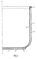
- the cooking container according to the present invention consists of a tank 1 advantageously of circular cylindrical profile.
- Figure 1 illustrates an example of a container shaped around an x-x axis.
- the tank 1 is preferably made of stainless steel alloy formed in a known manner, for example by stamping. According to various variants, it is also possible to manufacture tank 1 in colaminated materials (aluminum / stainless steel with two or several thicknesses) or aluminum.
- Counter tank 2 is also advantageously made of an alloy stainless steel, but in various variants it can be from another type of material, such as copper or colaminated.
- the profile as well as the dimensions of the counter-tank are provided for so that it can accommodate at least one intermediate piece of bottom 3 and tank 1.
- the tanks 1 and 2 are shaped so as to delimit a space inter-walls 5 preferably extending over almost the entire height of the walls and around the entire circumference of the container. On the example illustrated in Figure 1, space 5 is occupied by air. In order to improve the characteristics thermal insulation between the two walls, it is possible to have in this space one or more layers of insulating material.
- the ledges walls of the two tanks are advantageously fixed together and advantageously folded towards the outside of the tank so as to form a border 4, either by welding, crimping or rolling, so as to provide a rigid and durable support.
- the fixing of the edges is advantageously waterproof, to prevent any liquid or foreign matter from entering space 5.
- the base 7 of the counter-tank serving as the bottom of the container, is preferably flat and may include openings 8 distributed over said surface of the base 7, through which metal will be introduced during hot stamping flowed from the intermediate element 3. This interpenetration between the two materials increases the mechanical cohesion between the tank 2 and the element 3 while promoting thermal conductivity.
- the resulting assembly includes therefore excellent rigidity and durability characteristics.
- the intermediate element 3 advantageously consists of a disc metallic alloy preferably easily malleable and conductive, such as aluminum or copper. The effect of hot stamping on this disc is described below.
- the assembly method according to the present invention consists in disposing the intermediate element 3 in the counter-tank 2 preferably by fixing it temporarily against the bottom thereof by means of known type, such as for example by welding, gluing, etc.
- This prefixing is desirable, in order facilitate handling and centering of the assembly to proceed easily in the following steps.
- the tank 1 is then introduced into the counter-tank, to be in turn arranged against element 3.
- the pre-assembled container is heated to the temperature at which it strikes hot will be performed.
- This temperature varies depending on the type of alloys used as well as according to other parameters such as for example the thickness of the metal walls. Generally, it is preferably between 400 ° C. and 500 ° C.
- the hot stamping is carried out at a temperature favoring the creep of the material constituting the intermediate element 3. It is obviously possible to heat the constituent elements separately and carry out successively the preassembly and the striking by the after.
- the pre-assembled container is then placed on a punch 9, the profile of which corresponds to the desired final shape for the internal portion of the container.
- a matrix 10, advantageously of shape adapted to the desired final external profile of the container, is arranged above the assembly.
- the matrix set and punch is part of a device adapted to carry out the hot stamping of the container. It is preferably a high tonnage press of known type.
- the hot stamping is achieved by lowering the die 10 against the tank along arrow A, so as to exert a very strong pressure in a very short time interval, in the form of an impact.
- the pressure exerted allows the final shaping of the container. More specifically, the typing causes permanent deformation of the corresponding portion substantially at the bottom of the container.
- the intermediate element undergoes creep: the edges rise in part between the two walls as indicated by the arrows B in FIG. 2a.
- the Figure 2b illustrates the final result obtained after the strike.
- the upper edges of the container are advantageously fixed together, as described above.
- FIG. 3 does not differ from those shown in FIGS. 1 and 2 only by a particular conformation of the counter-tank which comprises a reason 6 particular. We see that it is possible to achieve a multitude of different versions simply by providing a specific profile for each series of counter-tanks.
- the invention finds its application in the technical field of double wall cooking in general and it applies more particularly to pressure cookers having such a double wall configuration.
Description
Claims (11)
- Procédé d'assemblage d'un récipient de cuisson à double paroi comportant une cuve (1) interne, un élément intermédiaire de fond (3) et une contre cuve (2) formant un espace inter parois (5) avec la cuve (1), caractérisé en ce qu'il consiste à disposer sur un poinçon (9) la cuve (1), l'élément intermédiaire de fond (3) et la contre cuve (2), la cuve (1) et la contre cuve (2) étant préformées de manière à former l'espace inter parois (5), l'élément intermédiaire de fond (3) étant réalisé dans un métal susceptible de fluer à chaud, et à réaliser une frappe à chaud au moyen d'une matrice (10).
- Procédé selon la revendication 1, dans lequel l'ensemble (2, 3, 1) à frapper est préchauffé à une température définie.
- Procédé selon l'une des revendications précédentes, dans lequel la frappe occasionne une déformation permanente de la portion correspondant sensiblement au fond du récipient.
- Procédé selon l'une des revendications précédentes, dans lequel la frappe à chaud est réalisée à une température favorisant le fluage du matériau constituant l'élément intermédiaire (3).
- Procédé selon la revendication 4, dans lequel ladite température se situe entre 400°C et 500°C.
- Procédé selon la revendication 1, dans lequel la frappe à chaud est réalisée au moyen d'un poinçon (9) et d'une matrice (10) adaptés au profil final prévu.
- Procédé selon l'une des revendications précédentes, dans lequel au moins deux des éléments (2, 3, 1) constituant ledit ensemble sont prépositionnés ou préassemblés avant la frappe à chaud par soudure ou collage.
- Récipient de cuisson à double paroi comportant une cuve (1), une contre cuve (2) formant un espace inter parois (5) avec la cuve (1), et un élément intermédiaire de fond (3) assemblé avec la face extérieure du fond de la cuve (1) et avec la face intérieure du fond de la contre cuve (2), caractérisé en ce que l'élément intermédiaire de fond (3) est réalisé dans un métal déformé à chaud par fluage.
- Récipient selon la revendication 8, dans lequel ledit espace (5) contient de l'air.
- Récipient selon la revendication 8, dans lequel ledit espace (5) contient un matériau isolant.
- Récipient selon l'une des revendications 8 à 10, consistant en un autocuiseur.
Applications Claiming Priority (3)
| Application Number | Priority Date | Filing Date | Title |
|---|---|---|---|
| FR9507679A FR2735708B1 (fr) | 1995-06-21 | 1995-06-21 | Procede de fabrication d'un recipient de cuisson a double paroi par frappe a chaud et recipient fabrique selon ce procede |
| FR9507679 | 1995-06-21 | ||
| PCT/FR1996/000965 WO1997000742A1 (fr) | 1995-06-21 | 1996-06-20 | Procede de fabrication d'un recipient de cuisson a double paroi par frappe a chaud et recipient fabrique selon ce procede |
Publications (2)
| Publication Number | Publication Date |
|---|---|
| EP0833708A1 EP0833708A1 (fr) | 1998-04-08 |
| EP0833708B1 true EP0833708B1 (fr) | 2001-05-23 |
Family
ID=9480409
Family Applications (1)
| Application Number | Title | Priority Date | Filing Date |
|---|---|---|---|
| EP96922968A Expired - Lifetime EP0833708B1 (fr) | 1995-06-21 | 1996-06-20 | Procede de fabrication d'un recipient de cuisson a double paroi par frappe a chaud et recipient fabrique selon ce procede |
Country Status (5)
| Country | Link |
|---|---|
| EP (1) | EP0833708B1 (fr) |
| AU (1) | AU6363696A (fr) |
| DE (1) | DE69612976D1 (fr) |
| FR (1) | FR2735708B1 (fr) |
| WO (1) | WO1997000742A1 (fr) |
Families Citing this family (7)
| Publication number | Priority date | Publication date | Assignee | Title |
|---|---|---|---|---|
| US6191393B1 (en) * | 1999-01-16 | 2001-02-20 | Jong Do Peter Park | Cooking utensil and manufacturing method therefor |
| EP1086775A1 (fr) * | 1999-09-23 | 2001-03-28 | Gräbener Pressensysteme GmbH & Co. KG | Méthode et appareil pour la fabrication d'un récipient de cuisson ayant un fond en colaminé |
| EP1163870A1 (fr) * | 2000-06-12 | 2001-12-19 | Tutto S.p.A. | Procédé de production de poêles par thermo-compression |
| KR20050083191A (ko) * | 2003-05-16 | 2005-08-26 | 김명석 | 조리용기의 삼중바닥 제조방법 |
| US7097064B2 (en) * | 2004-01-28 | 2006-08-29 | Meyer Intellectual Properties Limited | Double wall cooking vessel |
| CH709339A2 (de) * | 2014-03-04 | 2015-09-15 | Condeco Technologies Ag | Verfahren zur Herstellung eines doppelwandigen Kochgeschirrs in einem einzigen Tiefzieh-Prozessschritt. |
| KR102378888B1 (ko) * | 2017-09-14 | 2022-03-24 | 임덕재 | 과열방지센서가 구비된 가스레인지에 사용 가능한 이중 조리용기 |
Family Cites Families (4)
| Publication number | Priority date | Publication date | Assignee | Title |
|---|---|---|---|---|
| JPS6145710A (ja) * | 1984-08-08 | 1986-03-05 | 日本酸素株式会社 | 真空断熱調理器具の製造方法 |
| CH667790A5 (de) * | 1985-10-31 | 1988-11-15 | Kuhn Heinrich Metall | Kochtopf. |
| KR900000385B1 (ko) * | 1986-02-18 | 1990-01-25 | 주식회사 우성 | 삼중요철 바닥면을 가진 주방용기 및 그 제조방법 |
| WO1988003379A1 (fr) * | 1986-11-15 | 1988-05-19 | Heinrich Berndes Gmbh | Recipient en metal pour faire bouillir, rotir ou cuire |
-
1995
- 1995-06-21 FR FR9507679A patent/FR2735708B1/fr not_active Expired - Fee Related
-
1996
- 1996-06-20 DE DE69612976T patent/DE69612976D1/de not_active Expired - Lifetime
- 1996-06-20 AU AU63636/96A patent/AU6363696A/en not_active Abandoned
- 1996-06-20 WO PCT/FR1996/000965 patent/WO1997000742A1/fr active IP Right Grant
- 1996-06-20 EP EP96922968A patent/EP0833708B1/fr not_active Expired - Lifetime
Also Published As
| Publication number | Publication date |
|---|---|
| AU6363696A (en) | 1997-01-22 |
| DE69612976D1 (de) | 2001-06-28 |
| FR2735708A1 (fr) | 1996-12-27 |
| EP0833708A1 (fr) | 1998-04-08 |
| FR2735708B1 (fr) | 1997-08-14 |
| WO1997000742A1 (fr) | 1997-01-09 |
Similar Documents
| Publication | Publication Date | Title |
|---|---|---|
| EP0668040B1 (fr) | Récipient culinaire à fond renforcé et son procédé de fabrication | |
| EP0833708B1 (fr) | Procede de fabrication d'un recipient de cuisson a double paroi par frappe a chaud et recipient fabrique selon ce procede | |
| FR2745079A1 (fr) | Echangeur de chaleur a boite a fluide brasee, en particulier pour vehicule automobile | |
| EP1453687B1 (fr) | Disque de roue automobile, notamment pour vehicule de tourisme | |
| CH673082A5 (fr) | ||
| EP2986409A2 (fr) | Brasage sans outillage | |
| EP2554080B1 (fr) | Procédé de fabrication d'un récipient de cuisson à déformation contrôlée et récipient obtenu | |
| EP0028951B1 (fr) | Echangeur de chaleur comportant un faisceau de tubes débouchant dans des plaques collectrices reliées mécaniquement à des boîtes à eau | |
| FR2770632A1 (fr) | Echangeur de chaleur a collecteur renforce, notamment pour vehicule automobile | |
| WO2004081453A2 (fr) | Dispositif de cuisson dont l’emballage comprend une piece ornementale et procede de fabrication correspondant | |
| CA2244503C (fr) | Dispositif de fixation de pieces d'un appareil electromenager | |
| WO2008145927A1 (fr) | Article culinaire a portee amelioree et procede de fabrication | |
| EP0351913B1 (fr) | Organe de fixation tel que rivet, procédé d'assemblage et assemblage obtenu | |
| FR2741553A1 (fr) | Procede de fabrication d'un recipient de cuisson et recipient obtenu | |
| EP0807367B1 (fr) | Element chauffant avec plaque diffusante et procede d'assemblage dudit ensemble | |
| EP0048666B1 (fr) | Procédé pour fixer un capot sur une semelle de fer à repasser à vapeur, ébauche de capot s'y rapportant et fer à repasser | |
| EP1919334A1 (fr) | Ustensile de cuisson | |
| EP1861673B1 (fr) | Plaque collectrice améliorée, boite collectrice et échangeur de chaleur comportant une telle plaque collectrice | |
| FR2755887A1 (fr) | Procede de fabrication d'un recipient de cuisson et recipient ainsi obtenu | |
| EP0061368A1 (fr) | Elément de joint homocinétique du type tripode | |
| EP1881289B1 (fr) | Echangeur de chaleur à collecteur amélioré | |
| EP2483591B1 (fr) | Bouteille de gaz dual-phase ou complex-phase | |
| FR2876535A1 (fr) | Element chauffant | |
| EP0415819B1 (fr) | Couvercle métallique pour récipient étanche | |
| FR2984614A1 (fr) | Dispositif de connexion d'une cosse, organe destine a former la borne de connexion, ecrou apte a cooperer avec l'organe, et kit de connexion d'une cosse |
Legal Events
| Date | Code | Title | Description |
|---|---|---|---|
| PUAI | Public reference made under article 153(3) epc to a published international application that has entered the european phase |
Free format text: ORIGINAL CODE: 0009012 |
|
| 17P | Request for examination filed |
Effective date: 19971222 |
|
| AK | Designated contracting states |
Kind code of ref document: A1 Designated state(s): DE ES GB IT PT |
|
| 17Q | First examination report despatched |
Effective date: 19980320 |
|
| GRAG | Despatch of communication of intention to grant |
Free format text: ORIGINAL CODE: EPIDOS AGRA |
|
| GRAG | Despatch of communication of intention to grant |
Free format text: ORIGINAL CODE: EPIDOS AGRA |
|
| GRAH | Despatch of communication of intention to grant a patent |
Free format text: ORIGINAL CODE: EPIDOS IGRA |
|
| GRAH | Despatch of communication of intention to grant a patent |
Free format text: ORIGINAL CODE: EPIDOS IGRA |
|
| GRAA | (expected) grant |
Free format text: ORIGINAL CODE: 0009210 |
|
| AK | Designated contracting states |
Kind code of ref document: B1 Designated state(s): DE ES GB IT PT |
|
| PG25 | Lapsed in a contracting state [announced via postgrant information from national office to epo] |
Ref country code: GB Free format text: LAPSE BECAUSE OF FAILURE TO SUBMIT A TRANSLATION OF THE DESCRIPTION OR TO PAY THE FEE WITHIN THE PRESCRIBED TIME-LIMIT Effective date: 20010523 |
|
| REF | Corresponds to: |
Ref document number: 69612976 Country of ref document: DE Date of ref document: 20010628 |
|
| PG25 | Lapsed in a contracting state [announced via postgrant information from national office to epo] |
Ref country code: DE Free format text: LAPSE BECAUSE OF NON-PAYMENT OF DUE FEES Effective date: 20010630 |
|
| ITF | It: translation for a ep patent filed |
Owner name: MAROSCIA & ASSOCIATI S.R.L. |
|
| PG25 | Lapsed in a contracting state [announced via postgrant information from national office to epo] |
Ref country code: PT Free format text: LAPSE BECAUSE OF FAILURE TO SUBMIT A TRANSLATION OF THE DESCRIPTION OR TO PAY THE FEE WITHIN THE PRESCRIBED TIME-LIMIT Effective date: 20010823 |
|
| GBV | Gb: ep patent (uk) treated as always having been void in accordance with gb section 77(7)/1977 [no translation filed] |
Effective date: 20010523 |
|
| PG25 | Lapsed in a contracting state [announced via postgrant information from national office to epo] |
Ref country code: ES Free format text: LAPSE BECAUSE OF FAILURE TO SUBMIT A TRANSLATION OF THE DESCRIPTION OR TO PAY THE FEE WITHIN THE PRESCRIBED TIME-LIMIT Effective date: 20011130 |
|
| PLBE | No opposition filed within time limit |
Free format text: ORIGINAL CODE: 0009261 |
|
| STAA | Information on the status of an ep patent application or granted ep patent |
Free format text: STATUS: NO OPPOSITION FILED WITHIN TIME LIMIT |
|
| 26N | No opposition filed | ||
| PG25 | Lapsed in a contracting state [announced via postgrant information from national office to epo] |
Ref country code: IT Free format text: LAPSE BECAUSE OF NON-PAYMENT OF DUE FEES Effective date: 20050620 |