EP0833582B1 - Vanne de commande a plusieurs voies pour machine a boisson chaude, en particulier machine a cafe, equipee d'une chaudiere basse pression - Google Patents
Vanne de commande a plusieurs voies pour machine a boisson chaude, en particulier machine a cafe, equipee d'une chaudiere basse pression Download PDFInfo
- Publication number
- EP0833582B1 EP0833582B1 EP96920892A EP96920892A EP0833582B1 EP 0833582 B1 EP0833582 B1 EP 0833582B1 EP 96920892 A EP96920892 A EP 96920892A EP 96920892 A EP96920892 A EP 96920892A EP 0833582 B1 EP0833582 B1 EP 0833582B1
- Authority
- EP
- European Patent Office
- Prior art keywords
- valve
- main body
- valve according
- orifice
- hot water
- Prior art date
- Legal status (The legal status is an assumption and is not a legal conclusion. Google has not performed a legal analysis and makes no representation as to the accuracy of the status listed.)
- Expired - Lifetime
Links
- 235000012171 hot beverage Nutrition 0.000 title claims description 18
- XLYOFNOQVPJJNP-UHFFFAOYSA-N water Substances O XLYOFNOQVPJJNP-UHFFFAOYSA-N 0.000 claims description 34
- 239000007788 liquid Substances 0.000 claims description 6
- 235000013361 beverage Nutrition 0.000 claims description 5
- 238000004064 recycling Methods 0.000 claims description 5
- 230000000694 effects Effects 0.000 claims description 4
- 238000010438 heat treatment Methods 0.000 description 8
- 238000004519 manufacturing process Methods 0.000 description 6
- 238000013022 venting Methods 0.000 description 4
- 238000006073 displacement reaction Methods 0.000 description 3
- 230000015572 biosynthetic process Effects 0.000 description 2
- 239000012530 fluid Substances 0.000 description 2
- 101000793686 Homo sapiens Azurocidin Proteins 0.000 description 1
- 230000008485 antagonism Effects 0.000 description 1
- 230000009977 dual effect Effects 0.000 description 1
- 239000000945 filler Substances 0.000 description 1
- 238000010348 incorporation Methods 0.000 description 1
- 230000001788 irregular Effects 0.000 description 1
- 239000000463 material Substances 0.000 description 1
- 238000007789 sealing Methods 0.000 description 1
Images


Classifications
-
- A—HUMAN NECESSITIES
- A47—FURNITURE; DOMESTIC ARTICLES OR APPLIANCES; COFFEE MILLS; SPICE MILLS; SUCTION CLEANERS IN GENERAL
- A47J—KITCHEN EQUIPMENT; COFFEE MILLS; SPICE MILLS; APPARATUS FOR MAKING BEVERAGES
- A47J31/00—Apparatus for making beverages
- A47J31/44—Parts or details or accessories of beverage-making apparatus
- A47J31/46—Dispensing spouts, pumps, drain valves or like liquid transporting devices
- A47J31/461—Valves, e.g. drain valves
Definitions
- the present invention relates to the general technical field of devices for preparing hot drinks, such as coffee machines coffee, and more particularly in the field of control valves with several channels capable of selectively controlling the different functions which can be fulfilled by the heating means mounted in the hot drink machine.
- the present invention relates to a multi-way control valve to selectively control the hot water / steam functions of a hot drink machine, such as a coffee machine, equipped with means heating or low pressure boiler.
- the present invention also relates to a hot drink machine, such as a coffee machine, equipped with such a control valve.
- valves are used to control, via a control capable of being actuated manually by the user, different functions resulting from the connection of different circuits internal to the machine and linked to the boiler.
- An example of such functions is the capacity for the beverage machine hot, thanks to the multi-way control valve, to provide selectively, steam, for example to heat a liquid, or all simply hot water, to ensure the realization of the hot drink.
- a multi-way control valve for selectively controlling the hot water / steam functions of a hot beverage machine, such as a coffee machine, said valve comprising a main body with an orifice inlet capable of communicating with the boiler and two orifices of outlet, respectively hot water and steam, is known from the document EP-A-307,497.
- the boiler In the specific case of using hot drink machines equipped a low pressure boiler, that is to say operating at a pressure less than 1 bar and for example of the order of 0.5 to 0.6 bars, the boiler is supposed to assume a double function, namely that of course heating the water, as well as ensuring the propulsion of water in the circuits internal parts of the machine to ground coffee.
- the object of the invention therefore aims to remedy the various problems mentioned above, and in particular to provide a control valve multi-way capable of properly performing the functions assigned to it devolved, and in particular the functions of hot water production on the one hand and steam on the other hand, without generating significant pressure drops in the circuit of the hot beverage machine in which the valve is climb.
- Another object of the invention is to provide a control valve whose overall functioning is improved, and which allows a functioning in all safety, especially in the event of accidental overpressure.
- shut-off valve to selectively control the water functions hot / steam from a hot beverage machine, such as a coffee machine, fitted with a low pressure boiler
- said valve comprising a body main with an inlet opening capable of communicating with the boiler and two outlet ports, respectively hot water and steam, characterized in that it also includes a dispensing finger, mounted movable in the main body and susceptible, by means of a command to which it is connected, to relate through a formed circuit between the main body and the finger, the inlet port with one or other of the outlet ports, the portion of the circuit connecting the inlet port to the outlet port hot water with a constant section over its entire length substantially equal to that of the inlet port and the hot water port.
- the multi-way control valve according to the invention is intended for be mounted on a hot beverage machine such as a coffee machine.
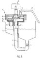
- Figure 5 shows schematically, the incorporation of such a valve control in a coffee machine of a type known per se and comprising a liquid tank 1 connected by a line 2 to a control valve to several channels 3.
- the heating means 4 forming the boiler of the device is constituted by a heating resistor of armored type in thermal relation with line 2 so as to be able to heat the water and ensure simultaneously its circulation.
- the heating resistor has a shape characteristic in L, and can be considered as a low boiler pressure, capable of generating a pressure in the system of less than 1 bar and preferably between 0.5 and 0.6 bars.
- the pipe 2 comprises a non-return valve 5.
- the resistance heater 4 therefore simultaneously assumes a pump function and a heating function.
- the control valve 3 is a valve with several channels capable of selectively controlling the water functions hot / steam, from a hot beverage machine, such as a coffee machine, fitted with a low pressure boiler.
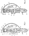
- this last comprises a main body 10 in the form of a hollow body of substantially oblong shape and axis of symmetry x-x '.
- the main body 10 is provided with an inlet 11 capable, by through a pipe, such as pipe 2 ( Figure 5), from communicate with the boiler of the hot beverage appliance, the occurrence of the armored resistor 4 for example.
- the main body 10 also has two outlet openings respectively hot water 12 and steam 13, located on either side of the inlet 11 and at a distance therefrom.
- the multi-way control valve 3 comprises also a dispensing finger 20 in the form of a rod comprising several sections of profiles and diameters suitable for allow according to the axial position of the rod in the main body 10, the selective passage of the fluid from the inlet 11 to one or other of the outlet ports 12, 13.
- the dispensing finger 20 is movably mounted in the main body 10 and is capable, through a control member to which it is connected, of relate through a circuit formed between the main body 10 and the external faces of the dispensing finger 20, the inlet orifice 11 with one or the other of the outlet orifices 12, 13.
- the portion of the circuit connecting the inlet 11 to the hot water outlet 12 present over its entire length a constant section, which is substantially equal to the section of the inlet 11.
- the hot water which has been heated by through the heating resistor 4 in the conduit 2 and which arrives in the control valve 3 through the inlet 11 is not subject to any restriction within the valve itself since the hot water flows through a portion of circuit whose section is substantially identical to that of the input section.
- the displacement of the dispensing finger 20 is obtained at using a movement combining a rotation of the finger around the axis x-x ', with an axial displacement along the same axis.
- Such displacement can be obtained by a set of controls associating a light 21 (FIG. 4) formed in the thickness of the envelope of the main body 10 to form a sliding ramp on the one hand, and a stud 22 secured to the finger distribution 20 and intended to be inserted into the light 21 to move in the latter on the other hand.
- the dispensing finger 20 thus forms a slide mounted movable axially by rotation.
- the control member for the movement of the dispensing finger 20 is advantageously formed by a button 25 secured to one end of the finger distribution 20.
- the body main 10 also has a recycling outlet 15 located between the inlet 11 and the hot water outlet 12 allowing, by through the dispensing finger 20, the passage of the liquid from the orifice inlet 11 to the reservoir 1 of the beverage machine.
- the distribution finger 20 has a series of O-rings 26 intended to ensure in combination with the specific shapes of the finger distribution 20, the sealing of the valve operation.
- the valve according to the invention also comprises a tube 27 for the outlet of steam extending the steam outlet orifice 13.
- the valve according to the invention is more particularly intended to be integrated in a substantially horizontal position on the beverage machine. It involves also an anti-siphoning system 30 mounted at the top of the valve, opposite the control button 25, said anti-siphoning system 30 being mounted in an upper chamber 31 formed in the main body 10 and therefore subject to the pressure prevailing in the valve 3.
- the anti-siphoning system 30 comprises a safety valve 32 mounted in the chamber 31 in the vicinity of the steam outlet orifice 13.
- the safety valve 32 has a receiving chamber 33 for a ball 34, and is surrounded by a flange 35.
- the safety valve 32 rests by the flange 35 against the upper end of the main body 10 and is resiliently movable mounted against at least one spring 36 interposed between the flange 35 and a closing cap 37. In the rest position, the valve 32 therefore prevents the venting of the valve due to the force exerted by spring 36.
- the safety valve 32 is consequently mounted resiliently movable against the spring 36 and is associated with the ball 34 itself mounted freely displaceable under the effect of the pressure prevailing in the main body 10 in the chamber 33 which is itself provided with a fluid exhaust orifice.
- the consumer brings in by rotation and translation, using the button control 25, the dispensing finger 20 in the selected position, at know the so-called hot water position, corresponding to Figure 1, the so-called position recycling, corresponding to FIG. 2, or the so-called steam position, corresponding to figure 3.
- hot water can pass directly from the inlet 11 to the outlet 12 following the circuit closed internal with constant section of the valve.
- the water arriving through the orifice inlet 11 is channeled to recycling outlet 15 and can thus return to tank 1.
- the steam can therefore pass from the inlet 11 to the outlet of steam 13.
- the anti-siphoning device 30 is inactive, since due to the internal pressure prevailing in the valve, the ball 34 closes the orifice of the chamber 33 preventing venting of the system.
- the elastic mounting of the anti-siphoning system 30 also makes it possible overpressure, venting the system through mounting elastic of the safety valve 32.
- the anti-siphon system 30 can be considered a dual function security system.
- the latter may consist of a deformable tongue 40 formed in the form of a U-shaped cut in a disc 41 produced for example in plastic material.
- the tongue 40 is deformable under the effect of the pressure prevailing in the main body 10, and, is threaded on a rib 42 coming from an annular piece 43 on which comes to rest said tongue 40.
- the invention finds its application in devices for preparing hot drinks.
Landscapes
- Engineering & Computer Science (AREA)
- Food Science & Technology (AREA)
- Apparatus For Making Beverages (AREA)
- Cookers (AREA)
Description
- Les figures 1, 2 et 3 montrent, selon des coupes transversales longitudinales, une vanne de commande à plusieurs voies conforme à l'invention et correspondant respectivement à une position de production d'eau chaude, à une position de recyclage, et à une position de production de vapeur.
- La figure 4 montre selon une vue en perspective éclatée, une variante de réalisation d'une vanne conforme à l'invention, dans laquelle le système anti-siphonnage est constitué d'une languette déformable.
- La figure 5 illustre une machine à café dans laquelle une vanne de commande conforme à l'invention peut être montée.
Claims (9)
- Vanne de commande (3) à plusieurs voies pour commander sélectivement les fonctions eau chaude / vapeur d'une machine à boisson chaude, telle qu'une machine à café; équipée d'une chaudière (4) basse pression, ladite vanne comprenant un corps principal (10) avec un orifice d'entrée (11) susceptible de communiquer avec la chaudière (4) et deux orifices de sortie (12,13), respectivement d'eau chaude et de vapeur, caractérisée en ce qu'elle comprend également un doigt de distribution (20), monté mobile dans le corps principal (10) et susceptible, par l'intermédiaire d'un organe de commande (25) auquel il est relié, de mettre en relation à travers un circuit formé entre le corps principal (10) et le doigt (20), l'orifice d'entrée (11) avec l'un ou l'autre des orifices de sortie (12,13), la portion de circuit reliant l'orifice d'entrée (11) à l'orifice de sortie eau chaude (12) présentant sur toute sa longueur une section constante sensiblement égale à celle de l'orifice d'entrée (11) et à l'orifice d'eau chaude (12).
- Vanne selon la revendication 1 caractérisée en ce que le corps principal (10) comporte une sortie de recyclage (15) permettant, par l'intermédiaire du doigt de distribution (20), le passage du liquide de l'orifice d'entrée (11) vers le réservoir (1) de la machine à boisson.
- Vanne selon l'une des revendications 1 ou 2, caractérisée en ce que le doigt de distribution (20) est un coulisseau monté mobile axialement par rotation dans le corps principal.
- Vanne selon l'une des revendications 1 à 3, caractérisée en ce que l'organe de commande (25) est un bouton solidaire d'une extrémité du doigt de distribution (20).
- Vanne selon l'une des revendications 1 à 4, caractérisée en ce qu'elle comporte un système anti-siphonnage (30).
- Vanne selon la revendication 5, caractérisée en ce que le système anti-siphonnage comprend une soupape de sécurité (32) montée dans le corps principal (10) au voisinage de l'orifice de sortie de vapeur (13), ladite soupape faisant également office de soupape de sécurité en cas de surpression.
- Vanne selon la revendication 6, caractérisée en ce que la soupape (32) est montée élastiquement mobile contre un ressort (36) pour assurer la sécurité en cas de surpression et est associée à une bille (34) montée librement déplaçable sous l'effet de la pression régnant dans le corps principal (10) dans une chambre (33) ménagée dans la soupape (32), laquelle est pourvue d'un orifice d'échappement.
- Vanne selon la revendication 6, caractérisée en ce que la soupape (32) est formée par une languette déformable (40) sous l'effet de la pression régnant dans le corps principal.
- Machine à boisson chaude en particulier machine à café, équipée d'une vanne conforme à l'une des revendications 1 à 8.
Applications Claiming Priority (3)
| Application Number | Priority Date | Filing Date | Title |
|---|---|---|---|
| FR9506796A FR2734882B1 (fr) | 1995-06-02 | 1995-06-02 | Vanne de commande a plusieurs voies pour machine a boisson chaude, en particulier machine a cafe, equipee d'une chaudiere basse pression |
| FR9506796 | 1995-06-02 | ||
| PCT/FR1996/000835 WO1996038078A1 (fr) | 1995-06-02 | 1996-06-03 | Vanne de commande a plusieurs voies pour machine a boisson chaude, en particulier machine a cafe, equipee d'une chaudiere basse pression |
Publications (2)
| Publication Number | Publication Date |
|---|---|
| EP0833582A1 EP0833582A1 (fr) | 1998-04-08 |
| EP0833582B1 true EP0833582B1 (fr) | 2000-06-07 |
Family
ID=9479766
Family Applications (1)
| Application Number | Title | Priority Date | Filing Date |
|---|---|---|---|
| EP96920892A Expired - Lifetime EP0833582B1 (fr) | 1995-06-02 | 1996-06-03 | Vanne de commande a plusieurs voies pour machine a boisson chaude, en particulier machine a cafe, equipee d'une chaudiere basse pression |
Country Status (5)
| Country | Link |
|---|---|
| EP (1) | EP0833582B1 (fr) |
| AU (1) | AU6228896A (fr) |
| DE (1) | DE69608802T2 (fr) |
| FR (1) | FR2734882B1 (fr) |
| WO (1) | WO1996038078A1 (fr) |
Families Citing this family (1)
| Publication number | Priority date | Publication date | Assignee | Title |
|---|---|---|---|---|
| DE102004062746A1 (de) * | 2004-12-27 | 2006-07-06 | BSH Bosch und Siemens Hausgeräte GmbH | Kaffeemaschine |
Family Cites Families (4)
| Publication number | Priority date | Publication date | Assignee | Title |
|---|---|---|---|---|
| FR1508901A (fr) * | 1966-02-09 | 1968-03-20 | ||
| EP0217211A3 (fr) * | 1985-09-23 | 1987-10-21 | ESSEGIELLE S.r.l | Machine à café |
| DE8704298U1 (de) * | 1986-03-24 | 1987-08-13 | Oficina de Investigacion Agrupada, S.A., Eibar, Guipzucoa | Wasserdurchgangsventil für Kaffeemaschinen |
| DE8717864U1 (de) * | 1987-09-16 | 1990-11-29 | Arthur Eugster AG, Romanshorn | Vorrichtung für die Zubereitung von Heißgetränken |
-
1995
- 1995-06-02 FR FR9506796A patent/FR2734882B1/fr not_active Expired - Fee Related
-
1996
- 1996-06-03 AU AU62288/96A patent/AU6228896A/en not_active Abandoned
- 1996-06-03 EP EP96920892A patent/EP0833582B1/fr not_active Expired - Lifetime
- 1996-06-03 DE DE69608802T patent/DE69608802T2/de not_active Expired - Fee Related
- 1996-06-03 WO PCT/FR1996/000835 patent/WO1996038078A1/fr not_active Ceased
Also Published As
| Publication number | Publication date |
|---|---|
| FR2734882A1 (fr) | 1996-12-06 |
| DE69608802D1 (de) | 2000-07-13 |
| EP0833582A1 (fr) | 1998-04-08 |
| AU6228896A (en) | 1996-12-18 |
| DE69608802T2 (de) | 2000-12-07 |
| FR2734882B1 (fr) | 1997-07-25 |
| WO1996038078A1 (fr) | 1996-12-05 |
Similar Documents
| Publication | Publication Date | Title |
|---|---|---|
| WO2017064438A1 (fr) | Vanne fluidique a hysteresis | |
| FR2751242A1 (fr) | Filtre a gazole pour moteur diesel et dispositif d'alimentation incluant un tel filtre | |
| FR3015613A1 (fr) | Vanne de commande pour un circuit de circulation de fluide, notamment pour vehicule automobile | |
| WO2018042050A1 (fr) | Cartouche thermostatique | |
| FR2895421A1 (fr) | Fer a repasser comprenant une vanne commandee par un element thermiquement deformable | |
| EP1794041B1 (fr) | Dispositif de rechauffage de l'eau des lave-vitres d'un vehicule automobile | |
| FR2791033A1 (fr) | Systeme de remplissage de recipients | |
| FR2610373A1 (fr) | Appareil de conditionnement d'un carburant liquide | |
| FR2805591A1 (fr) | Dispositif thermostatique a deux regimes de regulation commandes selectivement | |
| EP1155271B1 (fr) | Echangeur thermique a plaques, a vanne integree | |
| WO1996038078A1 (fr) | Vanne de commande a plusieurs voies pour machine a boisson chaude, en particulier machine a cafe, equipee d'une chaudiere basse pression | |
| EP0109467B1 (fr) | Robinet à fonctionnement semi-automatique permettant de délivrer un volume prédéterminé d'un fluide sous pression, notamment robinet de chasse | |
| FR2984448A1 (fr) | Detendeur de gaz a securite de surpression integree | |
| FR2504653A1 (fr) | Dispositif d'alimentation pour appareils mobiles de chauffage au gaz | |
| FR3054282A1 (fr) | Unite de melange et robinet mitigeur comprenant une telle unite de melange | |
| EP2126189B1 (fr) | Fer a repasser a vapeur comprenant un reservoir muni d'un dispositif de securite contre les surpressions | |
| EP1317575A2 (fr) | Fer a vapeur auto nettoyant | |
| FR2722244A1 (fr) | Dispositif de thermoregulation d'un moteur thermique | |
| EP3705621B1 (fr) | Fer à repasser comprenant un volet de remplissage équipé d'un joint d'étanchéité | |
| EP0516528B1 (fr) | Clapet de sécurité pour circuit de ventilation d'un réservoir de carburant de véhicule automobile | |
| FR3012482A1 (fr) | Chasse d'eau double flux | |
| FR2654178A1 (fr) | Soupape distributrice comportant une soupape de purge. | |
| EP0588162B1 (fr) | Fer à repasser à vapeur | |
| EP0924465B1 (fr) | Générateur d'eau chaude à commande eau | |
| CH665460A5 (fr) | Robinet pour bruleurs a gaz de cuisinieres. |
Legal Events
| Date | Code | Title | Description |
|---|---|---|---|
| PUAI | Public reference made under article 153(3) epc to a published international application that has entered the european phase |
Free format text: ORIGINAL CODE: 0009012 |
|
| 17P | Request for examination filed |
Effective date: 19971217 |
|
| AK | Designated contracting states |
Kind code of ref document: A1 Designated state(s): DE IT |
|
| 17Q | First examination report despatched |
Effective date: 19981023 |
|
| GRAG | Despatch of communication of intention to grant |
Free format text: ORIGINAL CODE: EPIDOS AGRA |
|
| GRAG | Despatch of communication of intention to grant |
Free format text: ORIGINAL CODE: EPIDOS AGRA |
|
| GRAH | Despatch of communication of intention to grant a patent |
Free format text: ORIGINAL CODE: EPIDOS IGRA |
|
| GRAH | Despatch of communication of intention to grant a patent |
Free format text: ORIGINAL CODE: EPIDOS IGRA |
|
| GRAA | (expected) grant |
Free format text: ORIGINAL CODE: 0009210 |
|
| AK | Designated contracting states |
Kind code of ref document: B1 Designated state(s): DE IT |
|
| REF | Corresponds to: |
Ref document number: 69608802 Country of ref document: DE Date of ref document: 20000713 |
|
| ITF | It: translation for a ep patent filed | ||
| PLBE | No opposition filed within time limit |
Free format text: ORIGINAL CODE: 0009261 |
|
| STAA | Information on the status of an ep patent application or granted ep patent |
Free format text: STATUS: NO OPPOSITION FILED WITHIN TIME LIMIT |
|
| 26N | No opposition filed | ||
| PGFP | Annual fee paid to national office [announced via postgrant information from national office to epo] |
Ref country code: DE Payment date: 20090717 Year of fee payment: 14 |
|
| PGFP | Annual fee paid to national office [announced via postgrant information from national office to epo] |
Ref country code: IT Payment date: 20090630 Year of fee payment: 14 |
|
| PG25 | Lapsed in a contracting state [announced via postgrant information from national office to epo] |
Ref country code: IT Free format text: LAPSE BECAUSE OF NON-PAYMENT OF DUE FEES Effective date: 20100603 |
|
| PG25 | Lapsed in a contracting state [announced via postgrant information from national office to epo] |
Ref country code: DE Free format text: LAPSE BECAUSE OF NON-PAYMENT OF DUE FEES Effective date: 20110101 |