EP0833333A1 - Disk package - Google Patents
Disk package Download PDFInfo
- Publication number
- EP0833333A1 EP0833333A1 EP97307028A EP97307028A EP0833333A1 EP 0833333 A1 EP0833333 A1 EP 0833333A1 EP 97307028 A EP97307028 A EP 97307028A EP 97307028 A EP97307028 A EP 97307028A EP 0833333 A1 EP0833333 A1 EP 0833333A1
- Authority
- EP
- European Patent Office
- Prior art keywords
- disk
- tray
- trays
- lock
- case
- Prior art date
- Legal status (The legal status is an assumption and is not a legal conclusion. Google has not performed a legal analysis and makes no representation as to the accuracy of the status listed.)
- Granted
Links
- 230000007246 mechanism Effects 0.000 claims abstract description 59
- 238000001514 detection method Methods 0.000 description 30
- 230000003287 optical effect Effects 0.000 description 12
- 239000003086 colorant Substances 0.000 description 6
- 230000000994 depressogenic effect Effects 0.000 description 6
- 239000011295 pitch Substances 0.000 description 3
- 238000010586 diagram Methods 0.000 description 2
- 230000009191 jumping Effects 0.000 description 2
- 229920003002 synthetic resin Polymers 0.000 description 2
- 239000000057 synthetic resin Substances 0.000 description 2
- 230000002411 adverse Effects 0.000 description 1
- 230000005540 biological transmission Effects 0.000 description 1
- 230000010485 coping Effects 0.000 description 1
- 230000006870 function Effects 0.000 description 1
- 230000037431 insertion Effects 0.000 description 1
- 238000003780 insertion Methods 0.000 description 1
- 230000002093 peripheral effect Effects 0.000 description 1
- 230000035939 shock Effects 0.000 description 1
Images


Classifications
-
- G—PHYSICS
- G11—INFORMATION STORAGE
- G11B—INFORMATION STORAGE BASED ON RELATIVE MOVEMENT BETWEEN RECORD CARRIER AND TRANSDUCER
- G11B17/00—Guiding record carriers not specifically of filamentary or web form, or of supports therefor
-
- G—PHYSICS
- G11—INFORMATION STORAGE
- G11B—INFORMATION STORAGE BASED ON RELATIVE MOVEMENT BETWEEN RECORD CARRIER AND TRANSDUCER
- G11B23/00—Record carriers not specific to the method of recording or reproducing; Accessories, e.g. containers, specially adapted for co-operation with the recording or reproducing apparatus ; Intermediate mediums; Apparatus or processes specially adapted for their manufacture
- G11B23/02—Containers; Storing means both adapted to cooperate with the recording or reproducing means
- G11B23/03—Containers for flat record carriers
- G11B23/032—Containers for flat record carriers for rigid discs
- G11B23/0323—Containers for flat record carriers for rigid discs for disc-packs
-
- G—PHYSICS
- G11—INFORMATION STORAGE
- G11B—INFORMATION STORAGE BASED ON RELATIVE MOVEMENT BETWEEN RECORD CARRIER AND TRANSDUCER
- G11B23/00—Record carriers not specific to the method of recording or reproducing; Accessories, e.g. containers, specially adapted for co-operation with the recording or reproducing apparatus ; Intermediate mediums; Apparatus or processes specially adapted for their manufacture
- G11B23/02—Containers; Storing means both adapted to cooperate with the recording or reproducing means
- G11B23/03—Containers for flat record carriers
- G11B23/0301—Details
- G11B23/031—Indicating means, e.g. sticker, bar code
-
- G—PHYSICS
- G11—INFORMATION STORAGE
- G11B—INFORMATION STORAGE BASED ON RELATIVE MOVEMENT BETWEEN RECORD CARRIER AND TRANSDUCER
- G11B17/00—Guiding record carriers not specifically of filamentary or web form, or of supports therefor
- G11B17/22—Guiding record carriers not specifically of filamentary or web form, or of supports therefor from random access magazine of disc records
- G11B17/30—Guiding record carriers not specifically of filamentary or web form, or of supports therefor from random access magazine of disc records wherein the playing unit is moved according to the location of the selected record
Definitions
- a combination of data of a disk in one package a combination of an operating system for computer and application software of a plurality of types, a combination of music data and video data, a combination of various game software, a combination of various data corresponding to encyclopedia data, or the like are recorded. More preferably, a read-only disk (ROM disk) and a recordable disk (RAM disk) are loaded in the same package at once. In the package in which both the ROM and the RAM are loaded at once can be used as a personal-library type storage device which can use both available software and personally edited data or software.
- ROM disk read-only disk
- RAM disk recordable disk
- the second lock mechanism is preferably exposed in a small hole of the case to prevent a lock releasing operation from being easily performed. In this manner, when the disk package is removed from the disk device, the tray which is inhibited from being removed is not erroneously drawn.
- the tray T is drawn to the position indicated by the chain line in FIG. 3, when the disk D placed on the tray T is slightly lifted from the tray T and rotatively driven, the disk D is not brought into contact with the tray T located above the disk D. More specifically, in this case, the tray T is drawn to a position where the central hole of the disk D comes outside the case 1, and the disk D on the tray T can be rotatively driven while the disk D is partially located in the case 1.
- the disk drive means E is mounted on the selection moving base 10.
- the disk drive means E has a turn table 11 for holding the central hole portion of the disk D on a drive base E1 and a spindle motor 12 for rotatively driving the turn table 11.
- a guide shaft 14 extending in the radial direction of the disk D and a drive screw shaft 15 extending parallel to the guide shaft 14 are arranged, a bearing portion 13b of an optical head 13 is slidably supported by the guide shaft 14, and a female screw portion 13c of the optical head 13 is meshed with the drive screw shaft 15.
- the optical head 13 can perform a reading operation for disks D such as a CD and a DVD whose types are different from each other.
- disks D such as a CD and a DVD whose types are different from each other.
- the objective lens 13a two lenses having different focuses are arranged in such a manner that the lenses can be switched.
- the drive base E1 After the tray T is drawn, the drive base E1 returns to the horizontal posture, and the case 1 is fitted in the central hole of the disk D. At this time, the disk D is slightly lifted from the tray T, and the disk D is clamped by the turn table 11 and a clamp member (not shown) to be rotatively driven.
- the recessed portion 18a of the drawing lever 18 moves to a position where the recessed portion 18a can be engaged with the hook T7 of the second tray T from the bottom.
- the drawing lever 18 moves in the left direction in FIG. 1, the selected tray T is drawn into the disk drive means E by the drawing lever 18.
- a discrimination means for discriminating the types of the disks from each other is arranged on the disk package P side.
- the trays T classified by different colors can be visually recognized from the opening 1a side of the case 1.
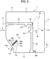
- a window 1g is opened in the surface of the case 1 on the right side in FIG. 3, i.e., the front plate 1e which can be viewed from the front of the disk device when the disk package P is disposed in the disk device, and a transparent panel is fitted in the window 1g. Therefore, in a state wherein the disk package P is disposed in the disk device, when the window 1g formed in the front plate 1e is viewed from the front, the colors of the trays T in the case 1 can be visually checked.
- a discrimination means 20 for indicating the types of the disks stored in the case 1 is arranged on the bottom surface 1f of the case 1 of the disk package P.
- the 3-bit discrimination information it can be recognized on the device body side whether a disk D stored on a specific stage in the disk package P is a RAM disk or a ROM disk. A combination among the types of five disks can also be recognized on the device body side. When the discrimination holes are increased in number, larger pieces of discrimination information can be obtained on the device body side.
- a storage element such as an IC card may be buried in the case 1 as the discrimination means 20, and the IC card or the like may be accessed by a contact point on the housing A side.
- information held by the case 1 increases in amount, not only information about the types of disks stored in the case 1 but also the contents of information recorded on the disks, other TOC data, or information similar thereto can also be given to the device body.
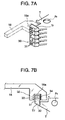
- the discrimination means 30 is arranged at the portion of the hooks T7 of the respective trays T.
- 2-bit discrimination holes 31 are formed in the hook T7 of each tray T.
- a detection means 32 on the device body side is arranged on the drawing lever 18 mounted on the selection moving base 10.
- the detection means 32 is constituted by two photoreflectors 33 arranged on one of the inner surfaces which interpose the recessed portion 18a therebetween, and a reflective sheet (reflective surface) 34 arranged on the other inner surface.
- the discrimination hole 31 is opened or closed to give discrimination information. When the discrimination hole 31 is opened, detection light emitted from the photoreflector 33 is transmitted through the discrimination hole 31, reflected from the reflective sheet 34, and detected by the photoreflector 33.
- information "1" and "0” can be given by checking whether the discrimination hole 31 is opened or not.
- one tray T has 2-bit information. According to the 2-bit information, discrimination among disks placed on the trays T, e.g., discrimination between a ROM disk and a RAM disk placed on the trays T, and discrimination among the recording schemes of the disks can be performed.
- the discrimination means 30 arranged on each tray T is not limited to a means for detecting the presence/absence of the discrimination hole 31, and the discrimination means 30 having the following arrangement may be used.
- the attaching portion of the reflective sheet is formed at any position of the tray T, a photoreflector which can face the reflective sheet is arranged on the selection moving base 10, and discrimination information of the disks are given by checking whether the reflective sheet is attached to the tray T.
- Discrimination information may also be given by checking whether the presence/absence of a discrimination projection formed on the tray T is detected by a switch arranged on the selection moving base 10.
- any one of the discrimination means 20 arranged in the case 1 shown in FIG. 5 and the discrimination means 30 arranged on each tray T may be arranged, or both of them may be used.
- the discrimination means 20 arranged in the case 1 and/or the discrimination means 30 arranged on the trays T, and discrimination information of the disks obtained such that reading TOC data of the disks D is read by the optical head 13 or the track pitches of the disks are detected by the optical head 13 can be also be used at once.
- discrimination information of the disks from the case and/or the trays and discrimination information obtained by directly accessing the disks by the optical head 13 are used at once, the precision of recognition of the disk types can be improved. For example, the following accident can be prevented. That is, a ROM disk is erroneously identified as a RAM disk, and a recording laser power is given to the recording surface of the ROM disk to break recording information.
- a light protect portion Pr is formed on the inner side of the hook T7 of the tray T.
- This light protect portion Pr is formed on only a tray on which a RAM disk is placed, and this tray is partially thinned.
- a detection portion opposes the light protect portion Pr.
- This detection portion is constituted by a light-emitting element opposing one side of the light protect portion Pr and a light-receiving element opposing the other side.
- a first lock mechanism L1 for preventing all the trays T from unexpectedly projecting in a state wherein the disk package P is removed from the disk device, and a second lock mechanism L2 for preventing only a tray T on which a RAM disk is placed in a state wherein a locking operation of the first lock mechanism L1 is released are arranged.
- the RAM disk can be prevented from being unexpectedly drawn to prevent the recording surface of the disk from being stained and damaged in a state wherein the disk package P is removed from the disk device.
- FIG. 8 is a plan sectional view of a part of the disk package P showing the first lock mechanism L1 in FIG. 1, and FIG. 9 is a longitudinal sectional view showing the same part as that in FIG. 8.
- a lock shaft 41 is arranged in the case 1 of the disk package P.
- a small-diameter shaft 41a integrally formed on the lower end of the lock shaft 41 is inserted through the bottom surface 1f of the case 1, and a small-diameter shaft 41b integrally formed on the upper end of the lock shaft 41 is inserted into a recessed portion 1i formed on an upper surface 1h of the case 1.
- the lock shaft 41 can be freely pivoted and can be slid downwards from the position shown in FIG. 9 in the Z direction.
- a torsion coil spring 43 is arranged on the outer periphery of the small-diameter shaft 41a on the low end side.
- the elastic force of the torsion coil spring 43 urges the lock shaft 41 counterclockwise in the plan sectional view of FIG. 8, and the torsion coil spring 43 urges the lock shaft 41 upwards in FIG. 9.
- the small-diameter shaft 41b arranged on the upper end of the lock shaft 41 projects upwards in the recessed portion 1i of the upper surface 1h of the case 1, and the small-diameter shaft 41b is designed to function as a lock releasing operation portion.
- the lock shaft 41 has five lock pawls (lock portions) 42 which are integrally formed at predetermined intervals.
- engagement projections T8 corresponding to the lock pawls 42 are integrally formed on all the trays T stored in the case 1.
- a pressed projection 44 projecting to the inside of the case 1 is integrally formed on the lock shaft 41.
- a lock releasing lever 45 serving as a lock releasing member for releasing a locking operation of the first lock mechanism L1 is arranged on the inner side of the bottom surface 1f in the case 1.
- the lock releasing lever 45 is pivotally supported by a support pin 46 formed on the inner surface of the bottom surface 1f, and the lock releasing lever 45 is urged by a spring member (not shown) clockwise in FIGS. 3 and 8.
- a pressing portion 48 is formed on the end portion of the lock releasing lever 45, and the pressing portion 48 opposes the pressed projection 44 formed on the lock shaft 41.
- a projection 47 is integrally formed on an intermediate portion of the lock releasing lever 45. As shown in FIG. 5, the projection 47 slightly projects in the end 3b of both the guide groove 3a extending in the X direction and the guide groove 3c extending in the Y direction, which guide grooves are formed in the bottom surface 1f of the case 1.
- FIG. 10 is a partially exploded perspective view showing the structure of the second lock mechanism L2
- FIGS. 11A and 11B are enlarged plan views showing relationships between the second lock mechanism L2 and a tray on which a RAM disk is placed in different states.
- the second lock mechanism L2 locks only a tray T on which a RAM disk is placed.
- the tray on which the RAM disk is placed is represented by symbol Ta
- a tray on which a ROM disk is placed is represented by symbol To.
- a projection portion 51 is formed on the side edge portion of a tray Ta for RAM disk on the right side with respect to the X direction.
- a hole 54 is opened in the inner side of the projection portion 51, and the projection portion 51 is joined to the body portion of the tray Ta through a thin portion 52 which can be deformed and a thin portion 53 which can be separated.
- the end face of the projection portion 51 on the X-direction side serves as an engagement surface 51a.
- the projection portion 51 and the engagement surface 51a constitute an engagement portion which is engaged with the second lock mechanism L2.
- the projection portion 51 is not formed, and a side edge portion 55 on the right side of the tray To is linearly formed.
- a lock member 56 is slidably supported in the Z directions (vertical directions) between the bottom surface 1f and the upper surface 1h of the case 1 of the disk package P and in the thickness of the right plate 1c. As shown in FIG. 10, the upper end of the lock member 56 is pressed downwards by a urging spring 57, and the lock member 56 is moved downwards in the Z direction by the elastic force of the urging spring 57.
- Lock portions 56a and unlock portions 56b are alternately formed in the lock member 56 in the Z directions.
- the unlock portions 56b are formed such that grooves are intermittently formed.
- the alignment pitch of the lock portions 56a in the Z directions is equal to the alignment pitch of the trays T.
- the lock member 56 When the disk package P is removed from the disk device, the lock member 56 is urged downwards in FIG. 10 to be moved. For this reason, the lock portion 56a opposes the engagement surface 51a of the tray Ta for RAM disk in the X direction in such a manner that the lock portion 56a and the engagement surface 51a are engaged with each other.
- a bottom surface 56c (see FIG. 5) of the lock member 56 appearing in the bottom surface 1f of the case 1 is pressed by a lock releasing member 58 (see FIG. 10) arranged in the housing A, and the lock member 56 slightly moves upward in the Z axis.
- the unlock portion 56b opposes the front of the engagement surface 51a of the tray Ta for RAM disk.
- the lock releasing member 58 is brought into contact with the bottom surface 56c of the lock member 56 having a small area as shown in FIG. 5 to press the bottom surface 56c into the case 1, and the lock releasing member 58 is urged by a leaf spring 58a in the pressing direction, or the lock releasing member 58 is driven in the pressing direction by mechanical moving force.
- the lock portion 56a of the lock member 56 is engaged with the front of the engagement surface 51a of the tray Ta on which a RAM disk is placed, so that the tray Ta is locked to be prevented from being removed.
- the tray To is not locked by the second lock mechanism L2.
- the small-diameter shaft 41b projecting from the upper surface 1h of the case 1, and the small-diameter shaft 41b can be pressed with a finger.
- the lock member 56 of the second lock mechanism L2 has a small section, and the bottom surface 56c (see FIG. 5) of the lock member 56 exposed from a small hole 1k formed in the bottom surface 1f of the case 1 is very small. Therefore, when the disk package P is removed from the disk device, the bottom surface 56c cannot be easily pressed with a finger, so that a locking operation of the second lock mechanism L2 cannot be easily released.
- a plurality of slits 1j are opened in the right plate 1c of the disk package P, and the projection portion 51 of the tray Ta on which the RAM disk is placed is exposed in the slits 1j.
- the tip of a tool such as a minus screw driver is inserted into the slit 1j to press the projection portion 51 of the side edge portion of the tray Ta.
- the thin portion 53 is separated, and the thin portion 52 is deformed, so that the projection portion 51 is inserted into the hole 54.
- a front inner surface 54a of the hole 54 in the X direction serves an inclined engagement surface having the right side (in FIGS. 11A and 11B) facing backwards (anti-X direction), and the projection portion 51 deformed in the hole 54 is engaged with the front inner surface 54a at (i) portion. Therefore, the projection portion 51 is reliably buried in the hole 54 and does not project in the side direction again.
- the tray Ta having the projection portion 51 which is once depressed cannot be used as the tray Ta for RAM disk after the projection portion 51 is depressed.
- the tray has a ROM disk placed thereon to be used as only a tray for ROM disk.
- the type (type depending on whether a disk placed on a tray is a RAM disk or not) of a tray can also be detected.
- a reflective sheet 61 is attached to a side surface of the projection portion 51, and the disk package P is disposed in the housing A, photoreflectors 62 opposing the slits 1j formed in the right plate 1c of the case 1 are arranged as detection means.
- the tray Ta on which the RAM disk is placed is located at the position.
- the arrangement angle of the photoreflector 62 may be set in such a manner that the photoreflector 62 cannot receive light reflected from the reflective sheet 61 on the surface of the projection portion 51.
- the disk package can be used as a large-capacity storage media, and the disk package in which a RAM disk and a ROM disk are used at once can be used as a storage media for a personal library. Since all trays are locked in a state wherein the disk package is removed from the disk device, the trays and disks do not erroneously fall off the case. In addition, in a disk package removed from a disk device, when only a predetermined disk is inhibited from being removed, a basic disk can be prevented from being erroneously exchanged, or a RAM disk can be prevented from being removed and stained.
Abstract

Description
Claims (3)
- A disk package comprising a case which can be disposed in a device body, a plurality of trays on which a plurality of disks of at least two different types are respectively placed and which are stored in said case in such a manner that said trays can be drawn out of said case, an engagement portion formed on only a tray, on which a predetermined disk is placed, of said plurality of trays, a first lock mechanism for locking all said trays in said case, a lock releasing operation portion which can release a locking operation of said first lock mechanism, and a second lock mechanism, engaged with said engagement portion, which locks only said tray on which the predetermined disk is placed and does not lock other trays, characterized in that said engagement portion can be deformed by an operation performed out of said case in such a manner that said engagement portion is not engaged with said second lock mechanism, and said first lock mechanism and said second lock mechanism perform a lock releasing operation when said first and second lock mechanisms are disposed in said device body.
- A disk package according to claim 1, wherein a recordable disk is placed on a tray on which said engagement portion is formed, and a read-only disk is placed on a tray on which said engagement portion is not formed.
- A disk package according to claim 1 or 2 wherein discrimination means which can be detected from the inside of said device body is arranged on said engagement portion.
Applications Claiming Priority (3)
| Application Number | Priority Date | Filing Date | Title |
|---|---|---|---|
| JP25289096A JP3264839B2 (en) | 1996-09-25 | 1996-09-25 | Disk package |
| JP252890/96 | 1996-09-25 | ||
| JP25289096 | 1996-09-25 |
Publications (2)
| Publication Number | Publication Date |
|---|---|
| EP0833333A1 true EP0833333A1 (en) | 1998-04-01 |
| EP0833333B1 EP0833333B1 (en) | 2001-05-30 |
Family
ID=17243595
Family Applications (1)
| Application Number | Title | Priority Date | Filing Date |
|---|---|---|---|
| EP97307028A Expired - Lifetime EP0833333B1 (en) | 1996-09-25 | 1997-09-10 | Disk package |
Country Status (6)
| Country | Link |
|---|---|
| US (1) | US5959949A (en) |
| EP (1) | EP0833333B1 (en) |
| JP (1) | JP3264839B2 (en) |
| KR (1) | KR100245486B1 (en) |
| DE (1) | DE69705006T2 (en) |
| TW (1) | TW338827B (en) |
Families Citing this family (4)
| Publication number | Priority date | Publication date | Assignee | Title |
|---|---|---|---|---|
| JP3502766B2 (en) * | 1998-06-03 | 2004-03-02 | パイオニア株式会社 | Disc playback device |
| JP3667140B2 (en) * | 1999-03-04 | 2005-07-06 | パイオニア株式会社 | Disc changer device |
| TWI272579B (en) * | 2004-12-17 | 2007-02-01 | Lite On It Corp | Disk changer and tray locking apparatus thereof |
| JP4758810B2 (en) * | 2006-04-24 | 2011-08-31 | 嘉作 鎌田 | Tightening fixture |
Citations (4)
| Publication number | Priority date | Publication date | Assignee | Title |
|---|---|---|---|---|
| EP0168107A2 (en) * | 1984-07-11 | 1986-01-15 | Koninklijke Philips Electronics N.V. | Magazine for a plurality of disc-shaped information carriers contained in holders and combination of a disc-player with such a magazine |
| US4800554A (en) * | 1986-10-01 | 1989-01-24 | Victor Company Of Japan, Limited | Disk magazine |
| EP0709840A2 (en) * | 1994-10-25 | 1996-05-01 | Sony Electronics Inc. | Latching cartridge magazines within cartridge storage devices |
| EP0712125A2 (en) * | 1994-11-14 | 1996-05-15 | International Business Machines Corporation | Cassette magazine for automated storage system |
Family Cites Families (7)
| Publication number | Priority date | Publication date | Assignee | Title |
|---|---|---|---|---|
| JPH0787002B2 (en) * | 1990-02-09 | 1995-09-20 | パイオニア株式会社 | Multiple disc storage player |
| US5136563A (en) * | 1990-02-16 | 1992-08-04 | Pioneer Electronic Corporation | Magazine holder in a CD player |
| US5481512A (en) * | 1992-06-30 | 1996-01-02 | Victor Company Of Japan, Ltd. | Separable magazine for accommodating discs and a disc player |
| KR0175335B1 (en) * | 1992-08-28 | 1999-04-15 | 구쯔사와 겐다로오 | Vibration resistant disc selectable player |
| JP3386850B2 (en) * | 1993-06-30 | 2003-03-17 | クラリオン株式会社 | Disk magazine |
| JP2956511B2 (en) * | 1995-02-08 | 1999-10-04 | 松下電器産業株式会社 | Automatic media exchange device and its magazine |
| US5638347A (en) * | 1995-06-06 | 1997-06-10 | International Business Machines Corporation | Disk cartridge storage system |
-
1996
- 1996-09-25 JP JP25289096A patent/JP3264839B2/en not_active Expired - Fee Related
-
1997
- 1997-09-08 TW TW086112964A patent/TW338827B/en active
- 1997-09-10 EP EP97307028A patent/EP0833333B1/en not_active Expired - Lifetime
- 1997-09-10 DE DE69705006T patent/DE69705006T2/en not_active Expired - Fee Related
- 1997-09-17 US US08/932,629 patent/US5959949A/en not_active Expired - Fee Related
- 1997-09-25 KR KR1019970048886A patent/KR100245486B1/en not_active IP Right Cessation
Patent Citations (4)
| Publication number | Priority date | Publication date | Assignee | Title |
|---|---|---|---|---|
| EP0168107A2 (en) * | 1984-07-11 | 1986-01-15 | Koninklijke Philips Electronics N.V. | Magazine for a plurality of disc-shaped information carriers contained in holders and combination of a disc-player with such a magazine |
| US4800554A (en) * | 1986-10-01 | 1989-01-24 | Victor Company Of Japan, Limited | Disk magazine |
| EP0709840A2 (en) * | 1994-10-25 | 1996-05-01 | Sony Electronics Inc. | Latching cartridge magazines within cartridge storage devices |
| EP0712125A2 (en) * | 1994-11-14 | 1996-05-15 | International Business Machines Corporation | Cassette magazine for automated storage system |
Also Published As
| Publication number | Publication date |
|---|---|
| TW338827B (en) | 1998-08-21 |
| DE69705006T2 (en) | 2001-09-13 |
| JP3264839B2 (en) | 2002-03-11 |
| KR100245486B1 (en) | 2000-02-15 |
| US5959949A (en) | 1999-09-28 |
| DE69705006D1 (en) | 2001-07-05 |
| EP0833333B1 (en) | 2001-05-30 |
| KR19980024983A (en) | 1998-07-06 |
| JPH10106200A (en) | 1998-04-24 |
Similar Documents
| Publication | Publication Date | Title |
|---|---|---|
| US6407982B1 (en) | Disk tray, disk storing apparatus and disk drive | |
| US5886961A (en) | Optical disk device capable of accessing a plural different types of optical disks | |
| KR100279086B1 (en) | Disk package | |
| JP3308455B2 (en) | Disk unit | |
| EP0872836B1 (en) | Optical disk discriminating method | |
| EP0833331B1 (en) | Disk package | |
| EP0833326B1 (en) | Disk package | |
| EP0833333B1 (en) | Disk package | |
| KR100269991B1 (en) | Recording medium identifying device | |
| JP3791531B2 (en) | Disc recording and / or playback device |
Legal Events
| Date | Code | Title | Description |
|---|---|---|---|
| PUAI | Public reference made under article 153(3) epc to a published international application that has entered the european phase |
Free format text: ORIGINAL CODE: 0009012 |
|
| 17P | Request for examination filed |
Effective date: 19980129 |
|
| AK | Designated contracting states |
Kind code of ref document: A1 Designated state(s): DE FR GB NL |
|
| AKX | Designation fees paid |
Free format text: DE FR GB NL |
|
| RBV | Designated contracting states (corrected) |
Designated state(s): DE FR GB NL |
|
| 17Q | First examination report despatched |
Effective date: 19990325 |
|
| GRAG | Despatch of communication of intention to grant |
Free format text: ORIGINAL CODE: EPIDOS AGRA |
|
| GRAG | Despatch of communication of intention to grant |
Free format text: ORIGINAL CODE: EPIDOS AGRA |
|
| GRAH | Despatch of communication of intention to grant a patent |
Free format text: ORIGINAL CODE: EPIDOS IGRA |
|
| GRAH | Despatch of communication of intention to grant a patent |
Free format text: ORIGINAL CODE: EPIDOS IGRA |
|
| GRAA | (expected) grant |
Free format text: ORIGINAL CODE: 0009210 |
|
| AK | Designated contracting states |
Kind code of ref document: B1 Designated state(s): DE FR GB NL |
|
| REF | Corresponds to: |
Ref document number: 69705006 Country of ref document: DE Date of ref document: 20010705 |
|
| ET | Fr: translation filed | ||
| REG | Reference to a national code |
Ref country code: GB Ref legal event code: IF02 |
|
| PLBE | No opposition filed within time limit |
Free format text: ORIGINAL CODE: 0009261 |
|
| STAA | Information on the status of an ep patent application or granted ep patent |
Free format text: STATUS: NO OPPOSITION FILED WITHIN TIME LIMIT |
|
| 26N | No opposition filed | ||
| PGFP | Annual fee paid to national office [announced via postgrant information from national office to epo] |
Ref country code: GB Payment date: 20040817 Year of fee payment: 8 |
|
| PGFP | Annual fee paid to national office [announced via postgrant information from national office to epo] |
Ref country code: FR Payment date: 20040921 Year of fee payment: 8 |
|
| PGFP | Annual fee paid to national office [announced via postgrant information from national office to epo] |
Ref country code: NL Payment date: 20040923 Year of fee payment: 8 |
|
| PGFP | Annual fee paid to national office [announced via postgrant information from national office to epo] |
Ref country code: DE Payment date: 20041123 Year of fee payment: 8 |
|
| PG25 | Lapsed in a contracting state [announced via postgrant information from national office to epo] |
Ref country code: GB Free format text: LAPSE BECAUSE OF NON-PAYMENT OF DUE FEES Effective date: 20050910 |
|
| PG25 | Lapsed in a contracting state [announced via postgrant information from national office to epo] |
Ref country code: NL Free format text: LAPSE BECAUSE OF NON-PAYMENT OF DUE FEES Effective date: 20060401 Ref country code: DE Free format text: LAPSE BECAUSE OF NON-PAYMENT OF DUE FEES Effective date: 20060401 |
|
| GBPC | Gb: european patent ceased through non-payment of renewal fee |
Effective date: 20050910 |
|
| PG25 | Lapsed in a contracting state [announced via postgrant information from national office to epo] |
Ref country code: FR Free format text: LAPSE BECAUSE OF NON-PAYMENT OF DUE FEES Effective date: 20060531 |
|
| NLV4 | Nl: lapsed or anulled due to non-payment of the annual fee |
Effective date: 20060401 |
|
| REG | Reference to a national code |
Ref country code: FR Ref legal event code: ST Effective date: 20060531 |