EP0872836B1 - Optical disk discriminating method - Google Patents
Optical disk discriminating method Download PDFInfo
- Publication number
- EP0872836B1 EP0872836B1 EP98302431A EP98302431A EP0872836B1 EP 0872836 B1 EP0872836 B1 EP 0872836B1 EP 98302431 A EP98302431 A EP 98302431A EP 98302431 A EP98302431 A EP 98302431A EP 0872836 B1 EP0872836 B1 EP 0872836B1
- Authority
- EP
- European Patent Office
- Prior art keywords
- disk
- magazine
- disks
- light
- tray
- Prior art date
- Legal status (The legal status is an assumption and is not a legal conclusion. Google has not performed a legal analysis and makes no representation as to the accuracy of the status listed.)
- Expired - Lifetime
Links
- 238000000034 method Methods 0.000 title claims description 13
- 230000003287 optical effect Effects 0.000 title description 18
- 238000001514 detection method Methods 0.000 claims description 33
- 239000000758 substrate Substances 0.000 claims description 16
- 230000007246 mechanism Effects 0.000 description 13
- 230000004907 flux Effects 0.000 description 3
- 230000002411 adverse Effects 0.000 description 2
- 238000011068 loading method Methods 0.000 description 2
- 230000002093 peripheral effect Effects 0.000 description 1
- 230000008569 process Effects 0.000 description 1
- 238000003672 processing method Methods 0.000 description 1
- 238000002310 reflectometry Methods 0.000 description 1
- 230000004044 response Effects 0.000 description 1
- 229920003002 synthetic resin Polymers 0.000 description 1
- 239000000057 synthetic resin Substances 0.000 description 1
- 230000001131 transforming effect Effects 0.000 description 1
Images


Classifications
-
- G—PHYSICS
- G11—INFORMATION STORAGE
- G11B—INFORMATION STORAGE BASED ON RELATIVE MOVEMENT BETWEEN RECORD CARRIER AND TRANSDUCER
- G11B27/00—Editing; Indexing; Addressing; Timing or synchronising; Monitoring; Measuring tape travel
- G11B27/002—Programmed access in sequence to a plurality of record carriers or indexed parts, e.g. tracks, thereof, e.g. for editing
-
- G—PHYSICS
- G11—INFORMATION STORAGE
- G11B—INFORMATION STORAGE BASED ON RELATIVE MOVEMENT BETWEEN RECORD CARRIER AND TRANSDUCER
- G11B19/00—Driving, starting, stopping record carriers not specifically of filamentary or web form, or of supports therefor; Control thereof; Control of operating function ; Driving both disc and head
- G11B19/02—Control of operating function, e.g. switching from recording to reproducing
- G11B19/12—Control of operating function, e.g. switching from recording to reproducing by sensing distinguishing features of or on records, e.g. diameter end mark
-
- G—PHYSICS
- G11—INFORMATION STORAGE
- G11B—INFORMATION STORAGE BASED ON RELATIVE MOVEMENT BETWEEN RECORD CARRIER AND TRANSDUCER
- G11B27/00—Editing; Indexing; Addressing; Timing or synchronising; Monitoring; Measuring tape travel
- G11B27/10—Indexing; Addressing; Timing or synchronising; Measuring tape travel
- G11B27/11—Indexing; Addressing; Timing or synchronising; Measuring tape travel by using information not detectable on the record carrier
-
- G—PHYSICS
- G11—INFORMATION STORAGE
- G11B—INFORMATION STORAGE BASED ON RELATIVE MOVEMENT BETWEEN RECORD CARRIER AND TRANSDUCER
- G11B2220/00—Record carriers by type
- G11B2220/20—Disc-shaped record carriers
- G11B2220/21—Disc-shaped record carriers characterised in that the disc is of read-only, rewritable, or recordable type
- G11B2220/215—Recordable discs
- G11B2220/216—Rewritable discs
-
- G—PHYSICS
- G11—INFORMATION STORAGE
- G11B—INFORMATION STORAGE BASED ON RELATIVE MOVEMENT BETWEEN RECORD CARRIER AND TRANSDUCER
- G11B2220/00—Record carriers by type
- G11B2220/20—Disc-shaped record carriers
- G11B2220/21—Disc-shaped record carriers characterised in that the disc is of read-only, rewritable, or recordable type
- G11B2220/215—Recordable discs
- G11B2220/218—Write-once discs
-
- G—PHYSICS
- G11—INFORMATION STORAGE
- G11B—INFORMATION STORAGE BASED ON RELATIVE MOVEMENT BETWEEN RECORD CARRIER AND TRANSDUCER
- G11B2220/00—Record carriers by type
- G11B2220/20—Disc-shaped record carriers
- G11B2220/25—Disc-shaped record carriers characterised in that the disc is based on a specific recording technology
- G11B2220/2537—Optical discs
- G11B2220/2545—CDs
-
- G—PHYSICS
- G11—INFORMATION STORAGE
- G11B—INFORMATION STORAGE BASED ON RELATIVE MOVEMENT BETWEEN RECORD CARRIER AND TRANSDUCER
- G11B2220/00—Record carriers by type
- G11B2220/20—Disc-shaped record carriers
- G11B2220/25—Disc-shaped record carriers characterised in that the disc is based on a specific recording technology
- G11B2220/2537—Optical discs
- G11B2220/2562—DVDs [digital versatile discs]; Digital video discs; MMCDs; HDCDs
- G11B2220/2575—DVD-RAMs
-
- G—PHYSICS
- G11—INFORMATION STORAGE
- G11B—INFORMATION STORAGE BASED ON RELATIVE MOVEMENT BETWEEN RECORD CARRIER AND TRANSDUCER
- G11B2220/00—Record carriers by type
- G11B2220/60—Solid state media
- G11B2220/65—Solid state media wherein solid state memory is used for storing indexing information or metadata
- G11B2220/652—Solid state media wherein solid state memory is used for storing indexing information or metadata said memory being attached to the recording medium
- G11B2220/657—Memory in disc [MID]
Description
- The present invention relates to a disk discriminating method which can discriminate the types of disks loaded in a disk device in which different types of disks such as a CD and a DVD are to be loaded.
- As a conventional disk device in which plural disks are loaded, a diskchanger using a magazine loading method is known. However, in many conventional diskchangers, plural disks of the same type such as CDs or DVDs are stored.
- However, when the above disk device is used as one type of a storage device serving as a peripheral device of a computer, only disks of the same type such as CDs or DVDs can be exchanged to each other to be driven. For this reason, only reading from these disks can be performed, and the applications of the above device can be limited to specific applications.
- The present inventor proposes the following in Japanese Patent Application No. 8-252829. That is, ROM disks and RAM disks are stored in the same magazine (package), and one of the disks is selected at any time to make not only reading of data but also writing of data possible.
- However, when ROM disks and RAM disks which are mixed with each other are stored in one magazine (package), if these disks include disks which are ROM or RAM disks but are different in type or recording format, the disks in the magazine must be picked one by one every loading of the magazine, and the type of the picked disk must be discriminated. A long standby time is required at the start of operation.
- When the types of disks in the magazine are to be discriminated, after each disk is drawn from the magazine, the recording format of the disk can also be checked while signals recorded on the disk are actually read. According to this method, the types of disks which can be discriminated are limited to specific types, efficient determination for the types of respective disks which are finely classified is limited.
- In addition, in some combination of a RAM disk and ROM disk, the same laser beam can be irradiated on one of these disks without any problem, but adversely affects the other of these disks. From this point of view, at least, it must be recognized in advance whether a target disk be a RAM disk or a ROM disk.
- JP-A-9-35 401 discloses a disc discriminating method and apparatus based on the reflectivity of the surface of the disc using light of a specific wavelength.
- JP-A-2-23 564 discloses a disc player into which a magazine containing a plurality of discs can be inserted. The magazine is provided with a memory containing information of all discs in the magazine which information is transferred to the player through an interface.
- EP-A-0 265 167 discloses also a disc player into which a plurality of magazines each containing a plurality of discs can be inserted. The contents of the discs (the TOC of the discs) of each magazine is stored in the player together with an identification of the magazine.
- According to the invention, there is provided a disk discriminating method for a disk device in which a magazine having both a recordable disk and a reproducing-only disk which can be stored in said magazine, whereby respective disks are discriminated on the basis of information recorded on said loaded magazine to check whether the disks in said magazine are recordable disks or reproducing-only disks, each disk is drawn from said magazine after the discrimination, and the type of the corresponding disk is discriminated by at least one method selected from: a) detection of reflectance of a recording surface of the disk, b) detection of thickness of a substrate in which the recording surface of the disk is formed, and c) reading of signals recorded on the disk, and wherein trays on which the disks are placed can be withdrawably stored in said magazine, identification information representing whether the corresponding disk is a recordable disk or a reproducing-only disk being added to each tray.
- Embodiments of the invention will now be described, by way of example only, with reference to the accompanying drawings, in which:
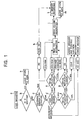
- FIG. 1 is a flow chart showing a disk discriminating method according to the present invention.
- FIG. 2 is a flow chart showing another disk discriminating method.
- FIG. 3 is a side view showing a disk drive device.
- FIG. 4 is an exploded perspective view of a disk magazine.
- FIG. 5 is a side view showing an example of a disk discriminating device.
- FIGS. 1 and 2 are flow charts showing disk discriminating methods according to the present invention, FIG. 3 is a side view showing an arrangement of a disk device, FIG. 4 is a perspective view of a magazine loaded in the disk device, and FIG. 5 is a side view showing an example of a disk discriminating device arranged in the disk.
-
- In a magazine (or a disk package) M shown in FIG. 4, sliding recessed portions Mb are formed on both the inner sides of a case Ma consisting of a synthetic resin, and plural trays T are slidably arranged in the sliding recessed portions Mb. Hooks Ta are integrally formed at the distal end of each tray T. When a disk selecting·
driving mechanism 10 in the disk drive device selects a tray, a drawing member in the disk selecting·driving mechanism 10 is hooked by the hook Ta, and the tray T selected by the drawing member is drawn from the magazine M. - A circular recessed portion Tb having a diameter slightly larger than the diameter (12 cm) of the disk is formed on the upper surface of the tray T, and a disk D is placed on the recessed portion Tb. A notch Tc which causes the central hole of the disk D to be exposed and a fan-shaped notch Td which is connected to the notch Tc and causes the recording surface of the disk D to be exposed downward are formed in the central portion of the recessed portion Tb.
- In the magazine M, reproducing-only ROM disks and recording possible RAM disks are mixed and stored. A tray T on which a RAM disk on which information can be recorded is placed has a projection Te on a side of the tray T, and the projection Te is hooked on a lock mechanism in the magazine M, so that the tray T cannot be drawn. A small projection Mc for canceling a lock is formed on a side of the upper surface of the magazine M. When the magazine M is loaded into the disk device, the small projection Mc is pressed, so that the tray T on which a RAM disk is placed can be drawn. The projection Te is not formed on the tray T on which a ROM disk is not placed, and the tray T can be always manually drawn. When the disk device is designed such that a tray T on which a RAM disk is placed cannot be unexpectedly drawn, the recording surface of the RAM disk can be protected.
- On the surface of the projection Te of the tray T on which the RAM disk is placed, a reflective surface Tf on which a reflective film is formed or on which a reflective film is adhered is formed. A detection window Md is opened in a side of the magazine M, and the reflective surface Tf appears from the detection window Md while the tray T is stored in the magazine M. A tray on which a ROM disk is placed does not have the projection Te and the reflective surface Tf.
- An IC memory M1 serving as a storage element is attached to the bottom surface of the case of the magazine M.
- In a disk device shown in FIG. 3, the magazine M is loaded into a housing 1 from the right in FIG. 3. In the housing 1, an optical detection device 2 opposing the detection window Md of the magazine M shown in FIG. 4, and
photoreflectors 2a whose number is corresponding to the number of trays in the magazine M are arranged on the optical detection device 2. When the magazine M is loaded, thephotoreflectors 2a oppose the side surfaces of the trays T through the detection window Md, respectively. Therefore, when a tray T dedicated to a RAM disk is arranged, the reflective surface Tf is detected, and a reflective surface is not detected on the tray T on which the ROM disk is placed. For this reason, it is possible to detect and identify whether the disk on the tray be a RAM disk or a ROM disk. - In the housing 1, a
contact point 3 is formed. When the magazine M is loaded in the housing 1, the terminal of the IC memory M1 arranged on the bottom of the magazine M is brought into contact with thecontact point 3. A controller 4 to which the optical detection device 2 and thecontact point 3 are connected is arranged in the housing 1, and a memory (RAM) 5 for storing data is arranged in the housing 1. The controller 4 in this disk device is connected to the CPU of a host computer through a BUS line 6. - A disk selecting-
driving mechanism 10 is arranged in the housing 1. The disk selecting-driving mechanism 10 can be moved upward and downward in FIG. 3 to select any tray in the magazine M. A drive chassis 11 arranged in the disk selecting-driving mechanism 10 can be rocked on asupport shaft 12 serving as a fulcrum. By this rocking operation, a disk on a drawn tray is clamped. On the drive chassis 11, aturntable 13 which is fitted in the central hole of the disk D to clamp it, aspindle motor 14 for rotationally driving theturntable 13, and anoptical head 15 are arranged. Thisoptical head 15 has a structure in which objective lenses which are different in numerical aperture can be switched depending on the types of disks, or the numerical aperture of an objective lens can be switched depending on the types of disks. - In the disk selecting-
driving mechanism 10, the drawing member hooked on the hook Ta of the tray T to draw the tray T and a drawing drive section for driving the drawing member. - In addition, a disk
discriminating device 20 shown in FIG. 5 is mounted on the drive chassis 11 or theoptical head 15 of the disk selecting·driving mechanism 10. - Referring to FIG. 5, a disk clamped on the
turntable 13 of the disk selecting-driving mechanism 10 is represented by reference symbol D. Reference symbol Da denotes the surface of the disk. If the disk D is a CD, a CD-R, or a PD, a substrate located between a recording surface R1 and the disk surface Da has a thickness of 1.2 mm. If the disk D is a DVD-RAM or a DVD-ROM, a substrate located between a recording surface R2 and the disk surface Da has a thickness of 0.6 mm. Even if the disk D is any disk, the disk surface Da is supported on the same surface of the turntable. For this reason, in the disk device, the recording surface R1 and the recording surface R2 have different height positions, respectively. - The disk discriminating device having one
light source 21 is shown in FIG. 5. However, thelight source 21 is constituted by two light sources which emit lights having different wavelengths. The wavelength of the light emitted from one light source is 780 nm or approximately 780 nm, and the wavelength of the light emitted from the other light source is 650 nm or approximately 650 nm. Both the light sources are switchably controlled such that the light sources emit lights at different times. A throughhole 22a opened in an aperture means 22 located in front of thelight source 21 is a slit or a square or circular hole which extends in a direction perpendicular to the paper surface to have a predetermined opening width and a length larger than the opening width. Light transmitted through the throughhole 22a is obliquely irradiated on the surface of the disk D. - At a position where light irradiated from the
light source 21 and reflected from the recording surface R1 or R2 of the disk D, a light-receiving means 23 is arranged. The light-receiving means 23 has two light-receivingregions - As an electric circuit arrangement to which the light-receiving means 23 is connected, a subtraction means 24a for calculating a difference between a photoelectric-converted output obtained by the light-receiving
region 23a and a photoelectric-converted output obtained by the light-receivingregion 23b and an addition means 24b for adding the photoelectric-converted outputs obtained by both the light-receivingregions - Of light flex received by the light-receiving means 23, reference symbol X denotes a reflected light flux from the recording surface R1 of a disk including a substrate having a thickness of 1.2 mm, and reference symbol Y denotes a reflected light flux from the recording surface R2 of a disk including a substrate having a thickness of 0.6 mm.
- In this
disk discriminating device 20, the difference between the thicknesses (1.2 mm and 0.6 mm) of the substrates can be discriminated. In addition to this, the difference between the optical reflectances of the recording surfaces R1 and R2 can be discriminated. Furthermore, the difference between the reflectances of the recording surfaces R1 and R2 with respect to light having a wavelength of 780 nm or approximately 780 nm and the difference between the reflectances with respect to light having a wavelength of 650 nm or approximately 650 nm can be discriminated. - When the disk including a substrate having a thickness of 1.2 mm is loaded, and detection light having any one of the wavelengths is irradiated from the
light source 21, the light is reflected by the recording surface R1 located 1.2 mm above the disk surface Da. The reflected light X is received by both the light-receivingregion 23a and the light-receivingregion 23b. When the disk including a substrate having a thickness of 0.6 mm is loaded, and detection light having the wavelength equal to that in a state wherein the 1.2-mm disk is loaded is irradiated from thelight source 21, the light is reflected by the recording surface R2 located 0.6 mm above the disk surface Da. The reflected light Y is received by both the light-receivingregion 23a and the light-receivingregion 23b. - Depending on the difference between the thicknesses of the substrates, i.e., depending on the difference between the heights from the disk surface Da to the recording surfaces R1 and R2, the reflected light X and the reflected light Y are different from each other in a range in which a light flux is irradiated on the light-receiving
means 23. Therefore, the reflected light X and the reflected light Y are different from each other in a ratio of an amount of light received by the light-receivingregion 23a to an amount of light received by the light-receivingregion 23b. - Therefore, when the subtraction means 24a calculates the difference between the amount of light received by the light-receiving
region 23a and the amount of light received by the light-receivingregion 23b, the discriminating means 25 can discriminate the height from the disk surface Da to the recording surface to check whether the height be 1.2 mm or 0.6 mm. For example, in the discriminating means 25, a mean value (difference between amounts of light when the height is 0.9 mm) between the difference between the amount of light received by the light-receivingregion 23a and the amount of light received by the light-receivingregion 23b when the height of the recording surface is 1.2 mm and the difference between the amount of light received from the light-receivingregion 23a and the amount of light received by the light-receivingregion 23b when the height of the recording surface is 0.6 mm is assumed as a threshold value. When the threshold value is compared with an output from the subtraction means 24a, the thicknesses of the substrates can be discriminated. - After the thicknesses of the substrates are discriminated, detection light of 780 nm is given from the
light source 21 or detection light of 650 nm is given, and the difference between the reflectances of the recording surfaces R1 and R2 with respect to respective wavelengths is detected. In this manner, more detailed disk discrimination can be performed. The amounts of reflected light can be detected by an output from the addition means 24b for calculating the sum of the amounts of light received by both the light-receivingregions - A disk discriminating method using the disk device in which the magazine M is loaded will be described below with reference to FIG. 1.
- The magazine M is loaded in the disk device (step (a)), magazine drive software is started by an Icon on the display screen of a computer. Immediately after the start, the IC memory M1 on the bottom of the magazine M is accessed through the
contact point 3 shown in FIG. 3. When the magazine M is in an initial state, and no database is stored in the IC memory M1, it is displayed on the display that the magazine M is a magazine in an initial state, and a display representing whether a discriminating operation for the disks in the magazine M appears be started (step (b)). In response to this display, when a mark is adjusted to "YES", and an input button (e.g., a click button of a mouse) is pressed, the disk discriminating operation is started. The following disk discriminating operation is executed by the process of the controller 4 arranged in the disk device. Also, each detection output may be sent to the CPU of the host computer through the BUS line 6, and the following disk discriminating operation may be executed by the CPU. - In step (c) in this disk discriminating operation, an output from the optical detection device 2 shown in FIG. 3 is given to the controller 4. When a tray T dedicated to a RAM disk is stored in the magazine M, the reflective surface Tf formed on the side surface of the tray T appears from the detection window Md on the side surface of the magazine M as shown in FIG. 4, and reflected light of light spontaneously emitted from the
photoreflector 2a is detected. At this time, trays dedicated to the RAM disk and trays dedicated to the ROM disk can be known in plural trays. - After detection information in the optical detection device 2 is given to the controller 4, the disk selecting·driving
mechanism 10 is started by a control operation of the controller 4 to select a disk in the magazine M. The trays are sequentially drawn by the disk selecting·drivingmechanism 10 one by one. - When the reflective surface Tf of the tray T is detected by the optical detection device 2, a disk placed on this tray T is determined as a RAM disk. However, the RAM disk may be a PD (power disk) or a DVD-RAM (digital-versatile-disk-RAM). In this case, a tray dedicated by the RAM disk is drawn. a disk is loaded on the
turntable 13, and data recorded on the disk is read by theoptical head 15, so that the disk is discriminated on the basis of the recording format to check whether the disk be a PD or a DVD-RAM. Theoptical head 15 has a structure in which objective lenses can be switched, or the numerical aperture of an objective lens can be switched. If the optical detection device 2 determines that a RAM disk is placed on the tray, the objective lens in theoptical head 15 is switched to an objective lens suitable for a PD or a DVD-RAM at any time, or the numerical aperture of the objective lens is switched, so that the data is read. - When it is determined on the basis of the output from the optical detection device 2 in step (c) that the reflective surface Tf of the tray T is not detected, this tray T is determined as a tray dedicated to the ROM disk.
- When the tray T dedicated to the ROM disk is drawn by the disk selecting·driving
mechanism 10, and the disk D is loaded on theturntable 13, thelight source 21 of thedisk discriminating device 20 shown in FIG. 5 obliquely irradiates detection light on the disk surface. Depending on whether the reflected light be X or Y, the differences of amounts of light received by the light-receivingregions - Here, the tray T having a projection Te in the magazine M shown in FIG. 4 is dedicated to the RAM disk. As described above, the projection Te is locked by the lock mechanism in the magazine M to prevent this tray from being manually drawn. However, when the projection Te appearing from the detection window Md of the magazine M is pressed with a tool such as a screwdriver to break or transform the projection Te, even the tray dedicated to the RAM disk can be freely drawn out of the magazine M. In this system, when the tray T is drawn by breaking or transforming the projection Te for some reason, thereafter, the recording surface of the DVD-RAM may stain, and writing precision may be degraded. For this reason, even if a DVD-RAM is placed on this tray T, after the Te is broken, the DVD-RAM is handled as a ROM on which recording is not performed. The disk device is designed such that the optical detection device 2 cannot detect the reflective surface Tf when the projection Te is broken or transformed.
- Therefore, if the reflective surface Tf is not detected in step (c) in FIG. 1 so that the tray is determined as a tray dedicated to the ROM disk, and if it is determined in step (d) that the substrate of the disk has a thickness smaller than 0.9 mm (0.6 mm), a disk on this tray T may be a DVD-ROM or a DVD-RAM which is handled as a ROM described above. For this reason, in this case, in step (e), detection light having a wavelength of 780 nm is irradiated from the
light source 21 shown in FIG. 5, and a reflectance is examined on the basis of a detection output from the addition means 24b. When the reflectance is higher than 50%, the disk on this tray is discriminated as a DVD-ROM. When the reflectance is lower than 50%, the disk on this tray is discriminated as a DVD-RAM handled as a ROM. - If the thickness of the disk is discriminated such that the thickness is larger than 0.9 mm and equal to 1.2 mm in step (d), in step (f), detection light having a wavelength of 780 nm is irradiated from the
light source 21 shown in FIG. 5, and a reflectance is detected on the basis of an addition output from the addition means 24b. If it is determined that the reflectance exceeds 50%, the light from thelight source 21 is switched in step (g) to give detection light having a wavelength of 650 nm to the disk. When the reflectance at this time exceeds 50%, the disk placed on the tray dedicated to the ROM disk is discriminated as a CD. However, when the reflectance with respect to the detection light having a wavelength of 650 nm is lower than 50% in step (g), the disk is discriminated as a CD-R which is erroneously placed on the tray dedicated to the ROM disk. An error message is displayed on the display of the host computer, and the tray on which the disk is placed is forcibly returned into the magazine M. - When the thickness of the substrate of the disk cannot be detected in step (d), it is determined that no disk is placed on the tray, and an error message is displayed on the display. If it is determined that the reflectance with respect to detection light having a wavelength of 780 nm is lower than 50% in step (f), it is determined that a disk which is not supposed to be used is placed on the tray, an error message is displayed as described above, and the tray is forcibly returned into the magazine M.
- Immediately after the types of the disks arranged on the trays T in the magazine M are discriminated by the discriminating means 25 as described above, information of every disk is read by an optical disk. When the disk is a PD, FAT is read (step (h)). When the disk is a DVD-RAM, a DVD-ROM, a DVD-RAM handled as a ROM, or a CD, TOC information is read (step (i)). In addition, a Volume Descripter is read as contents information (step (j)).
- As described above, all the trays T in the magazine M are drawn, and discrimination for the types of the disks and reading of the contents information are performed. However, the type information and contents information of each disk are written in the memory 5 in the disk device shown in FIG. 3 at any time, and are converted into a database in a predetermined format. All the trays are drawn, and the type information and the contents information are written in the memory 5 in step (m) to be converted into a database. Thereafter, in step (k), the recorded contents in the memory 5 are transferred to the IC memory M1 arranged on the bottom of the magazine M to be written in the IC memory M1. In this writing operation, only the disk type information may be transcribed in the IC memory M1.
- After data is recorded on the IC memory M1 of the disk device in step (m), the data is sent to the host computer through the BUS line 6, and an Icon related to identification of each disk is displayed on the display. When the Icon of a specific disk is selected, and an operation button (click button of the mouse) is pressed, the contents information of the disk (FAT information or Volume Descripter) is displayed on the display. When the Icon corresponding to a specific disk is selected, the tray of the selected disk is drawn from the magazine M, software related to the disk is started, and a reading/recording operation of information from/on the disk is made possible.
- In step (k), after the disk type information and the contents information are converted into a database, the database is recorded on the IC memory M1 of the magazine M. However, when the magazine M has no IC memory M1, in step (k), a tray T on which a predetermined programmable disk, e.g., a DVD-RAM is placed is drawn, and the disk type information and the contents information are recorded in a predetermined recording region of the disk.
- When the magazine M including the IC memory M1 (or predetermined disk) in which the type information and the contents information are written as described above is removed from the disk device, and the magazine is loaded in the disk device again, in step (b), the IC memory M1 is accessed from the controller 4, and it is determined that write information is in the IC memory. In step (n), the data recorded on the IC memory M1 is loaded on the memory 5 in the disk device. In this manner, the information can be accessed from the CPU of the computer, and an Icon related to the type of each disk is displayed on the display. In addition, contents information can be displayed, and, immediately, a reproducing operation or a recording operation can be performed to the disks.
- When the magazine M has no IC memory M1, and type information and contents information are recorded on a specific disk, the recorded disk is reproduced in step (b), so that the identification information or contents information recorded on the disk is read to be stored in the memory 5.
- FIG. 2 is a flow chart showing another processing method.
- Referring to FIG. 2, the ID code of a magazine is recorded on the small-capacity IC memory M1 installed on the bottom surface of the case of the magazine M or an identification recording means, attached to the case in place of the IC memory, for a bar code or the like, so that different magazine have different code numbers, respectively. As another identification recording means, several-bit identification holes may be formed in the magazine M. The presence/absence of the holes may be detected by a contact type or non-contact type detecting member arranged on the disk device side. When an ID mark such as a bar code is added, the ID mark may be read by a scanner arranged in the housing 1.
- The ID code of the loaded magazine M is read in step (s) shown in FIG. 2, and a database corresponding to the ID code is discriminated to check whether the database be stored in the memory 5 in step (o). When the database is not stored, identification for checking whether the tray be a tray for a RAM disk or a tray for a ROM disk and an identifying operation for the respective disks are performed in the steps following step (c). After the discrimination for the types of the disks and reading of the contents information. the identification information of the disks and contents information such as TOC are converted into a database together with the identification code (ID code) of the magazine in step (p), and the database is stored in the memory 5 in step (q), otherwise, the data converted into the database are stored in the storage section of the host computer.
- Although the database may be constituted by the identification code of the magazine and the disk type information, the contents information is preferably added.
- When the magazine M in which the disk discriminating operation and the storage of the database are completed is loaded in the disk device again, in step (o) in FIG. 2. the memory 5 is accessed to confirm that the database corresponding to the ID code of the magazine is stored. In this case, a discriminating operation performed in steps following step (c) is not performed, and the database stored in the memory 5 is loaded to be stored in the host computer, so that the disk device can be driven depending on the types of the respective disks.
- In the example shown in FIG. 1, all the pieces of identification information of the disks are stored in the IC memory M1. In FIG. 2, an ID code for identifying a magazine is stored in the IC memory M1 or the like. However, only identification information representing whether each disk be a ROM disk or a RAM disk may be stored in the IC memory M1 in advance, or only information representing whether the disks in the magazine be ROM disks or RAM disks may be stored in the memory 5 in correspondence with the ID code, recorded on the IC memory M1, for identifying a magazine. In this case, in step (c) in FIGS. 1 and 2, it is determined on the basis of the stored contents in the IC memory M1 or the stored contents in the memory 5 whether a specific disk in the magazine be a ROM disk or a RAM disk. Thereafter, the types of the respective disks are discriminated in steps following step (d).
- The present invention achieves the following advantages.
- 1) In a disk device in which a magazine in which ROM disks and RAM disks are mixed and stored is loaded, when the magazine is loaded, the types and contents information of the disks in the magazine are detected and recorded on a storage section of the magazine. For this reason, when the magazine is loaded again, the information is read immediately, and disk drive can be started.
- 2) In a disk device in which a magazine in which ROM disks, RAM disks, and the like are mixed and stored is loaded, when the magazine is loaded, identification of the magazine is performed, and a database corresponding to the identification code can be extracted, so that the types and contents information of the disks in the magazine can be recognized. Therefore, when the magazine is loaded again, disk drive can be started immediately.
- 3) In a disk device in which a magazine in which ROM disks and RAM disks are mixed and stored is loaded, when the magazine is loaded, after identification is performed to check whether the disks be ROM disks or RAM disk, a discriminating operation for the respective disks is started. For this reason, the types of the disks can be discriminated at high precision. A problem that a laser beam which adversely affects the recording surface of the disk is erroneously irradiated on the recording surface does not arise.
-
Claims (1)
- A disk discriminating method for a disk device having a magazine having both a recordable disk and a reproducing-only disk which can be stored in said magazine, whereby respective disks are discriminated on the basis of information recorded on said loaded magazine to check whether the disks in said magazine are recordable disks or reproducing-only disks, each disk is drawn from said magazine after the discrimination, and the type of the corresponding disk is discriminated by at least one method selected from: a) detection of reflectance of a recording surface of the disk, b) detection of thickness of a substrate in which the recording surface of the disk is formed, and c) reading of signals recorded on the disk, and wherein trays on which the disks are placed can be withdrawably stored in said magazine, identification information representing whether the corresponding disk is a recordable disk or a reproducing-only disk being added to each tray.
Applications Claiming Priority (9)
| Application Number | Priority Date | Filing Date | Title |
|---|---|---|---|
| JP10025297 | 1997-04-17 | ||
| JP9100252A JPH10293963A (en) | 1997-04-17 | 1997-04-17 | Disk discriminating method |
| JP9100235A JPH10293962A (en) | 1997-04-17 | 1997-04-17 | Disk discriminating method |
| JP100235/97 | 1997-04-17 | ||
| JP100252/97 | 1997-04-17 | ||
| JP10023597 | 1997-04-17 | ||
| JP141724/97 | 1997-05-30 | ||
| JP9141724A JPH10334572A (en) | 1997-05-30 | 1997-05-30 | Disk discriminating method |
| JP14172497 | 1997-05-30 |
Publications (2)
| Publication Number | Publication Date |
|---|---|
| EP0872836A1 EP0872836A1 (en) | 1998-10-21 |
| EP0872836B1 true EP0872836B1 (en) | 2004-12-01 |
Family
ID=27309171
Family Applications (1)
| Application Number | Title | Priority Date | Filing Date |
|---|---|---|---|
| EP98302431A Expired - Lifetime EP0872836B1 (en) | 1997-04-17 | 1998-03-30 | Optical disk discriminating method |
Country Status (6)
| Country | Link |
|---|---|
| US (1) | US6130744A (en) |
| EP (1) | EP0872836B1 (en) |
| KR (1) | KR100269985B1 (en) |
| CN (1) | CN1196552A (en) |
| DE (1) | DE69827868T2 (en) |
| TW (1) | TW469424B (en) |
Families Citing this family (13)
| Publication number | Priority date | Publication date | Assignee | Title |
|---|---|---|---|---|
| JP3786548B2 (en) * | 1999-09-10 | 2006-06-14 | パイオニア株式会社 | Disc player |
| US6420692B1 (en) * | 1999-11-12 | 2002-07-16 | Terastor Corporation | Zig-zag-patterned position sensor system |
| DE60304924T2 (en) | 2002-04-01 | 2007-01-11 | Sony Corp. | A method of initializing a mini disk, and recording and reproducing methods and recording and reproducing apparatus |
| US7340749B2 (en) * | 2002-12-03 | 2008-03-04 | Hewlett-Packard Development Company, L.P. | Method and apparatus to detect presence of or a size of a data cartridge |
| TWI227885B (en) * | 2002-12-24 | 2005-02-11 | Lite On It Corp | Adjustment system of compact disc player using screen for display and method thereof |
| KR100987437B1 (en) | 2003-08-14 | 2010-10-13 | 엘지전자 주식회사 | Recording medium,recording method and recording apparatus |
| KR101102384B1 (en) * | 2003-08-14 | 2012-01-05 | 엘지전자 주식회사 | Optical disc and recording method, recording/reproducing apparatus and recording/reproducing system |
| GB2406959A (en) * | 2003-10-09 | 2005-04-13 | Hewlett Packard Development Co | A data storage magazine with a memory |
| JP2006082397A (en) * | 2004-09-16 | 2006-03-30 | Fuji Photo Film Co Ltd | Printer, image output device, and method for guiding insertion port of recording medium |
| US7277278B2 (en) * | 2004-10-12 | 2007-10-02 | Thermaltake Inc. | Hinged panel and disc drive for a computer |
| US7673309B2 (en) * | 2005-01-20 | 2010-03-02 | Hie Electronics, Inc. | Scalable integrated high density optical data/media storage delivery system |
| JP6008314B2 (en) * | 2012-03-28 | 2016-10-19 | パナソニックIpマネジメント株式会社 | Disk unit |
| WO2014054216A1 (en) | 2012-10-01 | 2014-04-10 | パナソニック株式会社 | Recording/playback device |
Family Cites Families (18)
| Publication number | Priority date | Publication date | Assignee | Title |
|---|---|---|---|---|
| AU2892084A (en) * | 1983-06-02 | 1984-12-06 | Andros Research Ltd. | Reading 2 dimensional array |
| US4792865A (en) * | 1984-08-24 | 1988-12-20 | Eastman Kodak Company | Disk container supporting a detachable memory |
| EP0265167B1 (en) * | 1986-10-15 | 1997-01-02 | Pioneer Electronic Corporation | Disk player with disk magazine |
| JPS63109366U (en) * | 1986-12-27 | 1988-07-14 | ||
| JPH01303691A (en) * | 1988-05-31 | 1989-12-07 | Matsushita Electric Ind Co Ltd | Optical multi-disk reproducing device |
| JPH0223564A (en) * | 1988-07-11 | 1990-01-25 | Onkyo Corp | Cd autochangeable player |
| JP3007378B2 (en) * | 1990-05-08 | 2000-02-07 | パイオニア株式会社 | Disc selection control device for multi-disc player |
| US5235581A (en) * | 1990-08-09 | 1993-08-10 | Matsushita Electric Industrial Co., Ltd. | Optical recording/reproducing apparatus for optical disks with various disk substrate thicknesses |
| JP2786372B2 (en) * | 1992-05-20 | 1998-08-13 | 富士通株式会社 | Library device |
| US5357495A (en) * | 1992-07-02 | 1994-10-18 | Tandberg Data A/S | Stacker/autoloader system with intelligent media storage magazine control |
| JPH06131855A (en) * | 1992-10-19 | 1994-05-13 | Sony Corp | Disk reproducing device |
| JP3172636B2 (en) * | 1994-07-27 | 2001-06-04 | 株式会社ケンウッド | Changer type disc player |
| US5914929A (en) * | 1994-09-07 | 1999-06-22 | Sanyo Electric Co., Ltd. | Optical disk recording/playback device with means to recognize, read from and record to multiple types of optical disk types |
| US5903538A (en) * | 1994-12-14 | 1999-05-11 | Matsushita Electric Industrial Co., Ltd. | Automatic disk change apparatus and disk tray for the apparatus |
| JP3525572B2 (en) * | 1995-09-12 | 2004-05-10 | 松下電器産業株式会社 | Automatic medium exchange device and recording / reproducing device |
| US5917791A (en) * | 1995-11-30 | 1999-06-29 | Sanyo Electric Co., Ltd. | Apparatus for discriminating optical recording media of different thicknesses from each other and reproducing information therefrom |
| JPH09212984A (en) * | 1996-02-02 | 1997-08-15 | Canon Inc | Optical-disk changer |
| JP3276566B2 (en) * | 1996-09-25 | 2002-04-22 | アルプス電気株式会社 | Disk unit |
-
1998
- 1998-03-16 TW TW087103822A patent/TW469424B/en not_active IP Right Cessation
- 1998-03-30 DE DE69827868T patent/DE69827868T2/en not_active Expired - Fee Related
- 1998-03-30 EP EP98302431A patent/EP0872836B1/en not_active Expired - Lifetime
- 1998-04-07 US US09/056,213 patent/US6130744A/en not_active Expired - Fee Related
- 1998-04-15 KR KR1019980013447A patent/KR100269985B1/en not_active IP Right Cessation
- 1998-04-17 CN CN98101559A patent/CN1196552A/en active Pending
Also Published As
| Publication number | Publication date |
|---|---|
| EP0872836A1 (en) | 1998-10-21 |
| DE69827868D1 (en) | 2005-01-05 |
| KR100269985B1 (en) | 2000-10-16 |
| CN1196552A (en) | 1998-10-21 |
| KR19980081430A (en) | 1998-11-25 |
| US6130744A (en) | 2000-10-10 |
| TW469424B (en) | 2001-12-21 |
| DE69827868T2 (en) | 2005-12-22 |
Similar Documents
| Publication | Publication Date | Title |
|---|---|---|
| EP0872836B1 (en) | Optical disk discriminating method | |
| JP3276566B2 (en) | Disk unit | |
| EP0833327B1 (en) | Disc package | |
| JP3308455B2 (en) | Disk unit | |
| JP3308454B2 (en) | Disk package | |
| JP3338303B2 (en) | Disk package | |
| JP3264839B2 (en) | Disk package | |
| JPH10334572A (en) | Disk discriminating method | |
| JPH10293963A (en) | Disk discriminating method | |
| JPH10293962A (en) | Disk discriminating method | |
| JP4067536B2 (en) | Optical disc apparatus and disc discrimination method | |
| JPH0536234A (en) | Disk cartridge and disk recording and/or reproducing device | |
| JP4287847B2 (en) | Optical disc apparatus and optical disc discrimination method | |
| KR19990057689A (en) | Optical disc player | |
| JP2003272274A (en) | Disk auto changer apparatus | |
| JP2010040089A (en) | Optical disk device and optical disk processing system having the same |
Legal Events
| Date | Code | Title | Description |
|---|---|---|---|
| PUAI | Public reference made under article 153(3) epc to a published international application that has entered the european phase |
Free format text: ORIGINAL CODE: 0009012 |
|
| AK | Designated contracting states |
Kind code of ref document: A1 Designated state(s): DE FR GB NL |
|
| AX | Request for extension of the european patent |
Free format text: AL;LT;LV;MK;RO;SI |
|
| 17P | Request for examination filed |
Effective date: 19981016 |
|
| AKX | Designation fees paid |
Free format text: DE FR GB NL |
|
| 17Q | First examination report despatched |
Effective date: 20030303 |
|
| RTI1 | Title (correction) |
Free format text: OPTICAL DISK DISCRIMINATING METHOD |
|
| GRAP | Despatch of communication of intention to grant a patent |
Free format text: ORIGINAL CODE: EPIDOSNIGR1 |
|
| GRAS | Grant fee paid |
Free format text: ORIGINAL CODE: EPIDOSNIGR3 |
|
| GRAA | (expected) grant |
Free format text: ORIGINAL CODE: 0009210 |
|
| AK | Designated contracting states |
Kind code of ref document: B1 Designated state(s): DE FR GB NL |
|
| PG25 | Lapsed in a contracting state [announced via postgrant information from national office to epo] |
Ref country code: NL Free format text: LAPSE BECAUSE OF FAILURE TO SUBMIT A TRANSLATION OF THE DESCRIPTION OR TO PAY THE FEE WITHIN THE PRESCRIBED TIME-LIMIT Effective date: 20041201 |
|
| REG | Reference to a national code |
Ref country code: GB Ref legal event code: FG4D |
|
| REF | Corresponds to: |
Ref document number: 69827868 Country of ref document: DE Date of ref document: 20050105 Kind code of ref document: P |
|
| NLV1 | Nl: lapsed or annulled due to failure to fulfill the requirements of art. 29p and 29m of the patents act | ||
| PLBE | No opposition filed within time limit |
Free format text: ORIGINAL CODE: 0009261 |
|
| STAA | Information on the status of an ep patent application or granted ep patent |
Free format text: STATUS: NO OPPOSITION FILED WITHIN TIME LIMIT |
|
| ET | Fr: translation filed | ||
| 26N | No opposition filed |
Effective date: 20050902 |
|
| PGFP | Annual fee paid to national office [announced via postgrant information from national office to epo] |
Ref country code: GB Payment date: 20070227 Year of fee payment: 10 |
|
| PGFP | Annual fee paid to national office [announced via postgrant information from national office to epo] |
Ref country code: DE Payment date: 20070522 Year of fee payment: 10 |
|
| PGFP | Annual fee paid to national office [announced via postgrant information from national office to epo] |
Ref country code: FR Payment date: 20070320 Year of fee payment: 10 |
|
| GBPC | Gb: european patent ceased through non-payment of renewal fee |
Effective date: 20080330 |
|
| REG | Reference to a national code |
Ref country code: FR Ref legal event code: ST Effective date: 20081125 |
|
| PG25 | Lapsed in a contracting state [announced via postgrant information from national office to epo] |
Ref country code: DE Free format text: LAPSE BECAUSE OF NON-PAYMENT OF DUE FEES Effective date: 20081001 |
|
| PG25 | Lapsed in a contracting state [announced via postgrant information from national office to epo] |
Ref country code: FR Free format text: LAPSE BECAUSE OF NON-PAYMENT OF DUE FEES Effective date: 20080331 |
|
| PG25 | Lapsed in a contracting state [announced via postgrant information from national office to epo] |
Ref country code: GB Free format text: LAPSE BECAUSE OF NON-PAYMENT OF DUE FEES Effective date: 20080330 |