EP0832418B1 - Sensitive and fast response optical detection of transient motion from a scattering surface by two-wave mixing - Google Patents
Sensitive and fast response optical detection of transient motion from a scattering surface by two-wave mixing Download PDFInfo
- Publication number
- EP0832418B1 EP0832418B1 EP97919218A EP97919218A EP0832418B1 EP 0832418 B1 EP0832418 B1 EP 0832418B1 EP 97919218 A EP97919218 A EP 97919218A EP 97919218 A EP97919218 A EP 97919218A EP 0832418 B1 EP0832418 B1 EP 0832418B1
- Authority
- EP
- European Patent Office
- Prior art keywords
- real
- holographic material
- time
- received light
- time holographic
- Prior art date
- Legal status (The legal status is an assumption and is not a legal conclusion. Google has not performed a legal analysis and makes no representation as to the accuracy of the status listed.)
- Expired - Lifetime
Links
- 230000033001 locomotion Effects 0.000 title claims description 56
- 230000001052 transient effect Effects 0.000 title claims description 44
- 230000004044 response Effects 0.000 title claims description 16
- 238000001514 detection method Methods 0.000 title description 18
- 230000003287 optical effect Effects 0.000 title description 14
- 239000000463 material Substances 0.000 claims description 60
- 239000013078 crystal Substances 0.000 claims description 37
- 230000005684 electric field Effects 0.000 claims description 16
- 238000000034 method Methods 0.000 claims description 16
- 230000010287 polarization Effects 0.000 claims description 14
- 239000000835 fiber Substances 0.000 claims description 12
- 239000013307 optical fiber Substances 0.000 claims description 7
- 230000001939 inductive effect Effects 0.000 claims description 6
- MARUHZGHZWCEQU-UHFFFAOYSA-N 5-phenyl-2h-tetrazole Chemical compound C1=CC=CC=C1C1=NNN=N1 MARUHZGHZWCEQU-UHFFFAOYSA-N 0.000 claims description 5
- GPXJNWSHGFTCBW-UHFFFAOYSA-N Indium phosphide Chemical compound [In]#P GPXJNWSHGFTCBW-UHFFFAOYSA-N 0.000 claims description 4
- 238000010438 heat treatment Methods 0.000 claims description 4
- 239000004065 semiconductor Substances 0.000 claims description 4
- 230000008878 coupling Effects 0.000 claims description 3
- 238000010168 coupling process Methods 0.000 claims description 3
- 238000005859 coupling reaction Methods 0.000 claims description 3
- 230000005284 excitation Effects 0.000 claims description 3
- 238000001816 cooling Methods 0.000 claims 1
- 230000035945 sensitivity Effects 0.000 description 14
- 238000002604 ultrasonography Methods 0.000 description 7
- 230000010363 phase shift Effects 0.000 description 6
- 230000000694 effects Effects 0.000 description 5
- 238000005286 illumination Methods 0.000 description 3
- 230000001965 increasing effect Effects 0.000 description 3
- 230000007935 neutral effect Effects 0.000 description 3
- 229910001218 Gallium arsenide Inorganic materials 0.000 description 2
- XEEYBQQBJWHFJM-UHFFFAOYSA-N Iron Chemical compound [Fe] XEEYBQQBJWHFJM-UHFFFAOYSA-N 0.000 description 2
- 238000010521 absorption reaction Methods 0.000 description 2
- 230000006978 adaptation Effects 0.000 description 2
- 238000004458 analytical method Methods 0.000 description 2
- 238000013459 approach Methods 0.000 description 2
- 230000015556 catabolic process Effects 0.000 description 2
- 230000008859 change Effects 0.000 description 2
- 230000007423 decrease Effects 0.000 description 2
- 238000011896 sensitive detection Methods 0.000 description 2
- 230000035939 shock Effects 0.000 description 2
- 230000008901 benefit Effects 0.000 description 1
- 230000005540 biological transmission Effects 0.000 description 1
- 230000015572 biosynthetic process Effects 0.000 description 1
- 239000000919 ceramic Substances 0.000 description 1
- 238000004891 communication Methods 0.000 description 1
- 238000009792 diffusion process Methods 0.000 description 1
- 238000006073 displacement reaction Methods 0.000 description 1
- 230000008030 elimination Effects 0.000 description 1
- 238000003379 elimination reaction Methods 0.000 description 1
- 238000001093 holography Methods 0.000 description 1
- 230000001976 improved effect Effects 0.000 description 1
- 238000007689 inspection Methods 0.000 description 1
- 238000005305 interferometry Methods 0.000 description 1
- 229910052742 iron Inorganic materials 0.000 description 1
- 238000004519 manufacturing process Methods 0.000 description 1
- 238000005259 measurement Methods 0.000 description 1
- 230000028161 membrane depolarization Effects 0.000 description 1
- 229910052751 metal Inorganic materials 0.000 description 1
- 239000002184 metal Substances 0.000 description 1
- 150000002739 metals Chemical class 0.000 description 1
- 229920000642 polymer Polymers 0.000 description 1
- 229920013657 polymer matrix composite Polymers 0.000 description 1
- 239000011160 polymer matrix composite Substances 0.000 description 1
- 230000008569 process Effects 0.000 description 1
- 238000004886 process control Methods 0.000 description 1
- 238000012545 processing Methods 0.000 description 1
- 230000001902 propagating effect Effects 0.000 description 1
- 238000003908 quality control method Methods 0.000 description 1
- 239000007787 solid Substances 0.000 description 1
- 230000001960 triggered effect Effects 0.000 description 1
- 229910052720 vanadium Inorganic materials 0.000 description 1
- LEONUFNNVUYDNQ-UHFFFAOYSA-N vanadium atom Chemical compound [V] LEONUFNNVUYDNQ-UHFFFAOYSA-N 0.000 description 1
Images

Classifications
-
- G—PHYSICS
- G01—MEASURING; TESTING
- G01B—MEASURING LENGTH, THICKNESS OR SIMILAR LINEAR DIMENSIONS; MEASURING ANGLES; MEASURING AREAS; MEASURING IRREGULARITIES OF SURFACES OR CONTOURS
- G01B9/00—Measuring instruments characterised by the use of optical techniques
- G01B9/02—Interferometers
- G01B9/021—Interferometers using holographic techniques
- G01B9/027—Interferometers using holographic techniques in real time
-
- G—PHYSICS
- G01—MEASURING; TESTING
- G01P—MEASURING LINEAR OR ANGULAR SPEED, ACCELERATION, DECELERATION, OR SHOCK; INDICATING PRESENCE, ABSENCE, OR DIRECTION, OF MOVEMENT
- G01P3/00—Measuring linear or angular speed; Measuring differences of linear or angular speeds
- G01P3/36—Devices characterised by the use of optical means, e.g. using infrared, visible, or ultraviolet light
- G01P3/366—Devices characterised by the use of optical means, e.g. using infrared, visible, or ultraviolet light by using diffraction of light
Description
Furthermore, this principle has been applied to the detection of ultrasound using a BSO crystal and that work was reported in Japanese Journal of Applied Physics, vol. 34, pp. 3737-3740, 1995, title :" Optical measurement of ultrasonic nanometer motion of rough surface by two-wave mixing in BSO", authors : Tokuyuki Honda, Toshihisa Yamashita and Hirokazu Matsumoto."
wherein said pump beam being of sufficiently high intensity to cause the response time of the real-time holographic material to be substantially shorter than a characteristic time defined as the time during which the phase of the received light, on average across its spatial distribution or locally, is not substantially changed; and,
Claims (23)
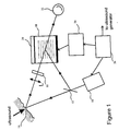
- A method of optically detecting transient motion from the surface of a workpiece having a predetermined duration, comprising the steps of:a) directing a beam generated by a laser onto said surface;b) receiving a light beam that has been reflected or scattered by said surface;c) allowing the received light beam to interfere with a pump beam removed from the laser, inside a real-time holographic material, so as to form a grating diffracting the pump beam into a reference beam, which interferes at the output of the real-time holographic material with the received light beam, so as to produce a signal representative of the surface transient motion;d) applying onto said real-time holographic material, an electric field of sufficient magnitude to increase substantially the intensity of said reference beam and to give to this beam a phase differing substantially from the phase of said received light beam, wherein the step of applying the electric field is performed prior to the transient motion to be detected, for a time interval sufficiently long to capture the transient motion but sufficiently short to avoid excessive heating of the real-time holographic material;
wherein
said pump beam being of sufficiently high intensity to cause the response time of the real-time holographic material to be substantially shorter than a characteristic time defined as the time during which the phase of the received light, on average across its spatial distribution or locally, is not substantially changed; and,e) inducing surface transient motion at a predetermined time after electric field application onto the real-time holographic material, and wherein the pump beam intensity, applied field amplitude and applied field duration are such, as to avoid real-time holographic material catastrophic failure. - A method as defined in claim 1, wherein the received light beam is polarized prior to performing step (c).
- A method as defined in claim 1, wherein the laser is pulsed, with a pulse duration which exceeds the duration of the surface transient motion and exceeds said characteristic time, while being less than the duration of application of the electric field.
- A method as defined in claim 2, wherein the real-time holographic material is a crystal and is cut and oriented in such a way to ensure the reference beam is polarized perpendicularly to said received light beam.
- A method as defined in claim 1, wherein the real-time holographic material is a photorefractive material.
- A method as defined in claim 2, where the pump beam removed from the laser beam is transmitted by an optical fiber and is polarized prior to allowing the received light beam to interfere with a pump beam removed from the laser, inside a real-time holographic material.
- A method as defined in claim 1, wherein the pump beam removed from the laser beam and the received light beam are both transmitted by optical fibers and are coupled into the real-time holographic material substantially unpolarized.
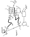
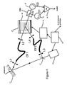
- An apparatus for optically detecting transient motion from the surface of a workpiece having a predetermined duration, which comprises:a) means for inducing said transient motion;b) means for generating and directing a laser beam onto said surface;c) means for receiving light reflected or scattered by said surface and phase modulated by its transient motion;e) real-time holographic material element provided with electrodes and arranged to collect a received light beam;f) means for removing directly from the laser beam a pump beam of sufficiently high intensity to cause the response time of the real-time holographic material element to be substantially shorter than a characteristic time defined as the time during which the phase of the received light, on average across its spatial distribution or locally, is not substantially changed;g) means for causing the received light beam to interfere inside the real-time holographic material element with said pump beam, so as to form a grating diffracting said pump beam into a reference beam, which interferes at the output of the real-time holographic material with the received light beam, so as to produce a signal representative of the surface transient motion;h) means for applying onto said real-time holographic material element electrodes a pulsed electrical voltage of sufficient magnitude to increase substantially said reference beam intensity with a phase also differing substantially from the phase of said transmitted received light beam;i) means for timing the triggering of the excitation of the transient motion and the application of the electrical voltage, the voltage being turned on before the triggering of said means for inducing transient motion and turned off after end of transient motion, while keeping turn-on duration minimum to avoid heating of the real-time holographic material.
- An apparatus as defined in claim 8, further including first polarizing means to polarize received light beam before coupling into the real-time holographic material element.
- An apparatus as defined in claim 8, wherein said means for generating a laser beam is pulsed, with a pulse duration exceeding the duration of the surface transient motion and exceeding said characteristic time, while being less than the duration of application of the electrical voltage, the triggering of the laser pulse being controlled by said timing means.
- An apparatus as defined in claim 8, wherein the real-time holographic material element is a photorefractive crystal.
- An apparatus as defined in claim 11, wherein the photorefractive crystal material is a sillenite.
- An apparatus as defined in claim 11, wherein the photorefractive crystal material is a semiconductor.
- An apparatus as defined in claim 13, wherein the photorefractive crystal material is doped Indium Phosphide.
- An apparatus as defined in claim 13, wherein the photorefractive crystal material is doped Cadmium Telluride.
- An apparatus as defined in claim 8, further including a thermoelectric cooling means upon which is mounted the real-time holographic material element.
- An apparatus as defined in claim 8, wherein the magnitude of the applied voltage is such that the reference beam is substantially in quadrature with said transmitted received light beam.
- An apparatus as defined in claim 9, wherein the real-time holographic material element is a crystal and is cut and oriented in such a way to produce said reference beam polarized perpendicularly to said transmitted received light beam, the interference described in (g) of claim 8 being performed with a polarizing beam splitter means, which provides two output signal beams.
- An apparatus as defined in claim 18, further comprising two photodetectors to collect said output signal beams, these photodetectors for providing signals to a differential amplifier means, for providing a signal representative of the surface transient motion with minimum background signal offset and spurious contributions.
- An apparatus as defined in claim 19, further comprising an adjustable wave plate to maximize the signal representative of surface transient motion at the output of said differential amplifier means.
- An apparatus as defined in claim 9, further comprising an optical fiber for transmitting said pump beam to the real-time holographic material element and second polarizing means ahead of the real-time holographic material element for providing a same polarization as said first polarizing means.
- An apparatus as defined in claim 8, further comprising optical fibers for transmitting said pump beam and said received light beam for coupling onto the real-time holographic material element, the outputs of these two fibers ahead of the real-time holographic material element being substantially unpolarized and coupled as such into the real-time holographic material element.
- An apparatus as defined in claim 22, further comprising polarizing beam splitting means, for providing two output signal beams and two photodetectors to receive these output signal beams, these photodetectors for providing their signals to a differential amplifier means, for providing a signal representative of the surface transient motion.
Applications Claiming Priority (3)
| Application Number | Priority Date | Filing Date | Title |
|---|---|---|---|
| US08/632,073 US5680212A (en) | 1996-04-15 | 1996-04-15 | Sensitive and fast response optical detection of transient motion from a scattering surface by two-wave mixing |
| PCT/CA1997/000290 WO1997039305A1 (en) | 1996-04-15 | 1997-04-09 | Sensitive and fast response optical detection of transient motion from a scattering surface by two-wave mixing |
| US632073 | 2000-08-04 |
Publications (2)
| Publication Number | Publication Date |
|---|---|
| EP0832418A1 EP0832418A1 (en) | 1998-04-01 |
| EP0832418B1 true EP0832418B1 (en) | 2001-08-08 |
Family
ID=24533967
Family Applications (1)
| Application Number | Title | Priority Date | Filing Date |
|---|---|---|---|
| EP97919218A Expired - Lifetime EP0832418B1 (en) | 1996-04-15 | 1997-04-09 | Sensitive and fast response optical detection of transient motion from a scattering surface by two-wave mixing |
Country Status (6)
| Country | Link |
|---|---|
| US (1) | US5680212A (en) |
| EP (1) | EP0832418B1 (en) |
| JP (1) | JP3295432B2 (en) |
| CA (1) | CA2217687C (en) |
| DE (1) | DE69706010T2 (en) |
| WO (1) | WO1997039305A1 (en) |
Families Citing this family (32)
| Publication number | Priority date | Publication date | Assignee | Title |
|---|---|---|---|---|
| AU6538298A (en) * | 1997-02-26 | 1998-09-18 | Lockheed Martin Idaho Technologies Company | Imaging photorefractive optical vibration measurement method and device |
| US5894531A (en) * | 1997-03-11 | 1999-04-13 | Karta Technology, Inc. | Method and apparatus for detection of ultrasound using a fiber-optic interferometer |
| US5900935A (en) * | 1997-12-22 | 1999-05-04 | Klein; Marvin B. | Homodyne interferometer and method of sensing material |
| US6323943B1 (en) * | 1998-09-24 | 2001-11-27 | Suzuki Motor Corporation | Vibration measurement method and apparatus |
| US6188050B1 (en) | 1999-03-25 | 2001-02-13 | Karta Technologies, Inc. | System and method for controlling process temperatures for a semi-conductor wafer |
| GB2353091A (en) * | 1999-08-11 | 2001-02-14 | Secr Defence | Object comparator using a reference generated refractive index grating |
| NO20002724L (en) * | 1999-10-29 | 2001-04-30 | Holo Tech As | Method and equipment for non-destructive inspection of objects based on halographic interferometry |
| JP3671805B2 (en) * | 2000-03-13 | 2005-07-13 | スズキ株式会社 | Vibration measuring apparatus and method |
| AU2002308466A1 (en) * | 2001-04-24 | 2002-11-05 | National Research Council Of Canada | Method and apparatus for probing objects in motion |
| US7667851B2 (en) * | 2001-07-24 | 2010-02-23 | Lockheed Martin Corporation | Method and apparatus for using a two-wave mixing ultrasonic detection in rapid scanning applications |
| WO2003046475A1 (en) * | 2001-11-27 | 2003-06-05 | Oy Optoinspection Ltd. | Detection of transient phase shifts in any optical wave front with photorefractive crystal and polarized beams |
| US20040001662A1 (en) * | 2002-06-27 | 2004-01-01 | Biotechplex Corporation | Method of and apparatus for measuring oscillatory motion |
| US20050168749A1 (en) * | 2002-07-08 | 2005-08-04 | Hongke Ye | Optical olfactory sensor with holographic readout |
| TW565693B (en) * | 2002-08-02 | 2003-12-11 | Ind Tech Res Inst | A scanning ultrasound device of dual-wave mixing interference |
| JP2005115371A (en) * | 2003-10-06 | 2005-04-28 | Nitto Denko Corp | Image correction device |
| US7295324B2 (en) * | 2004-07-13 | 2007-11-13 | Mitutoyo Corporation | System and method for improving accuracy in a speckle-based image correlation displacement sensor |
| EP2018546A1 (en) * | 2006-05-10 | 2009-01-28 | National Research Council of Canada | Method of assessing bond integrity in bonded structures |
| US7736548B2 (en) * | 2006-07-25 | 2010-06-15 | Nitto Denko Corporation | Non-linear optical device with long grating persistency |
| WO2008013775A2 (en) * | 2006-07-25 | 2008-01-31 | Nitto Denko Corporation | Non-linear optical device sensitive to green laser |
| WO2008023217A1 (en) * | 2006-08-22 | 2008-02-28 | Bioscan Technologies, Ltd. | Photorefractive interferometer |
| US20090197186A1 (en) * | 2008-02-05 | 2009-08-06 | Nitto Denko Corporation | Optical devices responsive to blue laser and method of modulating light |
| US8149421B1 (en) * | 2008-06-23 | 2012-04-03 | Optech Ventures, Llc | Optical homodyne interferometer |
| US20100099789A1 (en) * | 2008-10-20 | 2010-04-22 | Nitto Denko Corporation | Method for modulating light of photorefractive composition |
| US20100096603A1 (en) * | 2008-10-20 | 2010-04-22 | Nitto Denko Corporation | Optical devices responsive to near infrared laser and methods of modulating light |
| FR2940442B1 (en) * | 2008-12-18 | 2011-03-18 | Laboratoire Central Des Ponts Et Chaussees | SENSOR AND IMAGING SYSTEM FOR REMOTE DETECTION OF AN OBJECT |
| CN101865789B (en) * | 2010-06-30 | 2012-03-21 | 上海交通大学 | Fault detecting device of near field acoustic holography sound image mode identification and detecting method thereof |
| US8705028B2 (en) | 2010-08-06 | 2014-04-22 | Par Systems, Inc. | Containerized systems |
| CN102003936B (en) * | 2010-09-14 | 2012-01-04 | 浙江大学 | Method and device for simultaneously measuring droplet position, particle sizes and complex refractive index |
| US9784625B2 (en) * | 2010-11-30 | 2017-10-10 | Bloom Energy Corporation | Flaw detection method and apparatus for fuel cell components |
| US9999354B2 (en) | 2011-01-21 | 2018-06-19 | National Research Council Of Canada | Biological tissue inspection method and system |
| AT512908B1 (en) | 2012-10-31 | 2013-12-15 | Fill Gmbh | Method and device for the laser-optical detection of a surface movement of a sample |
| CN106643550B (en) * | 2016-11-30 | 2022-06-14 | 西安中科光电精密工程有限公司 | Three-dimensional shape measuring device and method based on digital holographic scanning |
Family Cites Families (7)
| Publication number | Priority date | Publication date | Assignee | Title |
|---|---|---|---|---|
| US4893905A (en) * | 1988-06-10 | 1990-01-16 | Hughes Aircraft Company | Optical light valve system for providing phase conjugated beam of controllable intensity |
| US5131748A (en) * | 1991-06-10 | 1992-07-21 | Monchalin Jean Pierre | Broadband optical detection of transient motion from a scattering surface by two-wave mixing in a photorefractive crystal |
| US5229832A (en) * | 1991-07-08 | 1993-07-20 | Industrial Quality, Inc. | Optical ultrasonic material characterization apparatus and method |
| US5286313A (en) * | 1991-10-31 | 1994-02-15 | Surface Combustion, Inc. | Process control system using polarizing interferometer |
| US5335548A (en) * | 1992-06-19 | 1994-08-09 | The United States Of America As Represented By The Department Of Energy | Non-linear optical crystal vibration sensing device |
| US5402235A (en) * | 1993-07-01 | 1995-03-28 | National Research Council Of Canada | Imaging of ultrasonic-surface motion by optical multiplexing |
| US5638396A (en) * | 1994-09-19 | 1997-06-10 | Textron Systems Corporation | Laser ultrasonics-based material analysis system and method |
-
1996
- 1996-04-15 US US08/632,073 patent/US5680212A/en not_active Expired - Lifetime
-
1997
- 1997-04-09 JP JP53661197A patent/JP3295432B2/en not_active Expired - Fee Related
- 1997-04-09 DE DE69706010T patent/DE69706010T2/en not_active Expired - Lifetime
- 1997-04-09 CA CA002217687A patent/CA2217687C/en not_active Expired - Fee Related
- 1997-04-09 EP EP97919218A patent/EP0832418B1/en not_active Expired - Lifetime
- 1997-04-09 WO PCT/CA1997/000290 patent/WO1997039305A1/en active IP Right Grant
Also Published As
| Publication number | Publication date |
|---|---|
| DE69706010D1 (en) | 2001-09-13 |
| JP2000501189A (en) | 2000-02-02 |
| WO1997039305A1 (en) | 1997-10-23 |
| JP3295432B2 (en) | 2002-06-24 |
| DE69706010T2 (en) | 2002-05-16 |
| CA2217687A1 (en) | 1997-10-23 |
| EP0832418A1 (en) | 1998-04-01 |
| US5680212A (en) | 1997-10-21 |
| CA2217687C (en) | 2005-06-21 |
Similar Documents
| Publication | Publication Date | Title |
|---|---|---|
| EP0832418B1 (en) | Sensitive and fast response optical detection of transient motion from a scattering surface by two-wave mixing | |
| Ing et al. | Broadband optical detection of ultrasound by two‐wave mixing in a photorefractive crystal | |
| EP0339625B1 (en) | Broadband optical detection of transient motion from a scattering surface | |
| US5080491A (en) | Laser optical ultarasound detection using two interferometer systems | |
| CA1224935A (en) | Optical interferometric reception of ultrasonic energy | |
| US5131748A (en) | Broadband optical detection of transient motion from a scattering surface by two-wave mixing in a photorefractive crystal | |
| US4572949A (en) | Fiber optic sensor for detecting very small displacements of a surface | |
| JP3288672B2 (en) | Equipment for measuring physical properties of samples | |
| US5814730A (en) | Material characteristic testing method and apparatus using interferometry to detect ultrasonic signals in a web | |
| US5900935A (en) | Homodyne interferometer and method of sensing material | |
| AU569251B2 (en) | Improved fiber optic sensor for detecting very small displacements of a surface | |
| US4652744A (en) | Fiber optic sensor for detecting very small displacements of a surface | |
| US6115127A (en) | Non-contact measurements of ultrasonic waves on paper webs using a photorefractive interferometer | |
| Delaye et al. | Heterodyne detection of ultrasound from rough surfaces using a double phase conjugate mirror | |
| US5909279A (en) | Ultrasonic sensor using short coherence length optical source, and operating method | |
| WO2001061323A1 (en) | Instrument for measuring physical property of sample | |
| US6700666B2 (en) | Ultrasonic vibration detection using frequency matching | |
| JP3288670B2 (en) | Equipment for measuring physical properties of samples | |
| Pepper et al. | Materials inspection and process control using compensated laser ultrasound evaluation (CLUE): demonstration of a low-cost laser ultrasonic sensor | |
| JP4405673B2 (en) | Dynamic holographic velocimeter for vibration measurements. | |
| WO2004038325A2 (en) | Systems and methods that detect changes in incident optical radiation | |
| US20050083535A1 (en) | Detection of transient phase shifts in any optical wave front with photorefractive crystal and polarized beams | |
| Pepper et al. | Double-pumped conjugators and photo-induced EMF sensors: two novel, high-bandwidth, auto-compensating, laser-based ultrasound detectors | |
| Hand et al. | Extrinsic Michelson interferometric fibre optic sensor with bend insensitive downlead | |
| Farahi et al. | A fibre optic interferometric system for surface profiling |
Legal Events
| Date | Code | Title | Description |
|---|---|---|---|
| PUAI | Public reference made under article 153(3) epc to a published international application that has entered the european phase |
Free format text: ORIGINAL CODE: 0009012 |
|
| 17P | Request for examination filed |
Effective date: 19980107 |
|
| AK | Designated contracting states |
Kind code of ref document: A1 Designated state(s): DE FR GB |
|
| GRAG | Despatch of communication of intention to grant |
Free format text: ORIGINAL CODE: EPIDOS AGRA |
|
| 17Q | First examination report despatched |
Effective date: 20000823 |
|
| GRAG | Despatch of communication of intention to grant |
Free format text: ORIGINAL CODE: EPIDOS AGRA |
|
| GRAG | Despatch of communication of intention to grant |
Free format text: ORIGINAL CODE: EPIDOS AGRA |
|
| GRAH | Despatch of communication of intention to grant a patent |
Free format text: ORIGINAL CODE: EPIDOS IGRA |
|
| GRAH | Despatch of communication of intention to grant a patent |
Free format text: ORIGINAL CODE: EPIDOS IGRA |
|
| GRAA | (expected) grant |
Free format text: ORIGINAL CODE: 0009210 |
|
| AK | Designated contracting states |
Kind code of ref document: B1 Designated state(s): DE FR GB |
|
| REF | Corresponds to: |
Ref document number: 69706010 Country of ref document: DE Date of ref document: 20010913 |
|
| ET | Fr: translation filed | ||
| REG | Reference to a national code |
Ref country code: GB Ref legal event code: IF02 |
|
| PLBE | No opposition filed within time limit |
Free format text: ORIGINAL CODE: 0009261 |
|
| STAA | Information on the status of an ep patent application or granted ep patent |
Free format text: STATUS: NO OPPOSITION FILED WITHIN TIME LIMIT |
|
| 26N | No opposition filed | ||
| REG | Reference to a national code |
Ref country code: FR Ref legal event code: PLFP Year of fee payment: 19 |
|
| REG | Reference to a national code |
Ref country code: DE Ref legal event code: R082 Ref document number: 69706010 Country of ref document: DE Representative=s name: PATENTANWAELTE UND RECHTSANWALT WEISS, ARAT & , DE Ref country code: DE Ref legal event code: R082 Ref document number: 69706010 Country of ref document: DE Representative=s name: PATENTANWAELTE UND RECHTSANWALT DR. WEISS, ARA, DE |
|
| PGFP | Annual fee paid to national office [announced via postgrant information from national office to epo] |
Ref country code: DE Payment date: 20150421 Year of fee payment: 19 Ref country code: GB Payment date: 20150420 Year of fee payment: 19 |
|
| PGFP | Annual fee paid to national office [announced via postgrant information from national office to epo] |
Ref country code: FR Payment date: 20150421 Year of fee payment: 19 |
|
| REG | Reference to a national code |
Ref country code: DE Ref legal event code: R119 Ref document number: 69706010 Country of ref document: DE |
|
| GBPC | Gb: european patent ceased through non-payment of renewal fee |
Effective date: 20160409 |
|
| REG | Reference to a national code |
Ref country code: FR Ref legal event code: ST Effective date: 20161230 |
|
| PG25 | Lapsed in a contracting state [announced via postgrant information from national office to epo] |
Ref country code: DE Free format text: LAPSE BECAUSE OF NON-PAYMENT OF DUE FEES Effective date: 20161101 Ref country code: FR Free format text: LAPSE BECAUSE OF NON-PAYMENT OF DUE FEES Effective date: 20160502 Ref country code: GB Free format text: LAPSE BECAUSE OF NON-PAYMENT OF DUE FEES Effective date: 20160409 |