EP0830992A2 - Verfahren und Vorrichtung zum Füllen von Vorratsbehältern mit flüssigem Brennstoff und Zusammensetzen solcher Behälter in Luftsack- Gasgeneratoren mit flüssigemBrennstoff - Google Patents
Verfahren und Vorrichtung zum Füllen von Vorratsbehältern mit flüssigem Brennstoff und Zusammensetzen solcher Behälter in Luftsack- Gasgeneratoren mit flüssigemBrennstoff Download PDFInfo
- Publication number
- EP0830992A2 EP0830992A2 EP97307055A EP97307055A EP0830992A2 EP 0830992 A2 EP0830992 A2 EP 0830992A2 EP 97307055 A EP97307055 A EP 97307055A EP 97307055 A EP97307055 A EP 97307055A EP 0830992 A2 EP0830992 A2 EP 0830992A2
- Authority
- EP
- European Patent Office
- Prior art keywords
- fill port
- container
- fill
- storage container
- fuel
- Prior art date
- Legal status (The legal status is an assumption and is not a legal conclusion. Google has not performed a legal analysis and makes no representation as to the accuracy of the status listed.)
- Withdrawn
Links
- 239000000446 fuel Substances 0.000 title claims abstract description 158
- 238000003860 storage Methods 0.000 title claims abstract description 101
- 239000007788 liquid Substances 0.000 title claims abstract description 65
- 238000000034 method Methods 0.000 title claims abstract description 50
- 239000012530 fluid Substances 0.000 title claims description 23
- 238000007789 sealing Methods 0.000 claims abstract description 18
- 239000007789 gas Substances 0.000 claims description 15
- 238000003466 welding Methods 0.000 claims description 15
- 229910052751 metal Inorganic materials 0.000 claims description 12
- 239000002184 metal Substances 0.000 claims description 12
- 238000003780 insertion Methods 0.000 claims description 9
- 230000037431 insertion Effects 0.000 claims description 9
- 239000000919 ceramic Substances 0.000 claims description 4
- 239000004033 plastic Substances 0.000 claims description 4
- 229910000831 Steel Inorganic materials 0.000 claims description 2
- 238000002788 crimping Methods 0.000 claims description 2
- 238000005520 cutting process Methods 0.000 claims description 2
- 238000002347 injection Methods 0.000 claims description 2
- 239000007924 injection Substances 0.000 claims description 2
- 230000002441 reversible effect Effects 0.000 claims description 2
- 239000010959 steel Substances 0.000 claims description 2
- 230000000977 initiatory effect Effects 0.000 claims 1
- 230000000717 retained effect Effects 0.000 claims 1
- 238000004519 manufacturing process Methods 0.000 abstract description 4
- 230000000630 rising effect Effects 0.000 abstract description 2
- 231100001261 hazardous Toxicity 0.000 abstract 1
- 238000002485 combustion reaction Methods 0.000 description 12
- 239000000463 material Substances 0.000 description 11
- 230000001590 oxidative effect Effects 0.000 description 7
- 238000009434 installation Methods 0.000 description 6
- 238000012546 transfer Methods 0.000 description 5
- 238000013461 design Methods 0.000 description 4
- 230000013011 mating Effects 0.000 description 4
- 230000007246 mechanism Effects 0.000 description 4
- 239000000203 mixture Substances 0.000 description 4
- LFQSCWFLJHTTHZ-UHFFFAOYSA-N Ethanol Chemical compound CCO LFQSCWFLJHTTHZ-UHFFFAOYSA-N 0.000 description 3
- 239000002775 capsule Substances 0.000 description 3
- 239000004744 fabric Substances 0.000 description 3
- 239000007800 oxidant agent Substances 0.000 description 3
- 239000011800 void material Substances 0.000 description 3
- ATUOYWHBWRKTHZ-UHFFFAOYSA-N Propane Chemical compound CCC ATUOYWHBWRKTHZ-UHFFFAOYSA-N 0.000 description 2
- PXIPVTKHYLBLMZ-UHFFFAOYSA-N Sodium azide Chemical compound [Na+].[N-]=[N+]=[N-] PXIPVTKHYLBLMZ-UHFFFAOYSA-N 0.000 description 2
- 230000004913 activation Effects 0.000 description 2
- 230000015572 biosynthetic process Effects 0.000 description 2
- 239000000470 constituent Substances 0.000 description 2
- 230000001419 dependent effect Effects 0.000 description 2
- 230000007613 environmental effect Effects 0.000 description 2
- 239000002828 fuel tank Substances 0.000 description 2
- 238000012544 monitoring process Methods 0.000 description 2
- 230000003287 optical effect Effects 0.000 description 2
- 238000012545 processing Methods 0.000 description 2
- BDERNNFJNOPAEC-UHFFFAOYSA-N propan-1-ol Chemical compound CCCO BDERNNFJNOPAEC-UHFFFAOYSA-N 0.000 description 2
- 208000032484 Accidental exposure to product Diseases 0.000 description 1
- 231100000818 accidental exposure Toxicity 0.000 description 1
- 230000003213 activating effect Effects 0.000 description 1
- 239000000853 adhesive Substances 0.000 description 1
- 230000001070 adhesive effect Effects 0.000 description 1
- QVGXLLKOCUKJST-UHFFFAOYSA-N atomic oxygen Chemical compound [O] QVGXLLKOCUKJST-UHFFFAOYSA-N 0.000 description 1
- 230000003190 augmentative effect Effects 0.000 description 1
- 239000001273 butane Substances 0.000 description 1
- 239000000567 combustion gas Substances 0.000 description 1
- 230000000295 complement effect Effects 0.000 description 1
- 230000006835 compression Effects 0.000 description 1
- 238000007906 compression Methods 0.000 description 1
- 238000004320 controlled atmosphere Methods 0.000 description 1
- 230000002950 deficient Effects 0.000 description 1
- 238000007599 discharging Methods 0.000 description 1
- 230000000694 effects Effects 0.000 description 1
- 235000019441 ethanol Nutrition 0.000 description 1
- 125000001495 ethyl group Chemical group [H]C([H])([H])C([H])([H])* 0.000 description 1
- 239000002360 explosive Substances 0.000 description 1
- 239000003517 fume Substances 0.000 description 1
- 239000003502 gasoline Substances 0.000 description 1
- 238000009413 insulation Methods 0.000 description 1
- 239000003350 kerosene Substances 0.000 description 1
- 230000007774 longterm Effects 0.000 description 1
- OKKJLVBELUTLKV-UHFFFAOYSA-N methanol Natural products OC OKKJLVBELUTLKV-UHFFFAOYSA-N 0.000 description 1
- 125000002496 methyl group Chemical group [H]C([H])([H])* 0.000 description 1
- 238000000465 moulding Methods 0.000 description 1
- IJDNQMDRQITEOD-UHFFFAOYSA-N n-butane Chemical compound CCCC IJDNQMDRQITEOD-UHFFFAOYSA-N 0.000 description 1
- OFBQJSOFQDEBGM-UHFFFAOYSA-N n-pentane Natural products CCCCC OFBQJSOFQDEBGM-UHFFFAOYSA-N 0.000 description 1
- 231100000252 nontoxic Toxicity 0.000 description 1
- 230000003000 nontoxic effect Effects 0.000 description 1
- 239000001301 oxygen Substances 0.000 description 1
- 229910052760 oxygen Inorganic materials 0.000 description 1
- 230000002093 peripheral effect Effects 0.000 description 1
- 229920000098 polyolefin Polymers 0.000 description 1
- 239000013641 positive control Substances 0.000 description 1
- 239000001294 propane Substances 0.000 description 1
- 238000003908 quality control method Methods 0.000 description 1
- 239000011343 solid material Substances 0.000 description 1
- 229910001220 stainless steel Inorganic materials 0.000 description 1
- 239000010935 stainless steel Substances 0.000 description 1
- 239000002341 toxic gas Substances 0.000 description 1
- 238000009423 ventilation Methods 0.000 description 1
- XLYOFNOQVPJJNP-UHFFFAOYSA-N water Chemical compound O XLYOFNOQVPJJNP-UHFFFAOYSA-N 0.000 description 1
Images

Classifications
-
- B—PERFORMING OPERATIONS; TRANSPORTING
- B60—VEHICLES IN GENERAL
- B60R—VEHICLES, VEHICLE FITTINGS, OR VEHICLE PARTS, NOT OTHERWISE PROVIDED FOR
- B60R21/00—Arrangements or fittings on vehicles for protecting or preventing injuries to occupants or pedestrians in case of accidents or other traffic risks
- B60R21/02—Occupant safety arrangements or fittings, e.g. crash pads
- B60R21/16—Inflatable occupant restraints or confinements designed to inflate upon impact or impending impact, e.g. air bags
- B60R21/26—Inflatable occupant restraints or confinements designed to inflate upon impact or impending impact, e.g. air bags characterised by the inflation fluid source or means to control inflation fluid flow
- B60R21/268—Inflatable occupant restraints or confinements designed to inflate upon impact or impending impact, e.g. air bags characterised by the inflation fluid source or means to control inflation fluid flow using instantaneous release of stored pressurised gas
- B60R21/272—Inflatable occupant restraints or confinements designed to inflate upon impact or impending impact, e.g. air bags characterised by the inflation fluid source or means to control inflation fluid flow using instantaneous release of stored pressurised gas with means for increasing the pressure of the gas just before or during liberation, e.g. hybrid inflators
- B60R2021/2725—Inflatable occupant restraints or confinements designed to inflate upon impact or impending impact, e.g. air bags characterised by the inflation fluid source or means to control inflation fluid flow using instantaneous release of stored pressurised gas with means for increasing the pressure of the gas just before or during liberation, e.g. hybrid inflators using a fluid fuel gas generator
Definitions
- This invention relates to a process and an apparatus for use in charging fluid fueled inflators. It is particularly intended for use filling inflators used in airbag passive restraint systems. Such airbag systems are being provided in most automobiles presently being produced in this country. Typically, these systems rely on a crash sensor activating an inflator to provide sufficient non-toxic gas to cause an airbag to rapidly inflate into space between a vehicle passenger compartment's interior and a location normally occupied by an occupant of the vehicle. A number of different types of inflators have been developed for use in such systems. Most of the early inflators relied on a compressed gas or on the rapid combustion of a gas-generating solid material, such as sodium azide.
- a recently introduced inflator relies on the combustion of fluid fuels.
- This invention is directed to the assembly of such inflators and, particularly, to a method and apparatus of loading liquid fuel to a storage chamber which is then incorporated in such an inflator.
- Prior to the introduction of the fluid fueled inflator there was no commercial need for a safe, accurate, high-speed method and apparatus for charging fixed quantities of volatile, combustible, liquid fuels to airbag inflators.
- the method of charging a liquid fuel to such inflators must provide for a consistent and accurate quantity of filled combustible fluid fuel, provided in a safe manufacturing environment.
- U. S. Patent No. 5,470,104 entitled FLUID FUELED AIR BAG INFLATOR, issued November 28, 1995, describes fluid fueled inflators of the type to which the present invention relates.
- the present invention is directed to the loading of liquid fuels into separate fluid fuel storage elements similar to those illustrated in the inflator embodiments of Figures 2 and 3 of the patent, and the subsequent assembly of inflators using such loaded storage elements and other components.
- the present invention describes fuel storage containers and methods of filling such with fuel and assembling such filled fuel chambers in an inflator.
- a primary objective of the present invention is the provision of a method and apparatus for safely and accurately filling storage chambers with liquid fuels.
- the invention involves loading fuel storage containers with a predetermined quantity of liquid fuel in a controlled atmosphere including feeding the fuel through a conduit which discharges the major portion of the fuel beneath the rising surface of fuel in the storage container and discontinuing the fill when an amount sufficient to fill the container to the proper fraction has been discharged therein.
- the fill port of the fuel container is then closed and sealed prior to either storing or moving them to another location where they can be assembled as a sealed unit in an inflator.
- Figure 2 is an illustration of a liquid fuel storage container used in the present inflator assembly method.
- Figure 3 is an illustration of an installation for filling the liquid fuel storage containers illustrated in Figure 2.
- Figure 4 illustrates a fill head, partially in cutaway, used in the installation illustrated in Figure 3.
- Figures 5A, 5B, and 5C illustrate a method of closing the fill port of the liquid fuel storage container illustrated in Figure 2.
- Figures 5B and 5C illustrate subsequent operations occurring within the circle “C" of Figure 5A.
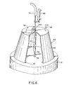
- Figure 6 illustrates an extended rod of stoppers as used in the method illustrated in Figures 5A, 5B and 5C.
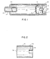
- the fluid fueled inflator illustrated in Figure 1 includes an electrically activated igniter, or squib 10, which is mounted on an end closure 11 so that, when activated, it fires hot ignition products into a fluid fuel storage chamber 12, defined in part by metal cup 13, causing the fuel to expand and rupture the chamber 12.
- the fuel and ignition products from the squib are then propelled into, and combust with, oxidizing gases provided in combustion chamber 14, producing combustion products at elevated temperature and pressure which cause a rupture disc 16 to open.
- the combustion gases then pass into compressed gas chamber 18 where they mix with, heat and cause a pressure increase of the compressed gas stored in that chamber.
- the expanded gases cause a further rupture disc 20 to open, allowing the expanded gases to pass through the diffuser 22 and exit the inflator via ports 24, from which the expanded gases can be directed to inflate an airbag cushion.
- the fuel storage chamber 12 can be loaded with a gaseous or a liquid fuel.
- the chamber 12 was provided as a die-forged metal cup 13 having a round opening in its bottom which was sized to be press fit over the squib 10. Liquid fuel was loaded to the cup through a needle inserted through the round opening. The squib was then press fit into the opening to effectively close and seal the fuel chamber. The squib and fuel chamber assembly would then be assembled to the end closure 11, which closure would then be assembled to the remainder of the inflator, usually by an inertial weld 26 applied at its periphery.
- the present invention is directed to providing a sealed fuel storage container containing a liquid fuel, such as kerosene, gasoline or methyl, ethyl or propyl alcohol, which can be either substituted for, or loaded in, cup 13.
- a liquid fuel such as kerosene, gasoline or methyl, ethyl or propyl alcohol
- the sealed storage container can also contain a liquified gaseous fuel, such as liquified propane or butane.
- the liquid fuel containing sealed unit can be prepared at a special installation designed for the safe loading of volatile, flammable liquids; and after being loaded and sealed can be stored and/or moved to and assembled into an inflator at another inflator assembly location in relative safety.
- FIG. 2 illustrates one embodiment of a liquid fuel storage container.
- the fuel container 112 is formed from metal, plastic or ceramic, in a generally cylindrical shape provided by cylindrical side wall 30.
- An igniter pocket 32 shaped so as to partially surround the igniter or squib 10, can be provided in the bottom end closure 34 of the fuel container. Such an igniter pocket 32 could extend into the container 10 to 30% of the distance D between the fill port 36 and the interior wall of the bottom end closure 34.
- the container can include designated weakened areas which will preferentially open, or rupture, when the squib is activated. It should be noted that the efficiency or completeness of combustion can be enhanced for given situations through judicious placement of the preweakened areas.
- the combustion reaction is enhanced if such weakened areas are provided in the cylindrical side wall 30 whereby the liquid fuel is directed toward the side of the combustion chamber 14.
- side discharge mechanisms work well with relatively large combustion chamber volumes. They do not work as well with extremely small combustion chambers because liquid fuel is discharged directly onto the relatively cold wall of such chambers.
- the cup 13 can be provided with pre-weakened areas complementing those provided on the fuel container.
- the top end of the fuel container is closed except for a fill port 36, which is closed with a stopper, or plug, and sealed after the storage container is filled.
- An alternative embodiment could have a neck extending upward from the fill port. Such a container could be closed and sealed either with a similar stopper or by crimping a metal cap over the neck.
- the fuel container is subject, either directly or indirectly through the metal cup 13, to the pressure of the oxidizing gas stored in the combustion chamber 14.
- the oxidizing gas can be stored at relatively high pressure, for instance 500 to 2000 psia.
- the fuel storage container design is further dependent on the fuel fill fraction to be charged thereto (the fuel fill fraction is the volumetric ratio of the liquid fuel volume to the total internal volume of the fuel storage container).
- the degree to which the fuel storage element is filled with liquid fuel i.e. the fuel fill fraction, is a parameter which can be adjusted to control the auto-ignition temperature of the inflator.
- the thermal expansion characteristics of most liquid fuels make it necessary to maintain a fraction of the internal volume of the fuel storage containers free of liquid fuel. Because the inflator and its fuel storage container must function over an extreme range of ambient temperatures (usually taken to be -40°C to 107°C), the fuel will necessarily attempt to expand and contract.
- the fuel storage container can be designed to accommodate a fill fraction selected to cause auto-ignition of the inflator at a preselected desired temperature.
- the design fill fraction will be dependent on the particular fuel, the structural characteristics of the fuel storage chamber, the maximum temperature of the ambient temperature range specified and, optionally, the desired auto-ignition temperature.
- FIG. 3 illustrates an installation for filling the liquid fuel storage containers 112.
- a conveyor belt 50 is provided to move fuel containers 112 from a first station 52 where empty storage containers 112 are loaded on the conveyor, to a second station 54 where liquid fuel is loaded in the containers 112, then to a third station 56 where a plug or ball is welded in the fill port, and finally to a fourth station 58 where the filled and sealed storage container is off loaded from the conveyor.
- the fuel containers can be loaded directly on the conveyor belt and the belt started and stopped to transfer the container from one station to the next.
- the pallet Upon reaching the next station the pallet is raised off of the running conveyor by a raising and locating device as simple as three or four pins which rise from positions just outside the running conveyor belt to engage mating structures on the bottom of the pallet.
- the pins cooperate with the pallet and the mating structures and nesting structure thereon to align the fill port on the storage container with the filling and sealing apparatus provided at the second and third stations.
- the second station 54 and the third station 56 are located under hoods 60 and 62.
- Fabric baffles (not shown) are located over the path of the conveyor as it enters and exits the hood 60 over the second station 54, and, optionally as it exits the hood 62 over the third station 56.
- the second station 54 and the third station 56 are maintained under a slight vacuum provided from an exhaust fan or other vacuum source (not shown) in order to constantly remove from the installation any potentially explosive or combustible vapors given off by the liquid fuel.
- a fill head 64 is located in place on top of the fuel container 112 where it forms a seal with a mating surface on the fuel container.
- Fill head 64 is operatively connected to a vacuum pump 66 through conduit 68.
- Fuel pump 70 provides liquid fuel from the fuel tank 72 through conduit 74 to a fuel fill needle or conduit 78 (see Figure 4) located within the fill head 64.
- a flow meter for measuring the amount of fluid fuel charged to each container is provided at any convenient location between the fuel pump and the fuel fill needle.
- a stopper insertion device is also located at the second station.
- the stopper insertion device is mounted so as to be capable of being moved into position where it can insert a plug in the fill port after the liquid fuel fill is completed.
- a welding device 80 which is capable of welding the plug to adjoining portions of the fuel container, by such as a laser or ultrasonic weld, is provided at the third station 56.
- a suitable power cable 82 connects the welding device 80 to a welding power supply apparatus 84.
- Multiple filling lines can be provided across a single conveyor and hood assembly by providing a separate fill head 64, stopper insertion device and welding device 80 for each of the filling lines.
- the fill head 64 is schematically shown in position on top of a fuel storage container 112 in Figure 4.
- the fill head 64 comprises a housing 90 having a sealing structure, such as an O-ring 92, located around the periphery of its open bottom.
- the fill head includes an operative connection to the vacuum conduit 68, to provide a vacuum which, when the O-ring seal is mated to the fuel storage container, exhausts the interior chamber of the fill head of any ambient atmosphere introduced either during the transfer operation or by leakage and removes any fuel vapors emanating from the storage chamber.
- a fill conduit, or fill needle 78 passes through a fill needle housing tube 94, which guides the needle to the fill port 36 in the top surface of the storage container 112.
- the fill needle is operatively connected to the fuel pump 70 through fuel transfer conduit 74.
- the fill needle 78 is operatively connected to a conventional raising and lowering mechanism, such as a reversible motor or, as shown, a fluid-activated, i.e. hydraulic or pneumatic activated, cylinder 96, for inserting and retracting the fill needle to and from its fill position in the storage chamber 112.
- the raising and lowering mechanism could be mounted at a convenient location either inside of the evacuated interior chamber or, as shown, on the outside of the fill head.
- a fill needle position sensing device 98 may also be provided on or about the fill head 64.
- the fill head 64 is positioned on top of the container 112 where it forms a seal with a mating surface provided on the container.
- the vacuum created by the vacuum pump 66 through conduit 68 removes any vapors, such as volatilized fuel or stray oxidant, from within the fill head.
- the fill needle is lowered into the fuel storage container 112 to an initial position near the bottom of the container, i.e. within the bottom one-fourth of the container, and, preferably, within the bottom one-tenth of the container.
- the sequence of steps can be controlled by a timed sequence of steps calibrated to provide the required conditions for the specific storage container and specific fuel fill involved.
- a more positive control can be provided by sensing the location of the fill needle within the container with a position sensing device 98.
- the sensing device determines that the needle is at its desired initial position near the bottom of the container, it provides a signal which is operative to discontinue any further lowering of the fill needle into the container.
- the sensing device 98 could function to discontinue the flow of hydraulic or pneumatic fluids to the cylinder 96.
- the sensing device could turn off a motor (not shown) which provides an alternative motive force for lowering the fill needle in the container. The flow of liquid fuel through the fill needle is then initiated.
- the fill needle is then withdrawn from the container 112, the vacuum provided through line 68 is turned off and the fill head 64 is moved away from the container.
- a push rod (not shown) may be mounted on the fill head 64 to push down on the container 112, if needed to break the seal formed between the container and the fill head.
- a stopper insertion device (such as is illustrated in Figures 5A and 5B, infra) is moved into position and activated to insert a stopper 158 in the container's fill port 36, following which the stopper insertion device is retracted.
- the storage container 112 is then moved by the conveyor 50 through a fabric curtain baffle to the third station 56 under hood 62.
- a welding head on the welding device 80 is positioned adjacent the stopper 158 inserted in the container's fill port 36 so that upon activation of the power supply 84 the stopper is welded to the adjoining portion of the fuel container.
- the welding device and associated equipment are designed to provide either a laser weld or an ultrasonic weld.
- the stopper is designed to provide a leak proof closure of the fill port. The weld of such stopper to the adjoining portion of the container provides assurance of a hermetic seal over the extended lifetime and environmental conditions under which the airbag system is expected to function.
- the filled and sealed storage container can be off-loaded from the conveyor and either conveyed directly to an inflator assembly area or packaged for storage and/or movement to the inflator assembly area.
- serial markings such as a bar-code
- An apparatus for providing such serial markings on the wall of each storage container could be provided at any convenient location along the conveyor path. We find the fourth station to be suitable for providing the apparatus for and conducting the serial marking operation.
- the filled and sealed storage container can be checked for leaks at any suitable location following the sealing of the stopper to an adjacent portion of the storage container.
- leak check should be accomplished before removing the filled storage container from a special ventilation environment such as that provided in and about the fuel filling and sealing apparatus.
- the ability to check the fuel storage container for leaks prior to assembling such in an inflator assembly provides both safety and manufacturing advantages over the prior method of loading fluid fuel in inflators as they are finally assembled.
- a fuel leak in that is only discovered after the inflator is essentially fully assembled could necessitate discarding the entire inflator assembly.
- a leak discovered in one of the present fuel storage containers prior to its fabrication into the inflator assembly should not require the discard of anything greater than the filled storage container.
- the liquid fuel filled and sealed storage container is incorporated into the assembly of an inflator, such as the inflator illustrated in Figure 1, by placing the container 112 in the metal cup 13 and inserting the squib into the igniter pocket 32 of the container 112. This sub-assembly is then assembled to the end closure 11.
- the long term reliability of the assembly of the container 112 with the squib 10 and the end closure 11 is enhanced by welding the metal cup 13 to the end closure 11.
- the container 112 provides sufficient insulation of the liquid fuel loaded therein to allow welding of the metal cup 13 to the end closure.
- the end closure is then welded to the remainder of the inflator by a peripheral weld 26.
- the filled storage container could be operatively mounted adjacent the squib by other methods which do not rely on metal cup 13.
- the igniter pocket and the squib could be provided with complementary locking shapes, possibly augmented by an interlocking pin or plunger, whereby the storage container is firmly mounted to the squib.
- the quantity of liquid fuel charged to the container could be controlled by techniques other than the described method of monitoring a flow meter.
- the liquid fuel could be passed from the fuel tank to an intermediate chamber designed to accept only, or otherwise measure, the precise quantity of fuel to be charged to each storage container and then transferring such measured quantity to each storage chamber.
- Figures 5A, 5B and 5C illustrate a particularly advantageous, and heretofore novel, method of sealing the fuel storage containers.
- Figures 5B and 5C illustrate subsequent operations occurring at the fuel storage container's fill port located within the circle "C" of each of the figures. Since the fill port is very small, typically in the range of 1mm to 10mm in diameter, and the stopper is likewise very small, the manipulation and insertion of the miniature stopper can be difficult to accomplish manually or with most high speed automated assembly equipment.
- a rod-like structure 150 of multiple stoppers arranged end-to-end is fed from a roll, or reel 151, into and through a guide tube 152 which can be controlled to direct the lead stopper 154, at the end of the rod, into the fill port 36 of the filled storage chamber 112.
- the reel of rod-like structures and the guide tube are mounted at the second station 54 so as to be moveable from a first position where they are out of the way of the fill head 64 as it is operatively connected to the fuel storage container 112, to a second position where the reel and guide tube are in position to seal the fill port 36 of the filled fuel storage container 112.
- Each stopper has a body portion at its leading end having a diameter b (see Figure 6) essentially equal to the diameter of the fill port 36 and a rim portion at its following end having a diameter c ( Figure 6) which is larger than the diameter of the fill port.
- the leading end of the stopper is forced into the fill port until the rim of the stopper abuts the storage container adjacent the fill port.
- a cutting device 156 ( Figure 5B) then cuts the head of the inserted stopper 158 free of the next stopper 160 on the rod.
- the fill tube containing the rod of stoppers is then moved away from the fuel storage container.
- the fuel storage container 112 is then moved to the third station 56 where an ultrasonic or laser welding device 80 ( Figure 5C) is positioned adjacent the stopper and activated to permanently seal the rim of the stopper 158 to the adjoining portion of the container 112.
- each stopper has a length a, which is about 2mm to about 10mm, and, at its lead end, has a body portion having a diameter b which is the same as, or, preferably, slightly larger than the diameter of the fill port 36.
- the diameter b of the body portion of the stopper is about lmm to about 10mm and, preferably, about 2mm to about 5mm.
- Each stopper has, at its following end, a rim portion having a diameter c which is about 2mm to about 5mm larger than the diameter of the body portion.
- the rod-like structure of stoppers can be made of metal, such as stainless steel; plastic, such as polyolefin; or ceramic. It can be produced by well known techniques, such as molding or impact processing.
- the stoppers preferably are made of a material which is similar to, but harder than, the material of the storage container in which they are to be inserted.
- the plurality of stoppers form a rod which can be stored in, and fed from, a rolled condition
- the structure be sufficiently flexible to permit such a rolled form.
- Relatively inflexible rod-like structures can be stored and fed to the fill tube as essentially straight rods.
- stoppers of relatively inflexible material can be fed as a plurality of individual stoppers arranged end-to-end and held in place by an encircling tube, which tube is shrunk around the plurality of individual stoppers by well known vacuum-sealing or shrink-fitting processes, to result in an extended structure which has sufficient stiffness to maintain itself in a rod-like form and yet is sufficiently flexible to be stored in, and fed from, a rolled form.
- the use of similar metal and plastic materials to fabricate both the storage container and the stopper is preferred because it is easier to weld similar materials.
- the bonding of the stopper to the storage container can be enhanced by providing an adhesive, sealing or other bonding material between the stopper and the storage container. Such a bonding material could be applied during assembly to either the rod-like structure or to the fill port.
- the leading end of the stopper can be provided with a tapered or beveled surface to assist its insertion into the fill port.
- the three operations of liquid fuel filling, stopper insertion and welding are accomplished at two stations. These operations can, however, be conducted at one, two or three individual stations.
- the fuel containers can be conveyed from station to station by any suitable known type of conveyer, such as the belt conveyer shown in Figure 3, a rotary conveyor or a dial table.
Landscapes
- Physics & Mathematics (AREA)
- Fluid Mechanics (AREA)
- Engineering & Computer Science (AREA)
- Mechanical Engineering (AREA)
- Air Bags (AREA)
- Loading And Unloading Of Fuel Tanks Or Ships (AREA)
- Cooling, Air Intake And Gas Exhaust, And Fuel Tank Arrangements In Propulsion Units (AREA)
- Filling Or Discharging Of Gas Storage Vessels (AREA)
Applications Claiming Priority (2)
| Application Number | Priority Date | Filing Date | Title |
|---|---|---|---|
| US716123 | 1996-09-19 | ||
| US08/716,123 US5787685A (en) | 1996-09-19 | 1996-09-19 | Process and apparatus for filling liquid fuel storage containers and assembling such containers into fluid fueled airbag inflators |
Publications (1)
| Publication Number | Publication Date |
|---|---|
| EP0830992A2 true EP0830992A2 (de) | 1998-03-25 |
Family
ID=24876852
Family Applications (1)
| Application Number | Title | Priority Date | Filing Date |
|---|---|---|---|
| EP97307055A Withdrawn EP0830992A2 (de) | 1996-09-19 | 1997-09-11 | Verfahren und Vorrichtung zum Füllen von Vorratsbehältern mit flüssigem Brennstoff und Zusammensetzen solcher Behälter in Luftsack- Gasgeneratoren mit flüssigemBrennstoff |
Country Status (3)
| Country | Link |
|---|---|
| US (1) | US5787685A (de) |
| EP (1) | EP0830992A2 (de) |
| JP (1) | JP3946831B2 (de) |
Families Citing this family (5)
| Publication number | Priority date | Publication date | Assignee | Title |
|---|---|---|---|---|
| US7565795B1 (en) * | 2006-01-17 | 2009-07-28 | Pratt & Whitney Rocketdyne, Inc. | Piezo-resonance igniter and ignition method for propellant liquid rocket engine |
| US20080299504A1 (en) * | 2007-06-01 | 2008-12-04 | Mark David Horn | Resonance driven glow plug torch igniter and ignition method |
| FR2928517B1 (fr) * | 2008-03-11 | 2011-10-07 | Imagene | Procede industriel d'encapsulation de materiel biologique en vue d'une conservation a temperature ambiante |
| US8814562B2 (en) * | 2008-06-02 | 2014-08-26 | Aerojet Rocketdyne Of De, Inc. | Igniter/thruster with catalytic decomposition chamber |
| US8161725B2 (en) * | 2008-09-22 | 2012-04-24 | Pratt & Whitney Rocketdyne, Inc. | Compact cyclone combustion torch igniter |
Family Cites Families (14)
| Publication number | Priority date | Publication date | Assignee | Title |
|---|---|---|---|---|
| US3070137A (en) * | 1959-04-06 | 1962-12-25 | Thiokol Chemical Corp | Device for filling containers with liquids |
| US3040787A (en) * | 1959-04-30 | 1962-06-26 | Fmc Corp | Bottom filling nozzle |
| US3056436A (en) * | 1959-06-24 | 1962-10-02 | Cherry Burrell Corp | Filling head for filling machines |
| US3559702A (en) * | 1968-01-24 | 1971-02-02 | Consolidated Packaging Machine | Container filling machine |
| US4957147A (en) * | 1987-10-01 | 1990-09-18 | Lowe Terry B | Container filling apparatus |
| US4932445A (en) * | 1988-06-27 | 1990-06-12 | Biehl Bruce D | Subsurface filler |
| US5193593A (en) * | 1990-08-13 | 1993-03-16 | Colgate-Palmolive Company | Package filling method and apparatus |
| US5196669A (en) * | 1991-11-12 | 1993-03-23 | Rwc, Inc. | Methods and apparatus for supplying gas under high pressure to weldable air bag vessels with a gas passage formed therein, and like products, and then weld-sealing the passage |
| US5424509A (en) * | 1993-10-28 | 1995-06-13 | Morton International, Inc. | Method and apparatus for welding shut a gas passage in vessels |
| US5494312A (en) * | 1994-05-31 | 1996-02-27 | Morton International, Inc. | Autoignition of a fluid fueled inflator |
| US5470104A (en) * | 1994-05-31 | 1995-11-28 | Morton International, Inc. | Fluid fueled air bag inflator |
| US5531473A (en) * | 1994-05-31 | 1996-07-02 | Morton International, Inc. | Fluid fuel-containing initiator device for an air bag inflator |
| US5551493A (en) * | 1994-08-05 | 1996-09-03 | Reagent Chemical & Research, Inc. | Filling apparatus with traveling nozzle |
| US5495699A (en) * | 1994-11-09 | 1996-03-05 | Weldun International, Inc. | Method and apparatus for pressure filling and sealing a vessel |
-
1996
- 1996-09-19 US US08/716,123 patent/US5787685A/en not_active Expired - Fee Related
-
1997
- 1997-09-11 EP EP97307055A patent/EP0830992A2/de not_active Withdrawn
- 1997-09-19 JP JP25471797A patent/JP3946831B2/ja not_active Expired - Fee Related
Also Published As
| Publication number | Publication date |
|---|---|
| JP3946831B2 (ja) | 2007-07-18 |
| US5787685A (en) | 1998-08-04 |
| JPH10100852A (ja) | 1998-04-21 |
Similar Documents
| Publication | Publication Date | Title |
|---|---|---|
| US5673933A (en) | Canister assembled fluid fueled inflator | |
| EP1019269B1 (de) | Druckflüssigkeit enthaltende luftsack-aufblasvorrichtung | |
| KR0184040B1 (ko) | 에어 백 팽창 장치와 그 팽창 장치의 제조 방법 | |
| US5348344A (en) | Apparatus for inflating a vehicle occupant restraint using a mixture of gases | |
| US6553914B2 (en) | Gas generator | |
| KR100190891B1 (ko) | 에어백 팽창용 장치 및 그 제조방법 | |
| EP0918666B1 (de) | Aufblasvorrichtung mit zentraler gasfüllung | |
| US5787685A (en) | Process and apparatus for filling liquid fuel storage containers and assembling such containers into fluid fueled airbag inflators | |
| US5577769A (en) | Hybrid inflator for inflating air bags | |
| WO1997048581A1 (en) | Inflator for vehicle air bags | |
| JP3049461U (ja) | 車両用安全拘束装置のインフレータ | |
| US6557890B1 (en) | Hybrid-type device for inflating vehicle safety equipment | |
| US5673731A (en) | Method and apparatus for filling elongated pressurized fluid containers from the side | |
| US5924728A (en) | Fuel bottle attachment in fluid fueled inflator | |
| US5964479A (en) | Acetylene-based airbag inflator | |
| US6221186B1 (en) | Self-compensating airbag inflator and method | |
| US6286864B1 (en) | Ultra low cost inflator device and method of manufacturing such | |
| EP1598244B1 (de) | Verfahren zur Herstellung eines Gasgenerators | |
| USRE37843E1 (en) | Apparatus for inflating a vehicle occupant restraint using a mixture of gases | |
| US5424509A (en) | Method and apparatus for welding shut a gas passage in vessels | |
| US8037905B2 (en) | Gas fill process and inflator weld design simplification | |
| CN1972825A (zh) | 压力波气体发生器 | |
| EP0921966B1 (de) | Hybride aufblasvorrichtung zum aufblasen von airbags |
Legal Events
| Date | Code | Title | Description |
|---|---|---|---|
| PUAI | Public reference made under article 153(3) epc to a published international application that has entered the european phase |
Free format text: ORIGINAL CODE: 0009012 |
|
| AK | Designated contracting states |
Kind code of ref document: A2 Designated state(s): AT BE CH DE DK ES FI FR GB GR IE IT LI LU MC NL PT SE |
|
| AX | Request for extension of the european patent |
Free format text: AL;LT;LV;RO;SI |
|
| STAA | Information on the status of an ep patent application or granted ep patent |
Free format text: STATUS: THE APPLICATION HAS BEEN WITHDRAWN |
|
| 18W | Application withdrawn |
Withdrawal date: 19980504 |