EP0830914B1 - Method of and apparatus for controlling welding conditions of a resistance welder - Google Patents
Method of and apparatus for controlling welding conditions of a resistance welder Download PDFInfo
- Publication number
- EP0830914B1 EP0830914B1 EP97116380A EP97116380A EP0830914B1 EP 0830914 B1 EP0830914 B1 EP 0830914B1 EP 97116380 A EP97116380 A EP 97116380A EP 97116380 A EP97116380 A EP 97116380A EP 0830914 B1 EP0830914 B1 EP 0830914B1
- Authority
- EP
- European Patent Office
- Prior art keywords
- welding
- detected
- monitor value
- status quantity
- change
- Prior art date
- Legal status (The legal status is an assumption and is not a legal conclusion. Google has not performed a legal analysis and makes no representation as to the accuracy of the status listed.)
- Expired - Lifetime
Links
Images


Classifications
-
- B—PERFORMING OPERATIONS; TRANSPORTING
- B23—MACHINE TOOLS; METAL-WORKING NOT OTHERWISE PROVIDED FOR
- B23K—SOLDERING OR UNSOLDERING; WELDING; CLADDING OR PLATING BY SOLDERING OR WELDING; CUTTING BY APPLYING HEAT LOCALLY, e.g. FLAME CUTTING; WORKING BY LASER BEAM
- B23K11/00—Resistance welding; Severing by resistance heating
- B23K11/24—Electric supply or control circuits therefor
- B23K11/25—Monitoring devices
- B23K11/252—Monitoring devices using digital means
- B23K11/257—Monitoring devices using digital means the measured parameter being an electrical current
-
- B—PERFORMING OPERATIONS; TRANSPORTING
- B23—MACHINE TOOLS; METAL-WORKING NOT OTHERWISE PROVIDED FOR
- B23K—SOLDERING OR UNSOLDERING; WELDING; CLADDING OR PLATING BY SOLDERING OR WELDING; CUTTING BY APPLYING HEAT LOCALLY, e.g. FLAME CUTTING; WORKING BY LASER BEAM
- B23K11/00—Resistance welding; Severing by resistance heating
- B23K11/24—Electric supply or control circuits therefor
- B23K11/25—Monitoring devices
- B23K11/252—Monitoring devices using digital means
- B23K11/258—Monitoring devices using digital means the measured parameter being a voltage
Definitions
- the present invention relates to a method of and an apparatus for controlling welding conditions according to the preambles of claim 1 and claim 10, respectively, and as known from Patent Abstracts of Japan, vol. 95, no. 10, 30 November 1995.
- Resistance welding particularly spot welding is used for various products using steel plates, but it has a tendency of increasing welding failures recently. That is, soft steel plates have been generally used as material to be welded conventionally, so that there has been few failure in conducting, and the quality of welding has been able to be kept comparatively stable if the welding conditions are controlled to be constant. However, galvanized steel plates or high-tensile steel plates have come to be used instead of soft steel plates, so that welding failures have become increased. Therefore, an apparatus which can not only monitor the welding conditions in a simple manner but also control the quality of welding accurately in needed.
- the method 1) it is difficult to judge the quality of resultant welding because the change pattern of resistance is not uniform when crushing of the head portion of a chip or a split current is produced, or when the material to be welded is a galvanized steel.
- the method 2) it is difficult to judge the quality accurately in practical use because the judgement conditions of resultant welding must be set whenever a change occurs in welding conditions such as crushing of a chip, change of thickness, and so on.
- the methods 3) and 4) have problems that the methods cannot be applied to working in the site with respect to installation and attachment of temperature detection means and ultrasonic wave transmitting and receiving means.
- the method 5) has practical problems caused by inclusion of noise, difficulty in measurement of a very small displacement, individual differences in mechanical strength of resistance welders, and so on, when the method is applied to working in the welding site.
- the method 6) can be realized at a low price and easily and is useful in detecting fault of a power supply, breaking of a secondary conductor, and so on, it is impossible to judge the quality of a welding portion deteriorated by the reduction of electric current density caused by crushing of the head portion of a chip, production of a split current, and so on.
- the method 7 has a possibility to solve the foregoing problem, but has a weakest point in that it takes much time to solve an equation of heat conduction. Therefore, a measure to calculate a nugget diameter at a high speed has been developed, and an apparatus for monitoring all the welding points in the welding site after finishing welding has been put into practice.
- the method 8 takes a step forward than the method 7), but it merely corrects the temperature distribution and does not take into consideration the existence of interface resistance between an electrode and a plate due to electrode abrasion which gives a large influence onto the estimation of temperature distribution of a welding portion. Accordingly, in the method 8), it is difficult to estimate the temperature distribution accurately.
- Patent Abstracts of Japan, vol. 95, no. 10, 30 November 1995 - & JP 07 185835 A discloses a method for obtaining information for setting the welding conditions by an operator, for example.
- the voltage between electrodes is measured by using a voltage detecting wire mounted to welding electrodes.
- An arithmetic part estimates the temperature distribution of a member to be welded and of the welding electrodes at each unit time.
- the naked diameter is estimated by the temperature distribution and the forming time is estimated where the estimated naked diameter exceeds the set naked diameter.
- the present invention is achieved to solve the foregoing conventional problems, and it is an object of the invention to provide a method of controlling welding conditions of a resistance welder, in which the state that a nugget is generated can be estimated with general-purpose properties, and in which an accurate and high-quality resultant welding can be obtained.
- the apparatus further comprises:
- a method of controlling welding condition of a resistance welder according to the present invention is characterized by the further following steps :
- the reference numeral 1 represents a condition setting portion for setting dimensions of a welding portion in advance; 2, a signal processing portion supplied with a welding current and a welding voltage for performing signal processing upon the values of the current and voltage; 3, a magnetic permeability change detection portion; 4, a heat conduction simulator for simulating the welding portion on the basis of heat conduction calculation; 5, a comparison portion for estimating the time when the welding portion is fused on the basis of the time when magnetic permeability is detected, and comparing the estimated value with the fusing time estimated by the heat conduction simulator 4; 6, a control portion for controlling a welding power supply; 7, a welding power supply; 8, a welding electrode; 9, a welding current detection portion; 10, a tip-to-tip voltage detection cable; and 11, a material to be welded.
- welding is started after, of various factors of welding conditions, various dimensions which are not objects to be controlled, that is, the quality and thickness of the material to be welded, the shape of the electrode chip, and so on, are supplied from the condition setting portion 1.
- Values of a welding current, a welding voltage, and so on, which are objects to be controlled are supplied into the signal processing portion 2 continuously, and on the basis of an impedance change of the material to be welded which is obtained by dividing an instantaneous value of the welding voltage by an instantaneous value of the welding current, it is confirmed by the magnetic permeability change detection portion 3 whether the temperature of the material to be welded, which is a magnetic material, increases to be equal to or more than the magnetic transformation temperature (Curie temperature) to thereby produce a magnetic permeability change so that an inductance component is reduced suddenly or not (Fig. 2).
- the measured values of the welding current and welding voltage are supplied into the heat conduction simulator 4.
- material constants such as a fringing coefficient taking into consideration a specific resistance value or the way of flow of an electric current in a portion upon which a numerical operation will be performed are determined.
- the above-mentioned measured values of the welding current and welding voltage are inputted into a difference equation made up with the determined material constants so as to perform a numerical operation to thereby calculate current density and conducting diameter in every grid.
- a temperature equation made up with material constants such as specific heat, heat conductivity and so on and the above-mentioned conducting diameter is solved to thereby calculate temperature distribution in every grid.
- the area where the temperature is beyond the fusing temperature in the calculated temperature distribution is regarded as a nugget.
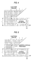
- a third step an interface resistance is inserted by use of the calculated temperature distribution in every lattice (Fig. 5), or the fringing coefficient is corrected.
- the first to third steps are repeated until the current conduction is ended.
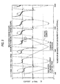
- Fig. 3 is a waveform diagram where a change in the magnetic permeability is estimated from a change in the impedance in a nugget portion during welding. As a result, a change in the inclination of impedance near a peak of the welding current can be detected and determined by the magnetic permeability changing time.
- the fusing time estimated from this magnetic permeability changing time and the fusing time of the center portion estimated by the heat conduction simulator 4 are compared in the comparison portion 5.
- the configuration and the numerical value to be used by the simulator are left as it is.
- at least one of the configuration and the numerical value to be used by the simulator is modified to make the output result of the simulator coincide with the physical phenomenon (welding phenomenon).
- an interface resistance as a constituent which is not included in the heat conduction simulator 4 is inserted to the interface between the electrode and the material to be welded when the configuration is changed.
- Fig. 4 shows the basic configuration of the heat conduction simulator 4 before changed, while Fig.
- FIG. 5 shows the configuration of the heat conduction simulator 4 which has been changed.
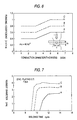
- a flinging coefficient ( ⁇ c/ ⁇ o) defining the way of flow of the welding current in the material to be welded is changed on the simulator.
- Fig. 7 shows values A, B and C of the fringing coefficient ( ⁇ c/ ⁇ o) to be changed and the variations of the production state of nugget diameters A, B and C estimated by the simulator as a result. Since the heat conduction simulator 4 is corrected with reference to a real welding phenomenon, it is possible to estimate the process of temperature increase of the welding portion accurately, and it is possible to control the welding conditions to produce the welding portion in a predetermined time and with a nugget having a sufficient diameter.
- the welding condition to be controlled was a welding current in this embodiment, any other welding condition, that is, at least one of electrode welding pressure and welding time may be changed.
- any other physical phenomenon accompanied by the welding phenomenon may be used in the same way as this embodiment. That is, the time when the welding portion in the material to be welded reaches a desired fusing diameter (nugget diameter) can be estimated from the welding pressure of the welding electrode and the quantity of movement of the electrode. In addition, if production of expulsion is detected during welding, it can be confirmed that the temperature of the center portion has reached the fusing temperature, or the behavior of the welding portion can be also estimated by the sound of welding generated during welding.
- the temperature of the welding portion can be estimated from the surface temperature of the material to be welded, or the time of production of the welding portion can be estimated from the detection of a magnetic transformation point (Curie temperature) of the welding portion based on the magnetic detection of the welding portion. Further, if an ultrasonic wave is applied to the welding portion, it is possible to detect the time of production of the welding portion. In such a manner, other physical monitor values accompanied by the welding phenomenon may be used for the heat conduction simulator in the same manner.
- the production state of a nugget can be monitored during welding with general-purpose properties, and the welding conditions can be changed in accordance with the monitored state so as to produce a predetermined nugget diameter accurately.
- the invention provides a superior welding effect to obtain an accurate and high-quality resultant welding.
Landscapes
- Engineering & Computer Science (AREA)
- Mechanical Engineering (AREA)
- Resistance Welding (AREA)
- Management, Administration, Business Operations System, And Electronic Commerce (AREA)
- Investigating Or Analyzing Materials By The Use Of Electric Means (AREA)
Description
- The present invention relates to a method of and an apparatus for controlling welding conditions according to the preambles of
claim 1 andclaim 10, respectively, and as known from Patent Abstracts of Japan, vol. 95, no. 10, 30 November 1995. - Resistance welding, particularly spot welding is used for various products using steel plates, but it has a tendency of increasing welding failures recently. That is, soft steel plates have been generally used as material to be welded conventionally, so that there has been few failure in conducting, and the quality of welding has been able to be kept comparatively stable if the welding conditions are controlled to be constant. However, galvanized steel plates or high-tensile steel plates have come to be used instead of soft steel plates, so that welding failures have become increased. Therefore, an apparatus which can not only monitor the welding conditions in a simple manner but also control the quality of welding accurately in needed.
- To solve this problem, as a technique which is not a device for controlling a welder directly but which is similar thereto, various welding quality monitoring apparatuses have been developed in order to judge the quality of resultant welding after the welding is finished. If the quality of welding can be judged, the result can be reflected on the succeeding welding. For example, the following methods and so on have been developed:
- 1) A method in which tip-to-tip resistance is obtained from a welding current and a welding voltage, the quality of resultant welding is judged from a change pattern of the tip-to-tip resistance, for example, as disclosed in Japanese Patent Unexamined Publication No. Sho-56-158286;
- 2) A method in which tip-to-tip voltage is compared with a variation with time of a predetermined reference voltage, and the quality of resultant welding is judged by the fact as to whether the difference therebetween is within an allowable range, for example, as disclosed in Japanese Patent Unexamined Publication No. Sho-59-14312, and another method in which an active component effectively contributing to heat generation of a welding portion is extracted from a tip-to-tip voltage, and the quality of resultant welding is judged from a time quadrature value of the active component, for example, as disclosed in Japanese Patent Unexamined Publication No. Sho-59-40550 or No. Sho-59-61580;
- 3) A method in which heat generation temperature is detected, and the quality of resultant welding is judged from a temperature change pattern, for example, as disclosed in Japanese Patent Unexamined-Publication No. Hei-1-216246;
- 4) A method in which an ultrasonic wave is made to penetrate material to be welded, and the quality of resultant welding is judged from the penetrating quantity, for example, as disclosed in Japanese Patent Unexamined Publication No. Sho-52-94841;
- 5) A method in which a displacement of an electrode chip during welding is used, for example, as disclosed in Japanese Patent Unexamined Publication No. Sho-60-40955;
- 6) A method in which a welding current is detected, and its upper and lower limit values are monitored so as to make the resultant welding constant; and
- 7) A method in which a heat-conduction model is used, and a nugget diameter is calculated by using a computer, for example, as disclosed in Paper by Sano, "Research on Numerical Analysis of Conducting Path and Temperature Distribution in Spot Welding", Osaka University Postgraduate Course Welding Subject Master's Thesis (1979), and Paper by Nishiu "Research on Speeding-up Monitoring of Quality for Helping Calculation of Numerical Values for Resistance Spot Welding", Osaka University Postgraduate Course Welding Subject Master's Thesis (1991).
-
- In addition, there is a method for controlling a welder directly, as follows:
- 8) A method in which base material temperature distribution is calculated from a heat-conduction model, and a nugget diameter is estimated from the temperature distribution while the temperature distribution is corrected by using the quantity of movement of an electrode during welding, as disclosed in Japanese Patent Unexamined Publication no. Hei-7-16791.
-
- Of these conventional methods, in the method 1) it is difficult to judge the quality of resultant welding because the change pattern of resistance is not uniform when crushing of the head portion of a chip or a split current is produced, or when the material to be welded is a galvanized steel. In the method 2), it is difficult to judge the quality accurately in practical use because the judgement conditions of resultant welding must be set whenever a change occurs in welding conditions such as crushing of a chip, change of thickness, and so on. The methods 3) and 4) have problems that the methods cannot be applied to working in the site with respect to installation and attachment of temperature detection means and ultrasonic wave transmitting and receiving means. The method 5) has practical problems caused by inclusion of noise, difficulty in measurement of a very small displacement, individual differences in mechanical strength of resistance welders, and so on, when the method is applied to working in the welding site. Although the method 6) can be realized at a low price and easily and is useful in detecting fault of a power supply, breaking of a secondary conductor, and so on, it is impossible to judge the quality of a welding portion deteriorated by the reduction of electric current density caused by crushing of the head portion of a chip, production of a split current, and so on.
- Working to perform a preliminary experiment in the welding site upon every welding material so as to obtain the relationship between the quality of welding and the standard of judgement in advance is inevitable in these conventional welding quality monitoring apparatuses, and as the result of the judgement, it is possible merely to judge the quality of a welding portion roughly. The method 7) has a possibility to solve the foregoing problem, but has a weakest point in that it takes much time to solve an equation of heat conduction. Therefore, a measure to calculate a nugget diameter at a high speed has been developed, and an apparatus for monitoring all the welding points in the welding site after finishing welding has been put into practice.
- Therefore, even if a conventional welding quality monitoring apparatus except those according to the methods 7) and 8) is used with a resistance welder, failure in quality is produced in a welding portion. Accordingly, not only adjustment has been required, but also there has been a risk that products are made waste or causes troubles in the market, as the case may be. In addition, even according to the method 7), it is after finishing welding that the resultant welding can be judged, and the output of the welder itself cannot be controlled to improve the resultant welding. Further, although the method 8) takes a step forward than the method 7), but it merely corrects the temperature distribution and does not take into consideration the existence of interface resistance between an electrode and a plate due to electrode abrasion which gives a large influence onto the estimation of temperature distribution of a welding portion. Accordingly, in the method 8), it is difficult to estimate the temperature distribution accurately.
- Above mentioned Patent Abstracts of Japan, vol. 95, no. 10, 30 November 1995 - & JP 07 185835 A (MATSUSHITA ELECTRIC IND CO LTD), 25 July 1995 discloses a method for obtaining information for setting the welding conditions by an operator, for example. The voltage between electrodes is measured by using a voltage detecting wire mounted to welding electrodes. An arithmetic part estimates the temperature distribution of a member to be welded and of the welding electrodes at each unit time. Additionally, the naked diameter is estimated by the temperature distribution and the forming time is estimated where the estimated naked diameter exceeds the set naked diameter.
- The present invention is achieved to solve the foregoing conventional problems, and it is an object of the invention to provide a method of controlling welding conditions of a resistance welder, in which the state that a nugget is generated can be estimated with general-purpose properties, and in which an accurate and high-quality resultant welding can be obtained.
- This object is attained, according to the present invention by a method of and an apparatus for controlling welding conditions of a resistance welder according to the features defined in the characterising portions of
claims - (c) means for comparing, when a change of said monitor value during welding process has been detected, said status quantity with a reference status quantity at the time of estimation, said reference status being determined on the basis of said monitor value
- (d) means for modifying, when a change of said monitor value during welding process has been detected and when the said status quantity and said reference status quantity are different, at least one of configuration and numerical value of said heat conduction simulator so as to make said status quantity coincide with said reference status quantity, and
- (e) means for correcting the welding conditions on the basis of the result of comparison.
-
- With the above mentioned configuration, a method of controlling welding condition of a resistance welder according to the present invention is characterized by the further following steps :
- (a) when a change of set monitor value during the welding process has been detected, estimating a status quantity expressing a not yet-forming state during welding in said welding portion and comparing said status quantity with a reference status quantity at the time of estimation and when the said status quantity and said reference status quantity are different, modifying at least one of configuration and numerical value of said heat conductor simulator so as to make said status quantity coincide with said reference quantity,
- (b) correcting the welding conditions on the basis of the result of the comparison.
-
- Accordingly, it is possible to always perform simulation of the welding portion with a high accuracy, and it is possible to realize controlling the welding conditions of a resistance welder more accurately.
-
- Fig. 1 is a block diagram illustrating an embodiment for carrying out a welding condition control method of a resistance welder according to the present invention.
- Fig. 2 is a flow chart illustrating the welding condition control method of the same resistance welder.
- Fig. 3 is a waveform diagram showing a welding current and an impedance when a change in magnetic permeability is estimated from a change in the impedance of a nugget during welding in the resistance welder.
- Fig. 4 is a calculation lattice diagram illustrating the configuration of a heat conduction simulator.
- Fig. 5 is a calculation lattice diagram illustrating the state where the configuration of the heat conduction simulator is modified.
- Fig. 6 is a characteristic diagram of a flinging coefficient when the flinging coefficient is changed.
- Fig. 7 is a characteristic diagram of production of a nugget estimated by the heat conduction simulator when the flinging coefficient is changed.
-
- An embodiment for carrying out the method of controlling welding conditions of a resistance welder according to the present invention will be described with reference to Figs. 1 to 7.
- In Fig. 1, the
reference numeral 1 represents a condition setting portion for setting dimensions of a welding portion in advance; 2, a signal processing portion supplied with a welding current and a welding voltage for performing signal processing upon the values of the current and voltage; 3, a magnetic permeability change detection portion; 4, a heat conduction simulator for simulating the welding portion on the basis of heat conduction calculation; 5, a comparison portion for estimating the time when the welding portion is fused on the basis of the time when magnetic permeability is detected, and comparing the estimated value with the fusing time estimated by theheat conduction simulator 4; 6, a control portion for controlling a welding power supply; 7, a welding power supply; 8, a welding electrode; 9, a welding current detection portion; 10, a tip-to-tip voltage detection cable; and 11, a material to be welded. - Next, the process of control on the welding conditions will be described with reference to the flow chart in Fig. 2.
- First, welding is started after, of various factors of welding conditions, various dimensions which are not objects to be controlled, that is, the quality and thickness of the material to be welded, the shape of the electrode chip, and so on, are supplied from the
condition setting portion 1. Values of a welding current, a welding voltage, and so on, which are objects to be controlled are supplied into thesignal processing portion 2 continuously, and on the basis of an impedance change of the material to be welded which is obtained by dividing an instantaneous value of the welding voltage by an instantaneous value of the welding current, it is confirmed by the magnetic permeabilitychange detection portion 3 whether the temperature of the material to be welded, which is a magnetic material, increases to be equal to or more than the magnetic transformation temperature (Curie temperature) to thereby produce a magnetic permeability change so that an inductance component is reduced suddenly or not (Fig. 2). At the same time, the measured values of the welding current and welding voltage are supplied into theheat conduction simulator 4. - Now, the operation of this
heat conduction simulator 4 will be described below. Numerical operation is performed upon grids dividing the material 11 to be welded and thewelding electrode 8 lengthwise and widthwise, every unit time(Fig. 4). - In a first step, material constants such as a fringing coefficient taking into consideration a specific resistance value or the way of flow of an electric current in a portion upon which a numerical operation will be performed are determined. The above-mentioned measured values of the welding current and welding voltage are inputted into a difference equation made up with the determined material constants so as to perform a numerical operation to thereby calculate current density and conducting diameter in every grid.
- In a second step, a temperature equation made up with material constants such as specific heat, heat conductivity and so on and the above-mentioned conducting diameter is solved to thereby calculate temperature distribution in every grid. The area where the temperature is beyond the fusing temperature in the calculated temperature distribution is regarded as a nugget.
- In a third step, an interface resistance is inserted by use of the calculated temperature distribution in every lattice (Fig. 5), or the fringing coefficient is corrected. The first to third steps are repeated until the current conduction is ended.
- When a change in magnetic permeability is confirmed by the magnetic permeability
change detection portion 3, the time from start of welding till generation of the change in the magnetic permeability, that is, till the center portion of the material to be welding reaches about 700°C is found, and further the time till the material to be welded will have been fused can be estimated. Fig. 3 is a waveform diagram where a change in the magnetic permeability is estimated from a change in the impedance in a nugget portion during welding. As a result, a change in the inclination of impedance near a peak of the welding current can be detected and determined by the magnetic permeability changing time. Further, the fusing time estimated from this magnetic permeability changing time and the fusing time of the center portion estimated by theheat conduction simulator 4 are compared in thecomparison portion 5. When there is no difference between the both, the configuration and the numerical value to be used by the simulator are left as it is. When there is any difference, at least one of the configuration and the numerical value to be used by the simulator is modified to make the output result of the simulator coincide with the physical phenomenon (welding phenomenon). In this embodiment, an interface resistance as a constituent which is not included in theheat conduction simulator 4 is inserted to the interface between the electrode and the material to be welded when the configuration is changed. In this case, Fig. 4 shows the basic configuration of theheat conduction simulator 4 before changed, while Fig. 5 shows the configuration of theheat conduction simulator 4 which has been changed. On the other hand, when the numerical value to be used is changed, a flinging coefficient (δc/δo) defining the way of flow of the welding current in the material to be welded is changed on the simulator. Fig. 7 shows values A, B and C of the fringing coefficient (δc/δo) to be changed and the variations of the production state of nugget diameters A, B and C estimated by the simulator as a result. Since theheat conduction simulator 4 is corrected with reference to a real welding phenomenon, it is possible to estimate the process of temperature increase of the welding portion accurately, and it is possible to control the welding conditions to produce the welding portion in a predetermined time and with a nugget having a sufficient diameter. Although the welding condition to be controlled was a welding current in this embodiment, any other welding condition, that is, at least one of electrode welding pressure and welding time may be changed. - Although at least one of the configuration and the numerical value to be used in the heat conduction simulator was changed with reference to the production state of a physical phenomenon (welding phenomenon) based on the detection of a change in magnetic permeability of the material to be welded in this embodiment, any other physical phenomenon accompanied by the welding phenomenon may be used in the same way as this embodiment. That is, the time when the welding portion in the material to be welded reaches a desired fusing diameter (nugget diameter) can be estimated from the welding pressure of the welding electrode and the quantity of movement of the electrode. In addition, if production of expulsion is detected during welding, it can be confirmed that the temperature of the center portion has reached the fusing temperature, or the behavior of the welding portion can be also estimated by the sound of welding generated during welding. Further, the temperature of the welding portion can be estimated from the surface temperature of the material to be welded, or the time of production of the welding portion can be estimated from the detection of a magnetic transformation point (Curie temperature) of the welding portion based on the magnetic detection of the welding portion. Further, if an ultrasonic wave is applied to the welding portion, it is possible to detect the time of production of the welding portion. In such a manner, other physical monitor values accompanied by the welding phenomenon may be used for the heat conduction simulator in the same manner.
- As it has been described above, according to the method of controlling welding condition of a resistance welder according to the present invention, the production state of a nugget can be monitored during welding with general-purpose properties, and the welding conditions can be changed in accordance with the monitored state so as to produce a predetermined nugget diameter accurately. Further, even if external factors are changed by wastage of a welding electrode or the like, an observable physical phenomenon is used as a monitor value expressing the welding state, and the calculation result of a heat conduction simulator monitoring the production state of a nugget in a welding portion is compared with the above-mentioned monitor value, so that by modifying the configuration of the heat conduction simulator, or correcting a numerical value to be used in the heat conduction simulator, it is possible to always use a high-accuracy heat conduction simulator. Accordingly, the invention provides a superior welding effect to obtain an accurate and high-quality resultant welding.
Claims (10)
- Method of controlling welding conditions of a resistance welder, comprising the steps of:characterized by(a) detecting a welding current, a tip-to-tip voltage and a monitor value, which is able to express physical phenomenon changes due to the progress of the welding process,(b) using a heat conduction simulator (4) for performing simulation of a welding portion of the basis of heat conduction calculation from the welding current and the tip-to-tip voltage,(c) when a change of set monitor value during the welding process has been detected, estimating a status quantity expressing a not yet-forming state during welding in said welding portion and comparing said status quantity with a reference status quantity at the time of estimation and when the said status quantity and said reference status quantity are different, modifying at least one of configuration and numerical value of said heat conductor simulator so as to make said status quantity coincide with said reference quantity,(f) correcting the welding conditions on the basis of the result of the comparison.
- Method according to claim 1, wherein the configuration of said heat conduction simulator (4) is modified by inserting an interface resistance, and numerical value of said heat conduction simulator is modified by changing a fringing coefficient.
- Method according to claim 1 or 2, wherein a change of magnetic permeability of the material of said welding portion is detected after start of welding, and the time of said change of magnetic permeability is used as said monitor value expressing the state of welding.
- Method according to 1 of claims 1 through 3, wherein at least one of welding pressure and electrode movement of a welding electrode after start of welding is detected, and the detected value is used as said monitor value expressing the state of welding.
- Method according to at least one of the preceding claims 1 through 4, wherein the time when expulsion is generated is detected after start of welding, and the detected time is used as said monitor value expressing the state of welding.
- Method according to at least one of the claims 1 through 5, wherein a welding sound generated from said welding portion after start of welding is detected, and a change of said welding sound is used as said monitor value expressing the state of welding.
- Method according to claims 1 through 6, wherein surface temperature near said welding portion is detected after start of welding, and a change of said surface temperature is used as said monitor value expressing the state of welding.
- Method according to claims 1 through 7, wherein magnetic flux for inspection is radiated to said welding portion, said magnetic flux penetrating said welding portion is detected, and the time when part of or whole of said welding portion reaches a magnetic transformation temperature is used as said monitor value expressing the state of welding.
- Method to claims 1 through 8, wherein an ultrasonic wave is applied to the material to be welded, and the production state of said welding portion detected from the transfer characteristics of said ultrasonic wave is used as said monitor value expressing the state of welding.
- Apparatus for controlling welding conditions of a resistance welder using a heat conductor simulator (4), performing simulation of a welding portion on the basis of heat conduction calculation from detected values of a welding current and a tip-to-tip voltage, said apparatus comprising:characterized in that said apparatus further comprises :(a) means (3) for detecting a monitor value which is able to express physical phenomenon changes due to the progress of the welding process(b) means for estimating, when a change of said monitor value during welding process has been detected, a status quantity expressing a nugget-forming state during welding in said welding portion by said heat conduction simulator (4)(c) means (5) for comparing, when a change of said monitor value during welding process has been detected, said status quantity with a reference status quantity at the time of estimation, said reference status being determined on the basis of said monitor value(d) means for modifying, when a change of said monitor value during welding process has been detected and when the said status quantity and said reference status quantity are different, at least one of configuration and numerical value of said heat conduction simulator (4) so as to make said status quantity coincide with said reference status quantity, and(e) means for correcting the welding conditions on the basis of the result of comparison.
Applications Claiming Priority (3)
| Application Number | Priority Date | Filing Date | Title |
|---|---|---|---|
| JP25109296A JP3161339B2 (en) | 1996-09-24 | 1996-09-24 | Method for controlling welding conditions of resistance welding machine |
| JP25109296 | 1996-09-24 | ||
| JP251092/96 | 1996-09-24 |
Publications (2)
| Publication Number | Publication Date |
|---|---|
| EP0830914A1 EP0830914A1 (en) | 1998-03-25 |
| EP0830914B1 true EP0830914B1 (en) | 2002-01-30 |
Family
ID=17217531
Family Applications (1)
| Application Number | Title | Priority Date | Filing Date |
|---|---|---|---|
| EP97116380A Expired - Lifetime EP0830914B1 (en) | 1996-09-24 | 1997-09-19 | Method of and apparatus for controlling welding conditions of a resistance welder |
Country Status (6)
| Country | Link |
|---|---|
| US (1) | US6057523A (en) |
| EP (1) | EP0830914B1 (en) |
| JP (1) | JP3161339B2 (en) |
| CN (1) | CN1086974C (en) |
| CA (1) | CA2215762C (en) |
| DE (1) | DE69710145T2 (en) |
Families Citing this family (40)
| Publication number | Priority date | Publication date | Assignee | Title |
|---|---|---|---|---|
| CN1057862C (en) * | 1998-05-18 | 2000-10-25 | 徐冰 | Waste-free welding method between shadow mask and shadow mask frame of color kinescope |
| JP2910763B1 (en) * | 1998-06-03 | 1999-06-23 | スズキ株式会社 | Welding laser focal position detector |
| JP3396636B2 (en) * | 1998-10-26 | 2003-04-14 | 松下電器産業株式会社 | Control method of resistance welding machine |
| JP2001276980A (en) * | 2000-03-30 | 2001-10-09 | Matsushita Electric Ind Co Ltd | Joining equipment |
| JP5133490B2 (en) * | 2000-09-21 | 2013-01-30 | マサチューセッツ インスティテュート オブ テクノロジー | Spot welding apparatus and method for detecting welding conditions in real time |
| US6627841B2 (en) * | 2001-03-26 | 2003-09-30 | Caterpillar Inc. | Method for designing a weld fixture based on predicted stresses and distortions |
| ES2250616T3 (en) * | 2001-03-29 | 2006-04-16 | Mazda Motor Corporation | METHOD AND APPARATUS OF UNION THAT USE AGITATION WITH BRUSHING. |
| AT413665B (en) * | 2002-09-06 | 2006-04-15 | Fronius Int Gmbh | PROCESS FOR QUALITY MONITORING OF SPOT WELDING |
| US8445809B2 (en) * | 2005-08-05 | 2013-05-21 | Chrysler Group Llc | Method and apparatus for resistance spot welding |
| AT503193B1 (en) * | 2006-02-08 | 2007-10-15 | Fronius Int Gmbh | BAND TO PROTECT THE ELECTRODES OF A POINT WELDING TONG |
| WO2008126143A1 (en) * | 2007-03-30 | 2008-10-23 | Fujitsu Limited | Simulation method, simulation program, and simulation device of intermetallic ultrasonic bonding |
| JP5205246B2 (en) * | 2008-12-09 | 2013-06-05 | プライムアースEvエナジー株式会社 | Resistance welding quality judgment method and resistance welding quality judgment device |
| US8969751B2 (en) * | 2008-12-25 | 2015-03-03 | Honda Motor Co., Ltd. | Method of detecting dust and method of preventing erroneous determination of dust detection |
| AT507774B1 (en) * | 2009-05-14 | 2010-08-15 | Fronius Int Gmbh | METHOD AND DEVICE FOR DETERMINING THE VOLTAGE ON THE ELECTRODES OF A POINT WELDING TONGUE |
| JP5780170B2 (en) * | 2012-02-08 | 2015-09-16 | トヨタ自動車株式会社 | Spot welding apparatus and spot welding method |
| US10328518B2 (en) | 2013-03-08 | 2019-06-25 | Jfe Steel Corporation | Resistance spot welding method |
| CN105073326B (en) | 2013-03-29 | 2018-01-30 | 杰富意钢铁株式会社 | Resistance spot welding system |
| JP5900699B2 (en) | 2013-10-04 | 2016-04-06 | Jfeスチール株式会社 | Resistance spot welding method |
| EP3088119B1 (en) | 2013-12-27 | 2018-07-25 | JFE Steel Corporation | Resistance spot welding method |
| KR101880380B1 (en) | 2014-06-12 | 2018-07-19 | 제이에프이 스틸 가부시키가이샤 | Resistance spot welding device and resistance spot welding method |
| CN105149762A (en) * | 2014-12-27 | 2015-12-16 | 东北大学 | Resistance spot welding quality evaluation device |
| US10773334B2 (en) | 2015-04-27 | 2020-09-15 | Jfe Steel Corporation | Resistance spot welding method |
| JP6607713B2 (en) * | 2015-06-26 | 2019-11-20 | 高周波熱錬株式会社 | Simulation program |
| US11065712B2 (en) | 2016-06-09 | 2021-07-20 | Jfe Steel Corporation | Resistance spot welding method |
| JP6471841B1 (en) | 2017-08-18 | 2019-02-20 | Jfeスチール株式会社 | Resistance spot welding method and manufacturing method of welded member |
| JP6873019B2 (en) * | 2017-09-27 | 2021-05-19 | 株式会社日立製作所 | Welding management system |
| JP6572281B2 (en) * | 2017-10-06 | 2019-09-04 | ファナック株式会社 | Spot welding system |
| MX2020008549A (en) | 2018-02-19 | 2020-10-08 | Jfe Steel Corp | Resistance spot welding method and method for manufacturing welded member. |
| MX2020013760A (en) | 2018-06-29 | 2021-03-02 | Jfe Steel Corp | Resistance spot welding method and method for manufacturing welded member. |
| WO2020004116A1 (en) | 2018-06-29 | 2020-01-02 | Jfeスチール株式会社 | Resistance spot welding method and method for manufacturing welded member |
| WO2020004117A1 (en) | 2018-06-29 | 2020-01-02 | Jfeスチール株式会社 | Resistance spot welding method and method for manufacturing welded member |
| WO2020095847A1 (en) * | 2018-11-08 | 2020-05-14 | Jfeスチール株式会社 | Resistance spot welding method and method for manufacturing welded member |
| CN109317799A (en) * | 2018-11-21 | 2019-02-12 | 广州市精源电子设备有限公司 | Spot welding power source output adjustment method, device, system and storage medium |
| JP6856181B1 (en) | 2019-08-29 | 2021-04-07 | Jfeスチール株式会社 | Resistance spot welding method and welding member manufacturing method |
| JP7504653B2 (en) * | 2020-04-23 | 2024-06-24 | 株式会社Subaru | RESISTANCE WELDING CONTROL SYSTEM AND RESISTANCE WELDING CONTROL METHOD |
| CN111975172B (en) * | 2020-07-02 | 2022-03-25 | 深圳市爱达思技术有限公司 | Interaction method and interaction system for electric arc welder and interaction equipment for electric arc welder |
| JP7477383B2 (en) * | 2020-07-15 | 2024-05-01 | ダイハツ工業株式会社 | How to simulate spot welding |
| JP7435505B2 (en) * | 2021-03-04 | 2024-02-21 | トヨタ自動車株式会社 | Resistance spot welding method and resistance spot welding device |
| KR102841009B1 (en) * | 2022-12-28 | 2025-08-01 | 한국생산기술연구원 | Real-time welding quality judgment device and real-time welding quality judgment method using the same |
| KR20250116757A (en) | 2023-01-23 | 2025-08-01 | 제이에프이 스틸 가부시키가이샤 | Resistance spot welding method and method for manufacturing weld joints |
Family Cites Families (15)
| Publication number | Priority date | Publication date | Assignee | Title |
|---|---|---|---|---|
| US4302653A (en) * | 1980-04-02 | 1981-11-24 | Weltronic Company | Method and apparatus for monitoring and controlling a resistance welding operation |
| FR2529707A2 (en) * | 1982-06-30 | 1984-01-06 | Morel Atel Electromec | Sleeve for protecting electrical or telephone cable splices. |
| JPS5940550A (en) * | 1982-08-30 | 1984-03-06 | Hitachi Ltd | Semiconductor device |
| JPS5961580A (en) * | 1982-09-29 | 1984-04-07 | Toyota Auto Body Co Ltd | Method and apparatus for observing welding strength in spot welding |
| US4503311A (en) * | 1983-05-25 | 1985-03-05 | General Motors Corporation | Method and apparatus for detecting the onset of melting in a resistance spot weld |
| US4596917A (en) * | 1984-01-16 | 1986-06-24 | General Electric Company | Resistance spot welder process monitor |
| JPH01216246A (en) * | 1988-02-24 | 1989-08-30 | Tanaka Kikinzoku Kogyo Kk | Quality deciding method for resistance welded article |
| US4861960A (en) * | 1988-04-25 | 1989-08-29 | General Electric Company | Real time adaptive control for resistance spot welding process |
| JPH0815669B2 (en) * | 1988-07-06 | 1996-02-21 | 日本電装株式会社 | Control device for resistance welding |
| JPH0759351B2 (en) * | 1992-06-10 | 1995-06-28 | 株式会社ナ・デックス | Welding controller |
| CA2101712C (en) * | 1992-07-31 | 1996-07-09 | Koji Fujii | Resistance welding monitor |
| JPH0785835A (en) * | 1993-09-20 | 1995-03-31 | Hitachi Ltd | Mass spectrometry method and device |
| JP3119775B2 (en) * | 1993-12-27 | 2000-12-25 | 松下電器産業株式会社 | Welding quality monitoring device for resistance welding |
| JP3211586B2 (en) * | 1994-10-17 | 2001-09-25 | 松下電器産業株式会社 | Welding quality monitoring device |
| EP0780186B1 (en) * | 1995-12-21 | 2002-04-03 | Matsushita Electric Industrial Co., Ltd. | Control apparatus for resistance welding machine |
-
1996
- 1996-09-24 JP JP25109296A patent/JP3161339B2/en not_active Expired - Fee Related
-
1997
- 1997-09-17 CA CA002215762A patent/CA2215762C/en not_active Expired - Fee Related
- 1997-09-19 EP EP97116380A patent/EP0830914B1/en not_active Expired - Lifetime
- 1997-09-19 DE DE69710145T patent/DE69710145T2/en not_active Expired - Lifetime
- 1997-09-22 US US08/935,239 patent/US6057523A/en not_active Expired - Lifetime
- 1997-09-24 CN CN97120556A patent/CN1086974C/en not_active Expired - Fee Related
Also Published As
| Publication number | Publication date |
|---|---|
| DE69710145T2 (en) | 2002-07-18 |
| CA2215762A1 (en) | 1998-03-24 |
| CA2215762C (en) | 2004-11-09 |
| US6057523A (en) | 2000-05-02 |
| JPH1094883A (en) | 1998-04-14 |
| CN1179372A (en) | 1998-04-22 |
| CN1086974C (en) | 2002-07-03 |
| DE69710145D1 (en) | 2002-03-14 |
| EP0830914A1 (en) | 1998-03-25 |
| JP3161339B2 (en) | 2001-04-25 |
Similar Documents
| Publication | Publication Date | Title |
|---|---|---|
| EP0830914B1 (en) | Method of and apparatus for controlling welding conditions of a resistance welder | |
| EP0878264B1 (en) | Method and apparatus for evaluating quality of resistance welds | |
| JP3588668B2 (en) | Estimation method of nugget diameter in spot welding | |
| EP1145795B1 (en) | Welding joining equipment for resistance welding | |
| DE69620365T2 (en) | Control device for a resistance welding machine | |
| KR20090030348A (en) | Control of welding equipment | |
| JP3221296B2 (en) | Control device and control method for resistance welding | |
| CA2287111C (en) | Resistance welding machine control method | |
| JP3379323B2 (en) | Control device of resistance welding machine | |
| JPH04178275A (en) | Resistance spot welding | |
| JP3651276B2 (en) | Method for estimating nugget diameter in resistance welding and control method for resistance welding | |
| JP3087478B2 (en) | Welding quality monitoring device for resistance welding | |
| JP3186562B2 (en) | Calculation method of interface resistance of resistance welding and monitoring method of welding quality | |
| JPH06106362A (en) | Welding quality monitoring device for resistance welding | |
| KR102057781B1 (en) | Apparatus and method for quality prediction of spot welds | |
| JP3396602B2 (en) | Method and apparatus for monitoring welding quality | |
| JP3119775B2 (en) | Welding quality monitoring device for resistance welding | |
| JP2002316269A (en) | Monitoring equipment for spot welding | |
| CN105710521B (en) | Resistance spot welding displacement control method and device | |
| JPH09216072A (en) | Control device of resistance welding machine | |
| JP2006110554A (en) | Resistance spot welding quality judgment method and monitoring device | |
| JP2002239743A (en) | Control and quality monitoring equipment for resistance welding machines | |
| JP3136866B2 (en) | Method and apparatus for monitoring quality of resistance welding electrode | |
| KR19980051209A (en) | Welding quality determination device and method | |
| JP2000102880A (en) | Method and device for controlling welding conditions of resistance welding |
Legal Events
| Date | Code | Title | Description |
|---|---|---|---|
| PUAI | Public reference made under article 153(3) epc to a published international application that has entered the european phase |
Free format text: ORIGINAL CODE: 0009012 |
|
| AK | Designated contracting states |
Kind code of ref document: A1 Designated state(s): DE FR GB IT SE |
|
| 17P | Request for examination filed |
Effective date: 19980612 |
|
| AKX | Designation fees paid |
Free format text: DE FR GB IT SE |
|
| RBV | Designated contracting states (corrected) |
Designated state(s): DE FR GB IT SE |
|
| 17Q | First examination report despatched |
Effective date: 20000331 |
|
| RTI1 | Title (correction) |
Free format text: METHOD OF AND APPARATUS FOR CONTROLLING WELDING CONDITIONS OF A RESISTANCE WELDER |
|
| GRAG | Despatch of communication of intention to grant |
Free format text: ORIGINAL CODE: EPIDOS AGRA |
|
| GRAG | Despatch of communication of intention to grant |
Free format text: ORIGINAL CODE: EPIDOS AGRA |
|
| GRAH | Despatch of communication of intention to grant a patent |
Free format text: ORIGINAL CODE: EPIDOS IGRA |
|
| GRAH | Despatch of communication of intention to grant a patent |
Free format text: ORIGINAL CODE: EPIDOS IGRA |
|
| GRAA | (expected) grant |
Free format text: ORIGINAL CODE: 0009210 |
|
| REG | Reference to a national code |
Ref country code: GB Ref legal event code: IF02 |
|
| AK | Designated contracting states |
Kind code of ref document: B1 Designated state(s): DE FR GB IT SE |
|
| REF | Corresponds to: |
Ref document number: 69710145 Country of ref document: DE Date of ref document: 20020314 |
|
| ET | Fr: translation filed | ||
| PLBE | No opposition filed within time limit |
Free format text: ORIGINAL CODE: 0009261 |
|
| STAA | Information on the status of an ep patent application or granted ep patent |
Free format text: STATUS: NO OPPOSITION FILED WITHIN TIME LIMIT |
|
| 26N | No opposition filed | ||
| REG | Reference to a national code |
Ref country code: GB Ref legal event code: 746 Effective date: 20091215 |
|
| PGFP | Annual fee paid to national office [announced via postgrant information from national office to epo] |
Ref country code: DE Payment date: 20130911 Year of fee payment: 17 Ref country code: SE Payment date: 20130911 Year of fee payment: 17 |
|
| PGFP | Annual fee paid to national office [announced via postgrant information from national office to epo] |
Ref country code: FR Payment date: 20130910 Year of fee payment: 17 Ref country code: GB Payment date: 20130918 Year of fee payment: 17 |
|
| PGFP | Annual fee paid to national office [announced via postgrant information from national office to epo] |
Ref country code: IT Payment date: 20130913 Year of fee payment: 17 |
|
| REG | Reference to a national code |
Ref country code: DE Ref legal event code: R082 Ref document number: 69710145 Country of ref document: DE Representative=s name: GRUENECKER PATENT- UND RECHTSANWAELTE PARTG MB, DE Effective date: 20140123 Ref country code: DE Ref legal event code: R082 Ref document number: 69710145 Country of ref document: DE Representative=s name: GRUENECKER, KINKELDEY, STOCKMAIR & SCHWANHAEUS, DE Effective date: 20140123 Ref country code: DE Ref legal event code: R081 Ref document number: 69710145 Country of ref document: DE Owner name: GODO KAISHA IP BRIDGE 1, JP Free format text: FORMER OWNER: PANASONIC CORPORATION, KADOMA-SHI, OSAKA, JP Effective date: 20140123 Ref country code: DE Ref legal event code: R081 Ref document number: 69710145 Country of ref document: DE Owner name: GODO KAISHA IP BRIDGE 1, JP Free format text: FORMER OWNER: PANASONIC CORPORATION, KADOMA-SHI, JP Effective date: 20140123 |
|
| REG | Reference to a national code |
Ref country code: FR Ref legal event code: TP Owner name: GODO KAISHA IP BRIDGE 1, JP Effective date: 20140211 Ref country code: FR Ref legal event code: CD Owner name: GODO KAISHA IP BRIDGE 1, JP Effective date: 20140211 |
|
| REG | Reference to a national code |
Ref country code: GB Ref legal event code: 732E Free format text: REGISTERED BETWEEN 20140220 AND 20140226 |
|
| REG | Reference to a national code |
Ref country code: DE Ref legal event code: R119 Ref document number: 69710145 Country of ref document: DE |
|
| REG | Reference to a national code |
Ref country code: SE Ref legal event code: EUG |
|
| GBPC | Gb: european patent ceased through non-payment of renewal fee |
Effective date: 20140919 |
|
| PG25 | Lapsed in a contracting state [announced via postgrant information from national office to epo] |
Ref country code: SE Free format text: LAPSE BECAUSE OF NON-PAYMENT OF DUE FEES Effective date: 20140920 |
|
| REG | Reference to a national code |
Ref country code: FR Ref legal event code: ST Effective date: 20150529 |
|
| PG25 | Lapsed in a contracting state [announced via postgrant information from national office to epo] |
Ref country code: GB Free format text: LAPSE BECAUSE OF NON-PAYMENT OF DUE FEES Effective date: 20140919 Ref country code: DE Free format text: LAPSE BECAUSE OF NON-PAYMENT OF DUE FEES Effective date: 20150401 |
|
| PG25 | Lapsed in a contracting state [announced via postgrant information from national office to epo] |
Ref country code: IT Free format text: LAPSE BECAUSE OF NON-PAYMENT OF DUE FEES Effective date: 20140919 Ref country code: FR Free format text: LAPSE BECAUSE OF NON-PAYMENT OF DUE FEES Effective date: 20140930 |