EP0830833A2 - Sweeping unit - Google Patents
Sweeping unit Download PDFInfo
- Publication number
- EP0830833A2 EP0830833A2 EP97116273A EP97116273A EP0830833A2 EP 0830833 A2 EP0830833 A2 EP 0830833A2 EP 97116273 A EP97116273 A EP 97116273A EP 97116273 A EP97116273 A EP 97116273A EP 0830833 A2 EP0830833 A2 EP 0830833A2
- Authority
- EP
- European Patent Office
- Prior art keywords
- sweeping
- unit according
- drive wheel
- wheel
- sweeping unit
- Prior art date
- Legal status (The legal status is an assumption and is not a legal conclusion. Google has not performed a legal analysis and makes no representation as to the accuracy of the status listed.)
- Withdrawn
Links
Images

Classifications
-
- A—HUMAN NECESSITIES
- A47—FURNITURE; DOMESTIC ARTICLES OR APPLIANCES; COFFEE MILLS; SPICE MILLS; SUCTION CLEANERS IN GENERAL
- A47L—DOMESTIC WASHING OR CLEANING; SUCTION CLEANERS IN GENERAL
- A47L11/00—Machines for cleaning floors, carpets, furniture, walls, or wall coverings
- A47L11/40—Parts or details of machines not provided for in groups A47L11/02 - A47L11/38, or not restricted to one of these groups, e.g. handles, arrangements of switches, skirts, buffers, levers
- A47L11/4036—Parts or details of the surface treating tools
- A47L11/4047—Wound-up or endless cleaning belts
-
- A—HUMAN NECESSITIES
- A47—FURNITURE; DOMESTIC ARTICLES OR APPLIANCES; COFFEE MILLS; SPICE MILLS; SUCTION CLEANERS IN GENERAL
- A47L—DOMESTIC WASHING OR CLEANING; SUCTION CLEANERS IN GENERAL
- A47L11/00—Machines for cleaning floors, carpets, furniture, walls, or wall coverings
- A47L11/24—Floor-sweeping machines, motor-driven
Definitions
- the invention relates to a sweeping unit, in particular as Additional device for a floor cleaning machine or a scrubber drier according to the preamble of the claim 1.
- a generic sweeper with a sweeping belt in Form of a bristle-covered endless strand, which by each revolves around two deflecting rollers is known from EP 0 424 229 A1 known.
- the reverse conveyor pulley arrangement with the sweeping belt revolving around two deflection rollers can in total Move outwards and inwards across the working direction the working width to the spatial conditions adapt.
- the reverse conveyor pulley arrangement in the working direction with little forward component slightly slanted. Because the entire sweeping belt pulley arrangement including the associated drive when adjusting the working width retracted or extended must be, this requires a not insignificant Construction effort.
- a sweeping unit is also known from WO 92/21275 in which two trained as a sweeping belt Endless strands are provided, each around four pulleys circulate. Three of these pulleys are inside, the fourth outside the sweep band.
- the three in Direction of work front pulleys are machine-safe arranged, whereas the rearmost in the working direction Deflection roller can be pivoted in and out. Accordingly the rear section of the Sweeping belt for changing the working width of the sweeping unit overall, in which the rearmost pulley can be swung out or in laterally.
- the each is the front section of each sweeping belt in the working direction however, the variability of the working width is not involved.
- the sweeping belts are driven in the way that the front strand in the working direction is forward turns inwards, creating a central intake of the sweepings by means of a suction device or a roller brush should be possible.
- the sweeping unit according to the invention is particularly notable characterized in that the lateral adjustability and the Drive of the sweeping belt with little construction effort becomes possible. Because is in deviation from the state of the art it is no longer necessary that the retractable and retractable Sweeping belt deflection pulley arrangement with a separate movable one Engine must be provided, which of course next to a corresponding space due to the increased construction effort claimed. Because one with a movable motor requires also a tunnel in the central housing section of the Sweeping unit in which the engine when retracted Kehrband comes to rest. Otherwise cables would also have to be for the engine to be led out, which is also space claimed.
- the invention proposes that the sweeping belt deflection roller arrangement at least two pulleys for the Bristle-studded endless strand, both pulleys not be driven. It is an offset, separate drive wheel that cannot be moved provided, preferably on the sweeping unit is stationary, in such a way that a drive connection from this additional drive wheel too the bristle-filled endless strand both in the maximum extended but also in a relatively retracted one Position is maintained.
- the solution according to the invention also offers the advantage that additional device-fixed drive wheel from one To drive the central motor, for example by means of a revolving belt. This also reduces costs significantly reduce compared to conventional solutions.
- a rack tooth system is used.
- the mentioned and preferably designed in the form of a toothed or sprocket Drive wheel as well as the mentioned adjustment wheel can be mounted that over a single if possible Central drive always the sweeping belt circulation roller arrangement moved and held in the retracted position and only when operating a separate device, for example in the form of the mentioned friction wheel in the extended Adjustable position to achieve a large working width is.
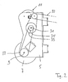
- Figure 1 is a schematic top view of a sweeping unit 1 shown, for example, on the front of a Floor cleaning machine is attachable. The floor cleaning machine itself is not reproduced. Just hinted at is a horizontal cross-section and aligned transversely to the direction of travel of the sweeping unit Broom 3, in its relative position to the front sweeping unit 1.
- the sweeping unit shown in a schematic top view 1 comprises a chassis or housing 5, on which in A plate brush 7 can be rotated on the left in the direction of travel is mounted, which is about a vertically aligned axis 9 turns. If necessary, the axis 9 in the direction of travel inclined slightly forward towards the vertical be so that the plate brush only with its leading Brush section rests on the floor and there In the direction of the arrow 10 dirt is transported inwards without dirt on the back side over the bristles can be transported to the outside.
- a sweeping belt deflection pulley arrangement is on the right in the direction of travel 11 provided that in Figure 1 in their maximum stop-limited extension position and in figure 2 in their stop-retracted position is reproduced. From the illustration it can be seen that the sweeping belt pulley arrangement 11 essentially with transverse to the working direction, i.e. in the lateral direction is retractable. As from the top view in the figures 1 to 3 can also be seen, the sweep is not exact at a 90 ° angle to the working direction or the longitudinal direction of the vehicle of the sweeping unit, but to its outer limit aligned slightly forward. Through this Working position becomes soil contamination and dirt still targeted to the inside of the cleaning unit and from there, for example, to a trailing roller brush forwarded.
- the sweeping belt deflection roller arrangement 11 has one Kehrbanditati 13 on, according to the greater detail according to Figure 3 with in the longitudinal direction lateral folds or folds or is formed with corresponding flanges 15, which are not serve only for reinforcement and stiffening, but through it on the Kehrbandango 13 directly or by attachment indirectly formed from additional components drain surfaces 16 ' on which the storage or Rollers 17 can run.
- FIG. 3 there is one on the inside of the device Pair of bearing rollers 17 and yet another in contrast further out but still arranged in the area of the housing 5 leading bearing roller 17 'shown.
- the two trunnions 19 of the bearing rollers 17 mounted on the housing edge are shown in Figures 1 and 2 can be seen.
- This endless strand 23 can be made of a circulating strip material or consist of a link chain or the like, on or on the bristles by means of suitable means are attached.
- Carrier 25 has a device-fixed seated drive wheel 27 cooperate, which follows also as a drive roller or as a toothed or sprocket 27 is referred to.
- the drive wheel 27 can be more suitable Be trained, namely not only as Gear or sprocket, but also, for example Friction wheel.
- Shock protection device 26 provided in the manner of a deflection bar, which is the actual sweeping belt pulley arrangement 11 protrudes both in the longitudinal and in the transverse direction and which when starting in the wall area or in the area of obstacles would hit first and thereby the sweeping belt pulley arrangement 11 in its entirety protects against damage.
- the impact protection device towers over the top view 26 but not the outer contour of the Bristles of the sweeping belt, so that without problems up to one Wall area and can be cleared in corners.
- 1 and 2 are several pulleys visible, namely a pulley 29, two on a common axis 31 rotating pulleys 33 and 35 and a further pulley 37, which is on the axis 9 to drive the plate brush 7 sits.
- Central drive shown central motor
- Central drive shown can be via a or several successive revolving belts 32 the Pulley 29 are driven, which on the axis 27 ' flanged on the outside of the housing, what about that this axis 27 'sitting gear or sprocket 27 (which is arranged below the housing wall 5) driven becomes.
- a change in the working width from maximum side extension to the retracted position of the sweeping belt deflection roller arrangement 11 can according to the embodiment be accomplished by continuing to provided adjustment wheel 39, which is also called Friction wheel 39 is referred to, in engagement with a drain surface 16 '' on the conveyor belt 13 is brought.
- the adjustment wheel 39 mentioned sits on a rocker 41, about the axis 27 'of the toothed and chain wheel 27 turns.
- the basic position is such that the Adjustment wheel 39 out of engagement (namely under training of an at least small air gap) with a corresponding one Drain surface 16 of the sweeping belt carrier 13 is located.
- the adjustment or friction wheel 39 is driven permanently via another belt 43 which is around the pulley 29 (a double pulley) and the big one Pulley 33 rotates.
- the pulley 33 sits above of the housing 5, the pulley axis 39 the Housing 5 penetrates and below the housing with the Friction wheel 39 is in drive connection.
- the axis 31 of the friction wheel 39 must be a corresponding large opening in the housing 5 provided be. According to the above description is therefore the rotational speed of the adjustment or Friction wheels 39 less than that of the toothed or sprocket 27.
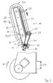
- the sweeping unit 1 designed like a front unit is with the side sweeping belt 23 and the side brush 7th via its suspension and anchoring device 47 tiltable at the top. As a result, the sweeping unit 1 can be disengaged to be brought. Because this also means the central drive belt 32 is relieved, so is the drive this sweeping unit, which can be attached at the front, is switched off, which relieves the load on the overall drive leads.
- the sweeping unit explained can be shown as Front unit on a floor cleaning or scrubber drier can preferably be used as an extension.
- the mentioned sweeping unit can also for example be trained in a large driver's seat machine and there for example, not only on the front, but also under be attached to the chassis.
Landscapes
- Brushes (AREA)
- Drying Of Solid Materials (AREA)
Abstract
Description
Die Erfindung betrifft ein Kehraggregat, insbesondere als
Zusatzeinrichtung für eine Bodenreinigungsmaschine oder
eine Scheuersaugmaschine nach dem Oberbegriff des Anspruches
1.The invention relates to a sweeping unit, in particular as
Additional device for a floor cleaning machine or
a scrubber drier according to the preamble of the
Ein gattungsbildendes Kehraggregat mit einem Kehrband in Form eines borstenbesetzten Endlosstranges, der um jeweils zwei Umlenkrollen umläuft, ist aus der EP 0 424 229 A1 bekannt geworden. Die Kehrband-Umlenkrollen-Anordnung mit dem um zwei Umlenkrollen umlaufenden Kehrband kann insgesamt quer zur Arbeitsrichtung aus- und einwärts verfahren werden, um die Arbeitsbreite an die räumlichen Verhältnisse anzupassen. Dabei ist die Kehrband-Umlenkrollen-Anordnung in Arbeitsrichtung mit geringer Vorwärtskomponente leicht schräg ausgerichtet. Da die gesamte Kehrband-Umlenkrollen-Anordnung einschließlich des zugehörigen Antriebs beim Anpassen der Arbeitsbreite ein- bzw. ausgefahren werden muß, erfordert dies einen nicht unbeachtlichen Bauaufwand.A generic sweeper with a sweeping belt in Form of a bristle-covered endless strand, which by each revolves around two deflecting rollers is known from EP 0 424 229 A1 known. The reverse conveyor pulley arrangement with the sweeping belt revolving around two deflection rollers can in total Move outwards and inwards across the working direction the working width to the spatial conditions adapt. Here is the reverse conveyor pulley arrangement in the working direction with little forward component slightly slanted. Because the entire sweeping belt pulley arrangement including the associated drive when adjusting the working width retracted or extended must be, this requires a not insignificant Construction effort.
Auch aus der WO 92/21275 ist ein Kehraggregat bekannt geworden, bei welchem zwei als Kehrbänder ausgebildete Endlosstränge vorgesehen sind, die jeweils um vier Umlenkrollen umlaufen. Drei dieser Umlenkrollen liegen innerhalb, die vierte außerhalb des Kehrbandes. Die drei in Arbeitsrichtung vorderen Umlenkrollen sind maschinenfest angeordnet, wohingegen die in Arbeitsrichtung hinterste Umlenkrolle aus- und einwärts verschwenkbar ist. Demgemäß trägt der jeweils in Arbeitsrichtung hintere Abschnitt des Kehrbandes zur Veränderbarkeit der Arbeitsbreite des Kehraggregates insgesamt bei, in dem die hinterste Umlenkrolle seitlich aus- bzw. eingeschwenkt werden kann. Der jeweils in Arbeitsrichtung vordere Abschnitt jedes Kehrbandes ist hingegen an der Veränderbarkeit der Arbeitsbreite nicht beteiligt. Die Kehrbänder sind in der Weise angetrieben, daß das jeweils in Arbeitsrichtung vordere Trum nach vorne einwärts kehrt, wodurch eine zentrale Aufnahme des Kehrgutes mittels einer Saugeinrichtung oder einer Walzenbürste möglich sein soll.A sweeping unit is also known from WO 92/21275 in which two trained as a sweeping belt Endless strands are provided, each around four pulleys circulate. Three of these pulleys are inside, the fourth outside the sweep band. The three in Direction of work front pulleys are machine-safe arranged, whereas the rearmost in the working direction Deflection roller can be pivoted in and out. Accordingly the rear section of the Sweeping belt for changing the working width of the sweeping unit overall, in which the rearmost pulley can be swung out or in laterally. The each is the front section of each sweeping belt in the working direction however, the variability of the working width is not involved. The sweeping belts are driven in the way that the front strand in the working direction is forward turns inwards, creating a central intake of the sweepings by means of a suction device or a roller brush should be possible.
Je schmaler jedoch die Arbeitsbreite ist, desto spitzer ist der Winkel zwischen dem jeweils hinteren Bereich des Kehrbandes und der Arbeitsrichtung. Bei minimaler Arbeitsbreite des Kehraggregates verlaufen die jeweils hinteren Bereiche der beiden Kehrbänder sogar parallel zur Arbeitsrichtung, was höchst unerwünscht ist. However, the narrower the working width, the more pointed is the angle between the rear area of the Sweeping belt and the direction of work. With a minimal working width of the sweeping unit run the rear Areas of the two sweeping belts even parallel to the working direction, which is highly undesirable.
Demgegenüber ist es Aufgabe der vorliegenden Erfindung, ausgehend von dem eingangs genannten gattungsbildenden Stand der Technik ein verbessertes Kehraggregat zu schaffen, welches eine bei allen Arbeitsbreiten optimale Reinigungsleistung aufweist, und dies bei vergleichsweise geringem Bauaufwand.In contrast, it is an object of the present invention starting from the generic type mentioned at the beginning State of the art to create an improved sweeping unit which is an optimal cleaning performance for all working widths has, and this at a comparatively low Construction effort.
Die Aufgabe wird erfindungsgemäß entsprechend den im Anspruch
1 angegebenen Merkmalen gelöst. Vorteilhafte Ausgestaltungen
der Erfindung sind in den Unteransprüchen angegeben.The task is according to the invention in accordance with the
Das erfindungsgemäße Kehraggregat zeichnet sich vor allem dadurch aus, daß die seitliche Verstellbarkeit und der Antrieb des Kehrbandes mit geringem baulichen Aufwand möglich wird. Denn in Abweichung zum Stand der Technik ist es nicht mehr erforderlich, daß die ein- und ausfahrbare Kehrband-Umlenkrollen-Anordnung mit einem separaten mitverfahrbaren Motor versehen sein muß, der natürlich neben dem erhöhten Bauaufwand auch einen entsprechenden Platz beansprucht. Denn ein mit verfahrbarer Motor erfordert ferner einen Tunnel im zentralen Gehäuseabschnitt des Kehraggregates, in welchem der Motor bei eingefahrenem Kehrband zu liegen kommt. Ebenso müßten ansonsten Kabel für den Motor herausgeführt werden, was ebenfalls Platz beansprucht.The sweeping unit according to the invention is particularly notable characterized in that the lateral adjustability and the Drive of the sweeping belt with little construction effort becomes possible. Because is in deviation from the state of the art it is no longer necessary that the retractable and retractable Sweeping belt deflection pulley arrangement with a separate movable one Engine must be provided, which of course next to a corresponding space due to the increased construction effort claimed. Because one with a movable motor requires also a tunnel in the central housing section of the Sweeping unit in which the engine when retracted Kehrband comes to rest. Otherwise cables would also have to be for the engine to be led out, which is also space claimed.
Demgegenüber schlägt die Erfindung vor, daß die Kehrband-Umlenkrollen-Anordnung zumindest zwei Umlenkrollen für den borstenbesetzten Endlosstrang aufweist, wobei beide Umlenkrollen nicht angetrieben werden. Es ist dazu ein versetztliegendes, separates und nicht mitverfahrbares Antriebsrad vorgesehen, das vorzugsweise am Kehraggregat ortsfest angeordnet ist, und zwar derart, daß eine Antriebsverbindung von diesem zusätzlichen Antriebsrad zu dem borstenbesetzten Endlosstrang sowohl in maximal ausgefahrener als aber auch in dazu relativ eingefahrener Position aufrecht erhalten wird.In contrast, the invention proposes that the sweeping belt deflection roller arrangement at least two pulleys for the Bristle-studded endless strand, both pulleys not be driven. It is an offset, separate drive wheel that cannot be moved provided, preferably on the sweeping unit is stationary, in such a way that a drive connection from this additional drive wheel too the bristle-filled endless strand both in the maximum extended but also in a relatively retracted one Position is maintained.
Die erfindungsgemäße Lösung bietet zudem den Vorteil, das zusätzliche gerätefest angebrachte Antriebsrad von einem Zentralmotor aus anzutreiben, beispielsweise mittels eines umlaufenden Riemens. Auch hierdurch lassen sich die Kosten gegenüber herkömmlichen Lösungen deutlich verringern.The solution according to the invention also offers the advantage that additional device-fixed drive wheel from one To drive the central motor, for example by means of a revolving belt. This also reduces costs significantly reduce compared to conventional solutions.
In einer bevorzugten Ausführungsform der Erfindung ist das Antriebsrad zum Antrieb des borstenbesetzten Endlosstranges auf der nach außen laufenden Kehrbandseite angeordnet. Dies bietet den weiteren Vorteil, daß sich das eingeleitete Drehmoment und die in entgegengesetzter Richtung verlaufende Reibkraft so ergänzen, daß das Kehrband immer auf die maximale Arbeitsbreite automatisch ausgefahren und gehalten wird. Zum Variieren der Arbeitsbreite ist dann lediglich eine zusätzliche Einrichtung erforderlich, um das Einfahren der Kehrband-Umlenkrollen-Anordnung zu ermöglichen.In a preferred embodiment of the invention that is Drive wheel for driving the bristle-covered endless strand arranged on the outward sweeping belt side. This offers the further advantage that the initiated Torque and the opposite direction Complete the frictional force so that the sweeping belt is always open the maximum working width is automatically extended and is held. Then to vary the working width only an additional facility is required to to enable the retraction belt deflection roller arrangement to be retracted.
In einer bevorzugten Weiterbildung der Erfindung besteht das zusätzlich vorgesehene Antriebsrad zum Antrieb des Kehrbandes aus einem Zahn- oder Kettenrad. In a preferred development of the invention the additionally provided drive wheel for driving the Sweeping belt from a gear or chain wheel.
An dem umlaufenden Kehrband sind dann ferner entsprechende Mitnehmer vorgesehen oder das Kehrband besteht aus einem Kehrbandträger in Form einer Gliederkette, welche dann mit dem erwähnten Zahn- oder Kettenrad zusammenwirkt.Corresponding are then also on the revolving conveyor belt Carrier provided or the sweep belt consists of a Kehrbandträger in the form of a link chain, which then with the mentioned gear or sprocket cooperates.
In einer bevorzugten Ausführungsform der Erfindung kann dabei eine Triebstockverzahnung zur Anwendung gelangen.In a preferred embodiment of the invention a rack tooth system is used.
Eine einfache Möglichkeit zum Einwärtsfahren der Kehrband-Umlenkrollen-Anordnung kann gemäß einer Weiterbildung der Erfindung durch ein zusätzliches Reibrad realisiert werden, das mit einem Kehrband-Umlenkrollen-Träger in Eingriff bringbar ist. Durch die Drehmomentübertragung läßt sich dabei allein durch Reibschluß die Kehrband-Umlenkrollen-Anordnung einwärts verfahren.An easy way to move the sweeping belt pulley arrangement inwards According to a further training of the Invention can be realized by an additional friction wheel, that engages with a sweeping belt pulley carrier is feasible. Due to the torque transmission the Kehrband-Umlenkrollen arrangement only by friction move inward.
Rein grundsätzlich wird angemerkt, daß das erwähnte und vorzugsweise in Form eines Zahn- oder Kettenrades ausgebildete Antriebsrad sowie das erwähnte Verstellrad auch so montiert werden können, daß über möglichst einen einzigen Zentralantrieb die Kehrband-Umlaufrollen-Anordnung stets in eingefahrener Position bewegt und gehalten und lediglich bei Betätigung einer separaten Einrichtung beispielsweise in Form des erwähnten Reibrades in die ausgefahrene Position zur Erzielung einer großen Arbeitsbreite verstellbar ist.Basically, it is noted that the mentioned and preferably designed in the form of a toothed or sprocket Drive wheel as well as the mentioned adjustment wheel can be mounted that over a single if possible Central drive always the sweeping belt circulation roller arrangement moved and held in the retracted position and only when operating a separate device, for example in the form of the mentioned friction wheel in the extended Adjustable position to achieve a large working width is.
Die Erfindung wird nachfolgend anhand von der Zeichnung und Ausführungsbeispielen erläutert. Dabei zeigen im einzelnen:
- Figur 1 :
- eine Draufsicht auf das erfindungsgemäße Kehraggregat, wie es beispielsweise an einer Bodenkehrmaschine frontseitig anbaubar ist (von der Kehrmaschine ist ansonsten lediglich in schematischer Horizontalschnittdarstellung eine zum Kehraggregat nachlaufend angeordnete Kehrwalze gezeigt);
- Figur 2 :
- eine entsprechende Draufsicht auf das erfindungsgemäße Kehraggregat bei eingefahrener Kehrband-Umlenkrollen-Anordnung;
- Figur 3 :
- eine Draufsicht auf die Kehrband-Umlenkrollen-Anordnung bei teilweise weggelassener Abdeckung des Kehraggregates;
- Figur 4 :
- eine Seitenansicht auf das erfindungsgemäße Kehraggregat in stirnseitiger Ansicht des Kehraggregates; und
- Figur 5 :
- eine entsprechende frontseitige Ansicht des Kehraggregates.
- Figure 1:
- a plan view of the sweeping unit according to the invention, as it can be attached to the front of a floor sweeper, for example (the sweeper is otherwise only shown in a schematic horizontal sectional view of a sweeping roller arranged after the sweeping unit);
- Figure 2:
- a corresponding plan view of the sweeping unit according to the invention with the sweeping belt deflection roller arrangement retracted;
- Figure 3:
- a plan view of the sweeping belt deflection roller arrangement with the cover of the sweeping unit partially omitted;
- Figure 4:
- a side view of the sweeping unit according to the invention in an end view of the sweeping unit; and
- Figure 5:
- a corresponding front view of the sweeping unit.
In Figur 1 ist in schematischer Draufsicht ein Kehraggregat
1 gezeigt, wie es beispielsweise frontseitig an einer
Bodenreinigungsmaschine anbaubar ist. Die Bodenreinigungsmaschine
selbst ist nicht wiedergegeben. Lediglich angedeutet
ist eine im Horizontalquerschnitt wiedergegebene
und quer zur Fahrtrichtung des Kehraggregates ausgerichtete
Kehrwalze 3, und zwar in ihrer Relativlage zu dem
frontseitig anbaubaren Kehraggregat 1.In Figure 1 is a schematic top view of a
Das in schematischer Draufsicht wiedergegebene Kehraggregat
1 umfaßt ein Chassis oder Gehäuse 5, an welchem in
Fahrtrichtung links liegend eine Tellerbürste 7 drehbar
gelagert ist, die um eine vertikal ausgerichtete Achse 9
dreht. Gegegebenenfalls kann die Achse 9 in Fahrtrichtung
gegenüber der Vertikalen leicht nach vorne laufend geneigt
sein, damit die Tellerbürste nur jeweils mit ihrem vorlaufenden
Bürstenabschnitt auf dem Boden aufliegt und dort
in Pfeilrichtung 10 Schmutz nach innen befördert, ohne daß
auf der rückwärtigen Seite über die Borsten wieder Schmutz
nach außen transportiert werden kann.The sweeping unit shown in a
In Fahrtrichtung rechts liegend ist eine Kehrband-Umlenkrollen-Anordnung
11 vorgesehen, die in Figur 1 in ihrer
maximalen anschlagsbegrenzten Ausfahrposition und in Figur
2 in ihrer anschlagsbegrenzten eingefahrenen Position
wiedergegeben ist. Aus der Darstellung ist ersichtlich,
daß die Kehrband-Umlenkrollen-Anordnung 11 im wesentlichen
mit quer zur Arbeitsrichtung, also in Seitenrichtung, aus- und
einfahrbar ist. Wie aus der Draufsicht in den Figuren
1 bis 3 auch ersichtlich ist, ist das Kehrband nicht exakt
im 90°-Winkel zur Arbeitsrichtung oder Fahrzeuglängsrichtung
des Kehraggregates, sondern zu seiner äußeren Begrenzung
hin leicht vorlaufend ausgerichtet. Durch diese
Arbeitsstellung werden Bodenverunreinigungen und Schmutz
noch gezielt zur innenseitigen Mitte des Putzaggregates
und von dort beispielsweise zu einer nachlaufenden Kehrwalze
weiterbefördert.A sweeping belt deflection pulley arrangement is on the right in the direction of
Die Kehrband-Umlenkrollen-Anordnung 11 weist dabei einen
Kehrbandträger 13 auf, der entsprechend der größeren Detailwiedergabe
gemäß Figur 3 mit in Längserstreckungsrichtung
seitlich liegenden Kantungen oder Faltungen oder
mit entsprechenden Flanschen 15 ausgebildet ist, die nicht
nur der Verstärkung und Versteifung dienen, sondern wodurch
am Kehrbandträger 13 unmittelbar oder durch Anbau
von Zusatzkomponenten mittelbar Ablaufflächen 16' gebildet
werden, an welchen die nachfolgend noch erwähnten Lager- oder
Laufrollen 17 ablaufen können.The sweeping belt
In Figur 3 ist jeweils ein geräteinnenseitig liegendes
Paar von Lagerollen 17 und noch eine weitere demgegenüber
weiter außen aber noch im Bereich des Gehäuses 5 angeordnete
vorlaufende Lagerrolle 17' gezeigt. Die jeweils mit
der Lagerrolle 17' zusammenwirkende und auf der gegenüberliegenden
Seite des Kehrbandträgers vorgesehene weitere
Lagerrolle ist der besseren Darstellbarkeit wegen in
Figur 3 nicht eingezeichnet worden. Die beiden Lagerzapfen
19 der gehäuserandseitig montierten Lagerrollen 17 sind in
den Figur 1 und 2 ersichtlich.In FIG. 3 there is one on the inside of the device
Pair of bearing
An dem Kehrbandträger 13 sind außen- und innenseitig jeweils
eine Umlenkrolle 21 gehalten und gelagert, um die
herum ein borstenbesetzter Endlosstrang 23 umläuft.On the
Dieser Endlosstrang 23 kann aus einem umlaufenden Bandmaterial
oder aus einer Gliederkette oder dergleichen bestehen,
an dem bzw. an der Borsten mittels geeigneter Mittel
befestigt sind.This
Im gezeigten Ausführungsbeispiel gemäß Figur 3 ist ersichtlich,
daß der Endlosstrang 23 im wesentlichen vertikal
ausgerichtete und in Umlaufrichtung nebeneinandersitzende
Mitnehmer 25 aufweist, die mit einem gerätefest
sitzenden Antriebsrad 27 zusammenwirken, welches nachfolgend
auch als Antriebsrolle oder als Zahn- oder Kettenrad
27 bezeichnet wird. Das Antriebsrad 27 kann dabei in geeigneter
Weise ausgebildet sein, nämlich nicht nur als
Zahn- oder Kettenrad, sondern beispielsweise auch als
Reibrad.In the exemplary embodiment shown in FIG. 3, it can be seen
that the
Schließlich ist an dem Kehrbandträger 13 auch noch eine
Stoßschutzeinrichtung 26 nach Art eines Abweisbügels vorgesehen,
die die eigentliche Kehrband-Umlenkrollen-Anordnung
11 sowohl in Längs- als auch in Querrichtung überragt
und welche beim Anfahren im Wandbereich oder im Bereich
von Hindernissen zuerst anschlagen würde und dadurch
die Kehrband-Umlenkrollen-Anordnung 11 in ihrer Gesamtheit
vor Beschädigung schützt. In Draufsicht überragt die Stoßschutzeinrichtung
26 allerdings nicht die Außenkontur der
Borsten des Kehrbandes, so daß problemlos bis an einen
Wandbereich und in Ecken geräumt werden kann.Finally, there is also one on the
In der Draufsicht gemäß Figur 1 und 2 sind mehrere Riemenscheiben
sichtbar, nämlich eine Riemenscheibe 29, zwei auf
einer gemeinsamen Achse 31 drehende Riemenscheiben 33 und
35 und eine weitere Riemenscheibe 37, die auf der Achse 9
zum Antrieb der Tellerbürste 7 sitzt.1 and 2 are several pulleys
visible, namely a
Von einem auf der Kehrmaschine sitzenden und nicht näher
gezeigten Zentralantrieb (Zentralmotor) kann über einen
oder mehrere aufeinanderfolgende, umlaufende Riemen 32 die
Riemenscheibe 29 angetrieben werden, die auf der Achse 27'
gehäuseaußenseitig aufgeflanscht ist, worüber das auf
dieser Achse 27' sitzende Zahn- bzw. Kettenrad 27 (welches
unterhalb der Gehäusewandung 5 angeordnet ist) angetrieben
wird.From someone sitting on the sweeper and not closer
Central drive shown (central motor) can be via a
or several successive revolving
Über den Antrieb des nur teilweise dargestellten und um
die Riemenscheibe 29 umlaufenden Riemens 32 wird dadurch
das Zahn- und Kettenrad 27 gemäß der Draufsicht in Figur
3 im Uhrzeigersinn angetrieben, wodurch der mit Mitnehmern
25 versehene Endlosstrang 23 entgegengesetzt dem Uhrzeigersinn
mit den darauf befestigten Borsten um die beiden
Umlenkrollen 21 umläuft. Dabei wird die Kehrband-Umlenkrollen-Anordnung
11 selbsttätig in ihrer maximal auswärts
gerichteten Seitenkehrlage verschwenkt, wie sich aus den
folgenden Überlegungen ergibt.About the drive of the only partially shown and around
the
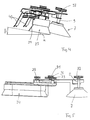
Gemäß den Darstellungen nach Figuren 4 und 5 ist ersichtlich,
daß das Kehrband 23 mit seinen Borsten 24 unter
einem spitzen Winkel α zum Boden in Fahrtrichtung nach
vorn geneigt ausgerichtet ist, um zu gewährleisten, daß
der entsprechend der Drehrichtung der Borsten einwärts
geführte Schmutz auf der in Fahrtrichtung hinteren Kehrbandseite
nicht wieder nach außen zurückgeführt wird,
sondern über die eingangs erwähnte Hauptkehrwalze 3 aufgenommen
und in ein Schmutzfach abgelagert werden kann.
Ferner werden durch diese Anordnung die Reibungsverluste
bzw. Energieeinsatz minimiert. Da zudem lediglich aber die
Borsten 24 an der vorlaufenden Kehrbandseite, wo sie von
außen nach innen gemäß Pfeildarstellung 38 bewegt werden,
den Boden berühren, wird gewährleistet, daß bei Anordnung
des Zahn- oder Kettenrades 27 auf der nach außen laufenden
Kehrbandseite über das eingeleitete Drehmoment die in
entgegengesetzter Richtung verlaufende Reibkraft das Kehrband
immer auf die maximale Arbeitsbreite automatisch
eingestellt wird.4 and 5 it can be seen that
that the
Im gezeigten Ausführungsbeispiel ist für das Zahn- und
Kettenrad 27 und die damit in Eingriff gelangenden Mitnehmer
25 am Endlosstrang 23 eine Triebstockverzahnung gewählt
worden. Aber es sind auch andere Zahnverbindungen
möglich, selbst eine Reib-Antriebsverbindung unter Verwendung
eines Reibrades.In the embodiment shown is for the tooth and
Eine Veränderung der Arbeitsbreite von maximaler Seitenerstreckung
zur eingefahrenen Position der Kehrband-Umlenkrollen-Anordnung
11 kann gemäß dem Ausführungsbeispiel
dadurch bewerkstelligt werden, daß ein weiterhin
vorgesehenes Verstellrad 39, welches nachfolgend auch als
Reibrad 39 bezeichnet wird, in Eingriff mit einer Ablauffläche
16'' am Kehrbandträger 13 gebracht wird.A change in the working width from maximum side extension
to the retracted position of the sweeping belt
Das erwähnte Verstellrad 39 sitzt dabei auf einer Schwinge
41, die um die Achse 27' des Zahn- und Kettenrades 27
dreht. Die Grundstellung ist dabei derart, daß sich das
Verstellrad 39 außer Eingriff (nämlich unter Ausbildung
eines zumindest geringen Luftspaltes) mit einer entsprechenden
Ablauffläche 16 des Kehrbandträgers 13 befindet.The
Durch Betätigung eines nicht näher gezeigten Bowden- oder
Seilzuges von einer Handhabungs- oder Bedieneinheit der
Kehrmaschine aus kann beispielsweise die Schwinge 41 nunmehr
so geringfügig unter Überwindung des erwähnten Luftspaltes
verstellt werden, daß das Verstell- oder Reibrad
39 mit seiner Umfangsfläche an die entsprechende Ablauffläche
16'' des Kehrbandträgers 13 angedrückt wird und in
Reibkontakt tritt, so daß dadurch die Rotationsbewegung
des Reibrades 39 entgegengesetzt dem Uhrzeigersinn der
Kehrbandträger 13 in seine eingefahrene Position verfahren
wird.By operating a Bowden or not shown
Cable from a handling or operating unit
Sweeper can now, for example, the
Der Antrieb des Verstell- bzw. Reibrades 39 erfolgt dabei
permanent über einen weiteren Riemen 43, der um die Riemenscheibe
29 (eine Doppelriemenscheibe) und die große
Riemenscheibe 33 umläuft. Die Riemenscheibe 33 sitzt oberhalb
des Gehäuses 5, wobei die Riemenscheiben-Achse 39 das
Gehäuse 5 durchsetzt und unterhalb des Gehäuses mit dem
Reibrad 39 in Triebverbindung steht. Zur Ermöglichung der
erwähnten geringfügigen Verstellbarkeit der Schwinge 41
und damit der Achse 31 des Reibrades 39 muß ein entsprechend
groß bemessener Durchbruch im Gehäuse 5 vorgesehen
sein. Entsprechend der vorstehend genannten Schilderung
ist von daher die Drehgeschwindigkeit des Verstell- oder
Reibrades 39 geringer als die des Zahn- oder Kettenrades
27. Im übrigen kann durch einen weiteren, um die kleinere
Riemenscheibe 35 und um die dem Seitenbesen 7 zugeordnete
Riemenscheibe 37 umlaufenden Riemen 45 eine Reduzierung
der Drehzahl des Seitenbesens nach Art einer Untersetzungsstufe
auf ein Viertel der Drehzahl des Zahn- oder
Kettenrades 27 ermöglicht werden.The adjustment or
Sobald durch erneute gegensinnige Betätigung des Bowdenoder
Seilzuges oder eines ebenfalls nicht näher dargestellten
Hebelübertragungsgestänges (oder beispielsweise nur
durch Nachlassen der Betätigungseinrichtung, die aufgrund
einer verwendeten Feder dadurch wieder in ihre Ausgangsstellung
zurückbewegt wird) das Verstellrad 39 wieder
außer Eingriff mit einer Ablauffläche 16' des Kehrbandträgers
13 gebracht ist, bewegt sich die Kehrband-Umlenkrollen-Anordnung
11 über das vom Zahn- und Kettenrad
27 eingeleitete Drehmoment wieder selbsttätig in die maximal
ausgefahrene Position. Nur der Vollständigkeit halber
wird erwähnt, daß grundsätzlich das Zahn- bzw. Kettenrad
27 auch auf der nach innen laufenden Kehrbandseite angeordnet
sein kann, wobei dann zum Ausfahren der Kehrband-Umlenkrollen-Anordnung
11 beispielsweise ein entsprechendes
Verstell- oder Reibrad 39 benötigt werden würde, um
unter entsprechendem Eingriff mit einer geeigneten Ablauffläche
am Kehrbandträger 13 diesen bei feststehendem Antriebsrad
27 in maximale Kehrbreitenlage auszufahren.As soon as you press the Bowdenoder again in opposite directions
Cable or one not shown
Lever transmission linkage (or just for example
by weakening the actuator due to
a spring used back to its original position
is moved back) the
Das nach Art einer Fronteinheit gestaltete Kehraggregat 1
ist mit dem seitlichen Kehrband 23 und dem Seitenbesen 7
über seine Aufhäng- und Verankerungseinrichtung 47 nach
oben kippbar. Dadurch kann das Kehraggregat 1 außer Eingriff
gebracht werden. Da dadurch auch der zentrale Antriebsriemen
32 entlastet wird, wird damit auch der Antrieb
dieses frontseitig anbaubaren Kehraggregates abgeschaltet,
was zu einer Entlastung des Gesamtantriebes
führt.The
Das erläuterte Kehraggregat kann wie dargestellt als Fronteinheit an einer Bodenreinigungs- oder einer Scheuersaugmaschine vorzugsweise anbaubar verwendet werden. Das erwähnte Kehraggregat kann aber ebenso beispielsweise bei einer großen Fahrersitzmaschine ausgebildet sein und dort beispielsweise nicht nur frontseitig, sondern auch unter dem Chassis angebracht sein.The sweeping unit explained can be shown as Front unit on a floor cleaning or scrubber drier can preferably be used as an extension. The mentioned sweeping unit can also for example be trained in a large driver's seat machine and there for example, not only on the front, but also under be attached to the chassis.
Claims (19)
gekennzeichnet durch die folgenden weiteren Merkmale,
characterized by the following further features,
Applications Claiming Priority (2)
| Application Number | Priority Date | Filing Date | Title |
|---|---|---|---|
| DE1996138425 DE19638425C2 (en) | 1996-09-19 | 1996-09-19 | Sweeping belt deflection roller arrangement |
| DE19638425 | 1996-09-19 |
Publications (2)
| Publication Number | Publication Date |
|---|---|
| EP0830833A2 true EP0830833A2 (en) | 1998-03-25 |
| EP0830833A3 EP0830833A3 (en) | 1999-10-06 |
Family
ID=7806238
Family Applications (1)
| Application Number | Title | Priority Date | Filing Date |
|---|---|---|---|
| EP97116273A Withdrawn EP0830833A3 (en) | 1996-09-19 | 1997-09-18 | Sweeping unit |
Country Status (2)
| Country | Link |
|---|---|
| EP (1) | EP0830833A3 (en) |
| DE (1) | DE19638425C2 (en) |
Families Citing this family (3)
| Publication number | Priority date | Publication date | Assignee | Title |
|---|---|---|---|---|
| DE19723673C1 (en) * | 1997-06-05 | 1999-03-04 | Hefter Maschinenbau | Sweeping apparatus for floor cleaning |
| AU2423499A (en) * | 1999-01-20 | 1999-08-02 | Kurt Zachhuber | Floor treatment machine |
| DE102018103835B3 (en) | 2018-02-21 | 2019-08-22 | Hefter Cleantech Gmbh | Soil preparation machine, in particular floor cleaning machine |
Family Cites Families (4)
| Publication number | Priority date | Publication date | Assignee | Title |
|---|---|---|---|---|
| FR2652099A1 (en) * | 1989-09-18 | 1991-03-22 | Grzeszczak Wactaw | Vehicle for cleaning highways with a mechanical brush having increased working surface area and mechanical brush equipping the same |
| FR2653359A1 (en) * | 1989-10-19 | 1991-04-26 | Protee | APPARATUS FOR CLEANING A SURFACE, METHOD FOR CLEANING USING SAME, AND APPLICATION OF THIS METHOD FOR CLEANING THE FLOOR OF A PUBLIC TRANSPORT VEHICLE. |
| DE4118708C1 (en) * | 1991-06-07 | 1992-08-20 | Zachhuber Kurt | |
| DE4427726C2 (en) * | 1994-08-05 | 1996-11-07 | Hefter Maschinenbau | Sweeping unit |
-
1996
- 1996-09-19 DE DE1996138425 patent/DE19638425C2/en not_active Expired - Fee Related
-
1997
- 1997-09-18 EP EP97116273A patent/EP0830833A3/en not_active Withdrawn
Also Published As
| Publication number | Publication date |
|---|---|
| EP0830833A3 (en) | 1999-10-06 |
| DE19638425A1 (en) | 1997-03-13 |
| DE19638425C2 (en) | 1998-05-07 |
Similar Documents
| Publication | Publication Date | Title |
|---|---|---|
| DE19851470B4 (en) | Round baler for agricultural crop | |
| DE69316145T2 (en) | Mower with drive device for preparation rollers | |
| DE19607527C2 (en) | Sliding door operating device for a vehicle and motor vehicle with such a sliding door operating device | |
| DE60131524T2 (en) | Round baler | |
| EP0787425B1 (en) | Chopper and conveying device | |
| EP3468820B1 (en) | Construction machine, in particular a soil compacting machine, specifically a rubber-wheeled roller, method for operating a construction machine and method for producing a construction machine | |
| DE3628605C2 (en) | ||
| DE3734560A1 (en) | Conveying device | |
| DE2941293C2 (en) | ||
| EP0808753B2 (en) | Vertical washing brush | |
| DE68920865T2 (en) | Bucket conveyor for the continuous unloading of ships. | |
| EP1401680A1 (en) | Loading base for a vehicle and loading device | |
| DE19524748C2 (en) | Washing device for a car wash | |
| EP0830833A2 (en) | Sweeping unit | |
| DE69512559T2 (en) | Haymaking machine, especially a rake for forage | |
| DE19637685C2 (en) | Cleaning machine with swiveling side brush | |
| DE69304558T2 (en) | Haymaking machine with a frame provided with controlled support wheels | |
| EP1208736B1 (en) | Device for emptying a loading space | |
| DE102021118663A1 (en) | GROUND MILLING MACHINE | |
| EP0671374A2 (en) | Compost turning machine | |
| DE8623442U1 (en) | Device for sweeping surfaces | |
| EP1539512B1 (en) | Road-rail vehicle comprising a drive device for operating on rails | |
| DE69916533T2 (en) | Mower / conditioner | |
| DE4427726C2 (en) | Sweeping unit | |
| EP0688707B1 (en) | Device for transporting of vehicles through a car wash |
Legal Events
| Date | Code | Title | Description |
|---|---|---|---|
| PUAI | Public reference made under article 153(3) epc to a published international application that has entered the european phase |
Free format text: ORIGINAL CODE: 0009012 |
|
| AK | Designated contracting states |
Kind code of ref document: A2 Designated state(s): AT DE FR GB IT NL |
|
| PUAL | Search report despatched |
Free format text: ORIGINAL CODE: 0009013 |
|
| AK | Designated contracting states |
Kind code of ref document: A3 Designated state(s): AT BE CH DE DK ES FI FR GB GR IE IT LI LU MC NL PT SE |
|
| RIC1 | Information provided on ipc code assigned before grant |
Free format text: 6A 47L 11/40 A, 6A 47L 11/24 B, 6E 01H 1/05 B |
|
| 17P | Request for examination filed |
Effective date: 19991223 |
|
| AKX | Designation fees paid |
Free format text: AT DE FR GB IT NL |
|
| 17Q | First examination report despatched |
Effective date: 20010618 |
|
| STAA | Information on the status of an ep patent application or granted ep patent |
Free format text: STATUS: THE APPLICATION IS DEEMED TO BE WITHDRAWN |
|
| 18D | Application deemed to be withdrawn |
Effective date: 20011030 |