EP0830501B1 - Torch assembly - Google Patents
Torch assembly Download PDFInfo
- Publication number
- EP0830501B1 EP0830501B1 EP96917856A EP96917856A EP0830501B1 EP 0830501 B1 EP0830501 B1 EP 0830501B1 EP 96917856 A EP96917856 A EP 96917856A EP 96917856 A EP96917856 A EP 96917856A EP 0830501 B1 EP0830501 B1 EP 0830501B1
- Authority
- EP
- European Patent Office
- Prior art keywords
- fuel
- assembly
- air
- igniter
- ignition
- Prior art date
- Legal status (The legal status is an assumption and is not a legal conclusion. Google has not performed a legal analysis and makes no representation as to the accuracy of the status listed.)
- Expired - Lifetime
Links
Images
Classifications
-
- F—MECHANICAL ENGINEERING; LIGHTING; HEATING; WEAPONS; BLASTING
- F01—MACHINES OR ENGINES IN GENERAL; ENGINE PLANTS IN GENERAL; STEAM ENGINES
- F01N—GAS-FLOW SILENCERS OR EXHAUST APPARATUS FOR MACHINES OR ENGINES IN GENERAL; GAS-FLOW SILENCERS OR EXHAUST APPARATUS FOR INTERNAL-COMBUSTION ENGINES
- F01N3/00—Exhaust or silencing apparatus having means for purifying, rendering innocuous, or otherwise treating exhaust
- F01N3/08—Exhaust or silencing apparatus having means for purifying, rendering innocuous, or otherwise treating exhaust for rendering innocuous
- F01N3/10—Exhaust or silencing apparatus having means for purifying, rendering innocuous, or otherwise treating exhaust for rendering innocuous by thermal or catalytic conversion of noxious components of exhaust
- F01N3/18—Exhaust or silencing apparatus having means for purifying, rendering innocuous, or otherwise treating exhaust for rendering innocuous by thermal or catalytic conversion of noxious components of exhaust characterised by methods of operation; Control
-
- F—MECHANICAL ENGINEERING; LIGHTING; HEATING; WEAPONS; BLASTING
- F01—MACHINES OR ENGINES IN GENERAL; ENGINE PLANTS IN GENERAL; STEAM ENGINES
- F01N—GAS-FLOW SILENCERS OR EXHAUST APPARATUS FOR MACHINES OR ENGINES IN GENERAL; GAS-FLOW SILENCERS OR EXHAUST APPARATUS FOR INTERNAL-COMBUSTION ENGINES
- F01N3/00—Exhaust or silencing apparatus having means for purifying, rendering innocuous, or otherwise treating exhaust
- F01N3/08—Exhaust or silencing apparatus having means for purifying, rendering innocuous, or otherwise treating exhaust for rendering innocuous
- F01N3/10—Exhaust or silencing apparatus having means for purifying, rendering innocuous, or otherwise treating exhaust for rendering innocuous by thermal or catalytic conversion of noxious components of exhaust
- F01N3/24—Exhaust or silencing apparatus having means for purifying, rendering innocuous, or otherwise treating exhaust for rendering innocuous by thermal or catalytic conversion of noxious components of exhaust characterised by constructional aspects of converting apparatus
- F01N3/26—Construction of thermal reactors
-
- F—MECHANICAL ENGINEERING; LIGHTING; HEATING; WEAPONS; BLASTING
- F01—MACHINES OR ENGINES IN GENERAL; ENGINE PLANTS IN GENERAL; STEAM ENGINES
- F01N—GAS-FLOW SILENCERS OR EXHAUST APPARATUS FOR MACHINES OR ENGINES IN GENERAL; GAS-FLOW SILENCERS OR EXHAUST APPARATUS FOR INTERNAL-COMBUSTION ENGINES
- F01N3/00—Exhaust or silencing apparatus having means for purifying, rendering innocuous, or otherwise treating exhaust
- F01N3/08—Exhaust or silencing apparatus having means for purifying, rendering innocuous, or otherwise treating exhaust for rendering innocuous
- F01N3/10—Exhaust or silencing apparatus having means for purifying, rendering innocuous, or otherwise treating exhaust for rendering innocuous by thermal or catalytic conversion of noxious components of exhaust
- F01N3/24—Exhaust or silencing apparatus having means for purifying, rendering innocuous, or otherwise treating exhaust for rendering innocuous by thermal or catalytic conversion of noxious components of exhaust characterised by constructional aspects of converting apparatus
- F01N3/28—Construction of catalytic reactors
- F01N3/2882—Catalytic reactors combined or associated with other devices, e.g. exhaust silencers or other exhaust purification devices
-
- F—MECHANICAL ENGINEERING; LIGHTING; HEATING; WEAPONS; BLASTING
- F02—COMBUSTION ENGINES; HOT-GAS OR COMBUSTION-PRODUCT ENGINE PLANTS
- F02C—GAS-TURBINE PLANTS; AIR INTAKES FOR JET-PROPULSION PLANTS; CONTROLLING FUEL SUPPLY IN AIR-BREATHING JET-PROPULSION PLANTS
- F02C7/00—Features, components parts, details or accessories, not provided for in, or of interest apart form groups F02C1/00 - F02C6/00; Air intakes for jet-propulsion plants
- F02C7/26—Starting; Ignition
- F02C7/264—Ignition
-
- F—MECHANICAL ENGINEERING; LIGHTING; HEATING; WEAPONS; BLASTING
- F23—COMBUSTION APPARATUS; COMBUSTION PROCESSES
- F23C—METHODS OR APPARATUS FOR COMBUSTION USING FLUID FUEL OR SOLID FUEL SUSPENDED IN A CARRIER GAS OR AIR
- F23C13/00—Apparatus in which combustion takes place in the presence of catalytic material
-
- F—MECHANICAL ENGINEERING; LIGHTING; HEATING; WEAPONS; BLASTING
- F23—COMBUSTION APPARATUS; COMBUSTION PROCESSES
- F23C—METHODS OR APPARATUS FOR COMBUSTION USING FLUID FUEL OR SOLID FUEL SUSPENDED IN A CARRIER GAS OR AIR
- F23C9/00—Combustion apparatus characterised by arrangements for returning combustion products or flue gases to the combustion chamber
- F23C9/006—Combustion apparatus characterised by arrangements for returning combustion products or flue gases to the combustion chamber the recirculation taking place in the combustion chamber
-
- F—MECHANICAL ENGINEERING; LIGHTING; HEATING; WEAPONS; BLASTING
- F23—COMBUSTION APPARATUS; COMBUSTION PROCESSES
- F23Q—IGNITION; EXTINGUISHING-DEVICES
- F23Q11/00—Arrangement of catalytic igniters
- F23Q11/04—Arrangement of catalytic igniters at the burner
-
- F—MECHANICAL ENGINEERING; LIGHTING; HEATING; WEAPONS; BLASTING
- F23—COMBUSTION APPARATUS; COMBUSTION PROCESSES
- F23R—GENERATING COMBUSTION PRODUCTS OF HIGH PRESSURE OR HIGH VELOCITY, e.g. GAS-TURBINE COMBUSTION CHAMBERS
- F23R3/00—Continuous combustion chambers using liquid or gaseous fuel
- F23R3/28—Continuous combustion chambers using liquid or gaseous fuel characterised by the fuel supply
- F23R3/34—Feeding into different combustion zones
- F23R3/343—Pilot flames, i.e. fuel nozzles or injectors using only a very small proportion of the total fuel to insure continuous combustion
-
- F—MECHANICAL ENGINEERING; LIGHTING; HEATING; WEAPONS; BLASTING
- F23—COMBUSTION APPARATUS; COMBUSTION PROCESSES
- F23R—GENERATING COMBUSTION PRODUCTS OF HIGH PRESSURE OR HIGH VELOCITY, e.g. GAS-TURBINE COMBUSTION CHAMBERS
- F23R3/00—Continuous combustion chambers using liquid or gaseous fuel
- F23R3/40—Continuous combustion chambers using liquid or gaseous fuel characterised by the use of catalytic means
-
- F—MECHANICAL ENGINEERING; LIGHTING; HEATING; WEAPONS; BLASTING
- F01—MACHINES OR ENGINES IN GENERAL; ENGINE PLANTS IN GENERAL; STEAM ENGINES
- F01N—GAS-FLOW SILENCERS OR EXHAUST APPARATUS FOR MACHINES OR ENGINES IN GENERAL; GAS-FLOW SILENCERS OR EXHAUST APPARATUS FOR INTERNAL-COMBUSTION ENGINES
- F01N2250/00—Combinations of different methods of purification
- F01N2250/04—Combinations of different methods of purification afterburning and catalytic conversion
-
- F—MECHANICAL ENGINEERING; LIGHTING; HEATING; WEAPONS; BLASTING
- F01—MACHINES OR ENGINES IN GENERAL; ENGINE PLANTS IN GENERAL; STEAM ENGINES
- F01N—GAS-FLOW SILENCERS OR EXHAUST APPARATUS FOR MACHINES OR ENGINES IN GENERAL; GAS-FLOW SILENCERS OR EXHAUST APPARATUS FOR INTERNAL-COMBUSTION ENGINES
- F01N3/00—Exhaust or silencing apparatus having means for purifying, rendering innocuous, or otherwise treating exhaust
- F01N3/08—Exhaust or silencing apparatus having means for purifying, rendering innocuous, or otherwise treating exhaust for rendering innocuous
- F01N3/10—Exhaust or silencing apparatus having means for purifying, rendering innocuous, or otherwise treating exhaust for rendering innocuous by thermal or catalytic conversion of noxious components of exhaust
- F01N3/24—Exhaust or silencing apparatus having means for purifying, rendering innocuous, or otherwise treating exhaust for rendering innocuous by thermal or catalytic conversion of noxious components of exhaust characterised by constructional aspects of converting apparatus
- F01N3/30—Arrangements for supply of additional air
-
- F—MECHANICAL ENGINEERING; LIGHTING; HEATING; WEAPONS; BLASTING
- F02—COMBUSTION ENGINES; HOT-GAS OR COMBUSTION-PRODUCT ENGINE PLANTS
- F02B—INTERNAL-COMBUSTION PISTON ENGINES; COMBUSTION ENGINES IN GENERAL
- F02B1/00—Engines characterised by fuel-air mixture compression
- F02B1/02—Engines characterised by fuel-air mixture compression with positive ignition
- F02B1/04—Engines characterised by fuel-air mixture compression with positive ignition with fuel-air mixture admission into cylinder
-
- F—MECHANICAL ENGINEERING; LIGHTING; HEATING; WEAPONS; BLASTING
- F23—COMBUSTION APPARATUS; COMBUSTION PROCESSES
- F23C—METHODS OR APPARATUS FOR COMBUSTION USING FLUID FUEL OR SOLID FUEL SUSPENDED IN A CARRIER GAS OR AIR
- F23C2900/00—Special features of, or arrangements for combustion apparatus using fluid fuels or solid fuels suspended in air; Combustion processes therefor
- F23C2900/13002—Catalytic combustion followed by a homogeneous combustion phase or stabilizing a homogeneous combustion phase
-
- F—MECHANICAL ENGINEERING; LIGHTING; HEATING; WEAPONS; BLASTING
- F23—COMBUSTION APPARATUS; COMBUSTION PROCESSES
- F23D—BURNERS
- F23D2207/00—Ignition devices associated with burner
-
- F—MECHANICAL ENGINEERING; LIGHTING; HEATING; WEAPONS; BLASTING
- F23—COMBUSTION APPARATUS; COMBUSTION PROCESSES
- F23D—BURNERS
- F23D2900/00—Special features of, or arrangements for burners using fluid fuels or solid fuels suspended in a carrier gas
- F23D2900/00014—Pilot burners specially adapted for ignition of main burners in furnaces or gas turbines
Definitions
- the invention relates to an assembly for ignition of gas turbine combustors.
- this invention relates to devices for continuous stabilization/re-ignition of lean low NO x combustion.
- This invention also relates to igniters for use in place of conventional spark plug fuel ignition systems.
- combustor wall mounted igniters typically a spark plug
- combustor light-off This requires the presence of fuel close to the wall.
- combustor designs tend to be a compromise between ignition and operational requirements.
- ignition should be achieved right at the fuel source so that ignition of the initial fuel flow is possible. This avoids the necessity to dump unburned fuel into the combustor prior to ignition (creating the potential for hot starts or explosive detonations with consequent damage to the turbine) and enables the use of spray patterns which keep fuel away from the combustor walls.
- U.S. patent 4,938,019 describes a fuel nozzle with an integrated spark plug igniter assembly
- U.S. patent 4,825,658 describes a fuel nozzle with a catalytic glow plug igniter assembly.
- Such designs have major drawbacks which limit utility.
- a spark plug integrated into an injector is subject to fouling if wetted by liquid turbine fuel, rendering it inoperative.
- size limitations reduce spark plug life.
- Patent 4,825,658 eliminates the fouling problem of spark plugs, the glow plug is designed such that the return flow of the recirculating flow downstream of the injector contacts the hot glow plug surface resulting in ignition of the downstream recirculating gases.
- the initial direction of the incoming fuel-air flow from the swirler is away from the glow plug considerable fuel can travel downstream before sufficient fuel is injected to increase the recirculation zone fuel concentration high enough at the glow plug to allow ignition.
- fuel should be ignited immediately as it enters the combustor.
- GB Patent 869 652 discloses as ignition device for a combustion chamber of an engine, means for heating a combustion supporting gas such as air and a chamber for mixing vaporised fuel and the heated air. The mixture issues through a jet, an igniter being provided to ignite the jetted mixture.
- atomized fuel entering a gas turbine combustor is reliably ignited as it enters the combustor by contact with a continuous pilot flame projected into the combustor distal to the combustor walls, at a location to ignite the incoming fuel.
- the present invention offers the advantages of away-from-the-wall ignition coupled with continuous flame stabilization by providing for projection of the pilot flame into a combustor, whether from the liner wall or from the combustor centerline, such as if mounted within a fuel nozzle.
- a torch assembly for ignition of fuel in admixture with air within a gas combustor which comprises; a tubular chamber; a hot surface igniter contained in the tubular chamber; means for atomizing fuel into admixture with air; electrical means for heating the igniter, an exit opening out of the chamber for projection of a pilot flame into a combustor, conduit means for carrying the atomized fuel from the means for atomizing fuel into the tubular chamber; characterized in that the assembly further comprises a partial reaction zone in the tubular chamber; and means for addition of additional air into the partial reaction zone.
- a torch assembly for the ignition of air/fuel mixtures in the walled combustion chamber of a gas turbine, which comprises; a tube defining a tube lumen, said lumen having a first end and a second end and a first opening into a combustion chamber; means for atomizing fuel in a mixture with air, mounted in the tube lumen, proximal to the second end; conduit means for delivery of a liquid fuel to the atomizer; passage means for carrying air to the atomizer; catalytic hot surface ignition means for igniting atomized fuel/air mixtures, positioned in the lumen between the atomizer and the first opening, characterized in that the assembly further comprises; secondary air addition means positioned to carry secondary air into the tube lumen between the igniter and the first opening.
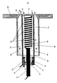
- the drawing shows, by way of example only, a partial cross-sectional side view of an embodiment of the catalytic ignitor/flame stabilizer torch assembly in accordance with the invention having an axially mounted surface ignitor.
- torch assembly 90 comprises tube 40 shown situated inside an outer coaxial tube 50 which may be an inner wall of a fuel nozzle or as shown, a fitting on combustor liner wall 100.
- the outer coaxial tube 50 which houses the assembly carries air flow 51 which may be preferably swirled in the space 55 around the assembly and out through restriction 80 at the end of the outer tube 50 and into the gas turbine combustor, not shown.
- the gas turbine combustor such as the example described in U.S.
- Patent 3,975,141 can have a variety of configurations and air flow patterns inside the combustor.
- Fuel/air manifold 20 which restricts the flow of air 41 entering the assembly through passageways 25.
- Fuel/air manifold 20 includes a fuel tube 30 which provides fuel to the manifold.
- Fuel injection ports 35 provide partially atomized fuel to the high velocity air flows 41 in passageways 25.
- the fuel is atomized and partially vaporized by air flowing through the passageways 25 in the manifold, but other atomization techniques may be used such as for example atomizers described in U.S. patents 4,255,777; 4,380,786; 4,581,675; 4,991,774; and 5,093,602.
- Fuel/air manifold 20 also serves as a mount for electrode 10 which supplies power to ignitor 65.
- An electrically non-conductive layer 15 isolates the electrode 10 from the fuel/air manifold 20.
- the electrode 10 is connected to an electrical power source, not shown, exterior to the combustor.
- the electrode 10 is electrically connected to the surface ignitor 65.
- the ignitor is a resistance heating element which supports an oxidation catalyst on the surface or an electrically conductive metal oxidation catalyst such as platinum or an electrically conductive oxide ceramic.
- the element 65 can be a 0.035 mm Hastelloy-X resistive wire coated with any ignition catalyst known in the art, or element 65 can be a platinum structure 0.020 mm thick and machined to provide a reasonably long conductive path.
- the ignitor 65 is in the form of a coil of oxide hardened platinum wire mounted on ceramic support 73.
- the element 65 is itself a catalyst which can provide a high temperature surface for fuel pre-reaction before downstream combustion in region 85 after the exit of the assembly. The temperature of the element is most readily monitored and controlled either by measurement of element resistance or by a temperature-sensing device such as a thermocouple or an infrared detector.
- the ignitor element 65 is positioned axially down the center of the tube 40 in the space 45 extending to or close to the tube exit aperture 70, but the ignitor 65 need not, of course be in any particular shape or configuration as long as it presents a surface for contact with and ignition of the hydrocarbon fuels.
- fuel and "hydrocarbon” as used in the present invention not only refer to organic compounds, including conventional liquid and gaseous fuels, but also to gas streams containing components such as carbon monoxide, organic compounds, or partial oxidation products of carbon containing compounds.
- a durable electrical connection which can sustain high temperatures is made through a conductive end piece 75 from the ignitor element to the assembly tube 40.
- An electrical lead which provides the return lead to the power source can then be attached to the upstream end of tube 40.
- the ignitor element 65 must be the region of highest resistance in order to ensure that when electrical power is supplied through the leads the ignitor element is heated to a much higher temperature than the other parts of the circuit path.
- the expansion of the flow of fuel and air out of the fuel/air manifold 20 into the inner lumen 45 of the assembly provides a low pressure region in the lumen 45 to allow for staged air addition into the assembly further downstream through small air addition holes 60 in the assembly tube.
- the air flow 61 through the side holes 60 is enhanced by the downstream restriction 80 in the outer housing tube which keeps the pressure in the space 55 outside the assembly relatively high in comparison to that in the inner lumen 45.
- the air flow 61 through the air addition holes 60 serve a dual purpose of controlling the temperature distribution along the surface of the ignitor element 65 and of increasing the air to fuel ratio to enhance reaction of the vaporized fuel and to allow for combustion of the admixture after exiting into the gas turbine combustor chamber in region 85.
- the flow across the ignitor element 65 is maintained at a high enough velocity to limit combustion inside the assembly and thus increase durability of the ignitor element 65. Combustion of the partially reacted fuel is then stabilized in the combustion zone inside the gas turbine combustion chamber in region 85.
- combustion stabilization in region 85 can be enhanced by swirling the additional flow 81 which exits from an outer passage around the assembly exit as shown in the figure. With continuous operation, ignitor element 65 allows for stable combustion of a combustor at leaner overall fuel/air admixtures than otherwise possible.
- Torches of the present invention may be operated with either overall lean or overall rich fuel/air mixtures as dictated by the requirements of the combustor with which it is used.
- the assembly 90 would be placed along the center axis of a main air-blast fuel nozzle, which sprays into the primary combustion zone of a gas turbine combustion chamber.
- the torch provides an ideal source of ignition in region 85 for the entire fuel flow even at lean combustor operating conditions.
- the use of a catalytic ignitor element 65 in the assembly enhances the ability of the assembly 90 to work well at lean conditions and enables stable operation of the torch after initial light-off with little or no electrical power.
- the operation of the assembly 90 can be appreciated by referring again to the drawing.
- the high velocity air flow 41 through the passageways 40 in the fuel/air manifold 20 carries the partially atomized fuel into the lumen 45 inside the assembly and over the electrically-heated surface ignitor element 65.
- air flow 61 is added through the air addition holes 60 through the assembly tube 40 from the outer space 55 around the assembly 90.
- the added air 61 mixes with the fuel/air admixture over the ignitor 65 surface and furthers partial reaction of the fuel over the hot, preferably catalytic, ignitor element 65.
- the fuel/air admixture is continually heated and partially reacted over the ignitor 65 surface until it passes with a relatively high velocity into the gas turbine chamber in region 85 where it burns to completion and provides a robust pilot flame for igniting fuel injected into the gas turbine combustor chamber. Because the ignitor element 65 can be electrically heated before fuel is injected into the assembly 90 or into the gas turbine chamber, the torch assembly 90 can provide almost instant ignition of both the assembly fuel as well as the main fuel to the gas turbine combustion chamber.
- the pilot flame is established and stabilized downstream of the assembly. Swirling the flow 51 through an outer passage enhances flame stabilization in region 85.
- the element 65 is heated to a temperature above the minimum temperature required for ignition at the given air flow condition prior to introduction of fuel thus assuring a rapid light-off.
- electrical power and/or fuel flow to the element 65 may be controlled to maintain the element at a temperature below a safe value for the materials used. Reduction of fuel flow during operation allows the torch to operate with minimal production of NOx.
- electrical heating is discontinued after light-off though continued controlled heating may be utilized to provide near instantaneous relight in those situations where aircraft operation, for example, could result in engine flame-out such as by ingestion of water into the engine.
Landscapes
- Engineering & Computer Science (AREA)
- Chemical & Material Sciences (AREA)
- Combustion & Propulsion (AREA)
- Mechanical Engineering (AREA)
- General Engineering & Computer Science (AREA)
- Chemical Kinetics & Catalysis (AREA)
- Health & Medical Sciences (AREA)
- Toxicology (AREA)
Abstract
Description
- This invention was made with government support under F33615-93-C-2355 awarded by the United States Air Force. The U.S. government has certain rights in this invention.
- The invention relates to an assembly for ignition of gas turbine combustors. In addition, this invention relates to devices for continuous stabilization/re-ignition of lean low NOx combustion. This invention also relates to igniters for use in place of conventional spark plug fuel ignition systems.
- Commercial aircraft gas turbine combustors utilize combustor wall mounted igniters, typically a spark plug, for combustor light-off. This requires the presence of fuel close to the wall. Inasmuch as combustion of fuel near the wall during full power operation tends to raise the wall temperature, combustor designs tend to be a compromise between ignition and operational requirements. Thus there have been numerous attempts to achieve ignition away from the wall. Ideally, ignition should be achieved right at the fuel source so that ignition of the initial fuel flow is possible. This avoids the necessity to dump unburned fuel into the combustor prior to ignition (creating the potential for hot starts or explosive detonations with consequent damage to the turbine) and enables the use of spray patterns which keep fuel away from the combustor walls.
- Accordingly, there has been interest in integrating the ignition source into the fuel injector. For example, U.S. patent 4,938,019 describes a fuel nozzle with an integrated spark plug igniter assembly and U.S. patent 4,825,658 describes a fuel nozzle with a catalytic glow plug igniter assembly. Such designs have major drawbacks which limit utility. For example, a spark plug integrated into an injector is subject to fouling if wetted by liquid turbine fuel, rendering it inoperative. In addition, size limitations reduce spark plug life. On the other hand, although the glow plug of U.S. Patent 4,825,658 eliminates the fouling problem of spark plugs, the glow plug is designed such that the return flow of the recirculating flow downstream of the injector contacts the hot glow plug surface resulting in ignition of the downstream recirculating gases. Inasmuch as the initial direction of the incoming fuel-air flow from the swirler is away from the glow plug considerable fuel can travel downstream before sufficient fuel is injected to increase the recirculation zone fuel concentration high enough at the glow plug to allow ignition. Thus explosive detonation is possible as is the case with conventional spark igniters presently used in aircraft gas turbine engines. Advantageously, fuel should be ignited immediately as it enters the combustor.
- GB Patent 869 652 discloses as ignition device for a combustion chamber of an engine, means for heating a combustion supporting gas such as air and a chamber for mixing vaporised fuel and the heated air. The mixture issues through a jet, an igniter being provided to ignite the jetted mixture.
- In the present invention atomized fuel entering a gas turbine combustor is reliably ignited as it enters the combustor by contact with a continuous pilot flame projected into the combustor distal to the combustor walls, at a location to ignite the incoming fuel. The present invention offers the advantages of away-from-the-wall ignition coupled with continuous flame stabilization by providing for projection of the pilot flame into a combustor, whether from the liner wall or from the combustor centerline, such as if mounted within a fuel nozzle.
- According to one aspect of the invention we provide a torch assembly for ignition of fuel in admixture with air within a gas combustor, which comprises;
a tubular chamber;
a hot surface igniter contained in the tubular chamber;
means for atomizing fuel into admixture with air;
electrical means for heating the igniter, an exit opening out of the chamber for projection of a pilot flame into a combustor, conduit means for carrying the atomized fuel from the means for atomizing fuel into the tubular chamber;
characterized in that the assembly further comprises a partial reaction zone in the tubular chamber; and
means for addition of additional air into the partial reaction zone. - According to a second aspect of the invention we provide a torch assembly for the ignition of air/fuel mixtures in the walled combustion chamber of a gas turbine, which comprises;
a tube defining a tube lumen, said lumen having a first end and a second end and
a first opening into a combustion chamber;
means for atomizing fuel in a mixture with air, mounted in the tube lumen, proximal to the second end;
conduit means for delivery of a liquid fuel to the atomizer;
passage means for carrying air to the atomizer;
catalytic hot surface ignition means for igniting atomized fuel/air mixtures, positioned in the lumen between the atomizer and the first opening, characterized in that the assembly further comprises;
secondary air addition means positioned to carry secondary air into the tube lumen between the igniter and the first opening. - The drawing shows, by way of example only, a partial cross-sectional side view of an embodiment of the catalytic ignitor/flame stabilizer torch assembly in accordance with the invention having an axially mounted surface ignitor.
- Those skilled in the art will gain an appreciation of the invention from reading the following description of the preferred embodiments of the invention in conjunction with a viewing of the accompanying drawing. With reference to the drawing, which is a cross section of an embodiment assembly of the invention as seen from the side,
torch assembly 90 comprisestube 40 shown situated inside an outercoaxial tube 50 which may be an inner wall of a fuel nozzle or as shown, a fitting oncombustor liner wall 100. The outercoaxial tube 50 which houses the assembly carriesair flow 51 which may be preferably swirled in thespace 55 around the assembly and out throughrestriction 80 at the end of theouter tube 50 and into the gas turbine combustor, not shown. The gas turbine combustor, such as the example described in U.S. Patent 3,975,141, can have a variety of configurations and air flow patterns inside the combustor. Fuel/air manifold 20 which restricts the flow ofair 41 entering the assembly throughpassageways 25. Fuel/air manifold 20 includes afuel tube 30 which provides fuel to the manifold.Fuel injection ports 35 provide partially atomized fuel to the high velocity air flows 41 inpassageways 25. In the preferred configuration, the fuel is atomized and partially vaporized by air flowing through thepassageways 25 in the manifold, but other atomization techniques may be used such as for example atomizers described in U.S. patents 4,255,777; 4,380,786; 4,581,675; 4,991,774; and 5,093,602. The partially atomized fuel is carried by the air flow intochamber 45 inside the assembly where the fuel is further vaporized before passing into contact withigniter 65. Fuel/air manifold 20 also serves as a mount forelectrode 10 which supplies power toignitor 65. An electricallynon-conductive layer 15 isolates theelectrode 10 from the fuel/air manifold 20. Theelectrode 10 is connected to an electrical power source, not shown, exterior to the combustor. Theelectrode 10 is electrically connected to thesurface ignitor 65. In preferred embodiments of the invention, the ignitor is a resistance heating element which supports an oxidation catalyst on the surface or an electrically conductive metal oxidation catalyst such as platinum or an electrically conductive oxide ceramic. For example, theelement 65 can be a 0.035 mm Hastelloy-X resistive wire coated with any ignition catalyst known in the art, orelement 65 can be a platinum structure 0.020 mm thick and machined to provide a reasonably long conductive path. In the embodiment shown, theignitor 65 is in the form of a coil of oxide hardened platinum wire mounted onceramic support 73. For long-life and durability, theelement 65 is itself a catalyst which can provide a high temperature surface for fuel pre-reaction before downstream combustion inregion 85 after the exit of the assembly. The temperature of the element is most readily monitored and controlled either by measurement of element resistance or by a temperature-sensing device such as a thermocouple or an infrared detector. In the drawing theignitor element 65 is positioned axially down the center of thetube 40 in thespace 45 extending to or close to thetube exit aperture 70, but theignitor 65 need not, of course be in any particular shape or configuration as long as it presents a surface for contact with and ignition of the hydrocarbon fuels. The terms "fuel" and "hydrocarbon" as used in the present invention not only refer to organic compounds, including conventional liquid and gaseous fuels, but also to gas streams containing components such as carbon monoxide, organic compounds, or partial oxidation products of carbon containing compounds. In the preferable configuration, a durable electrical connection which can sustain high temperatures is made through aconductive end piece 75 from the ignitor element to theassembly tube 40. An electrical lead which provides the return lead to the power source can then be attached to the upstream end oftube 40. This provides an electrical circuit for providing a means of externally heating the ignitor. In the circuit, theignitor element 65 must be the region of highest resistance in order to ensure that when electrical power is supplied through the leads the ignitor element is heated to a much higher temperature than the other parts of the circuit path. - The expansion of the flow of fuel and air out of the fuel/
air manifold 20 into theinner lumen 45 of the assembly provides a low pressure region in thelumen 45 to allow for staged air addition into the assembly further downstream through small air addition holes 60 in the assembly tube. In the preferable embodiment, theair flow 61 through the side holes 60 is enhanced by thedownstream restriction 80 in the outer housing tube which keeps the pressure in thespace 55 outside the assembly relatively high in comparison to that in theinner lumen 45. Theair flow 61 through the air addition holes 60 serve a dual purpose of controlling the temperature distribution along the surface of theignitor element 65 and of increasing the air to fuel ratio to enhance reaction of the vaporized fuel and to allow for combustion of the admixture after exiting into the gas turbine combustor chamber inregion 85. - In the preferable embodiment, the flow across the
ignitor element 65 is maintained at a high enough velocity to limit combustion inside the assembly and thus increase durability of theignitor element 65. Combustion of the partially reacted fuel is then stabilized in the combustion zone inside the gas turbine combustion chamber inregion 85. Althoughair flow 81 andtube 50 are not required in all applications, combustion stabilization inregion 85 can be enhanced by swirling theadditional flow 81 which exits from an outer passage around the assembly exit as shown in the figure. With continuous operation,ignitor element 65 allows for stable combustion of a combustor at leaner overall fuel/air admixtures than otherwise possible. The hot partially-reactedflow 71 passing through theassembly exit 70 travels at relatively high velocities which insures that the pilot flame inregion 85 extends well into the combustion chamber and provides a robust source of ignition for other fuel injected into the gas turbine combustor. Torches of the present invention may be operated with either overall lean or overall rich fuel/air mixtures as dictated by the requirements of the combustor with which it is used. In one preferable embodiment, theassembly 90 would be placed along the center axis of a main air-blast fuel nozzle, which sprays into the primary combustion zone of a gas turbine combustion chamber. In this embodiment, the torch provides an ideal source of ignition inregion 85 for the entire fuel flow even at lean combustor operating conditions. The use of acatalytic ignitor element 65 in the assembly enhances the ability of theassembly 90 to work well at lean conditions and enables stable operation of the torch after initial light-off with little or no electrical power. - The operation of the
assembly 90 can be appreciated by referring again to the drawing. The highvelocity air flow 41 through thepassageways 40 in the fuel/air manifold 20 carries the partially atomized fuel into thelumen 45 inside the assembly and over the electrically-heatedsurface ignitor element 65. After the fuel is vaporized and partially reacted ininternal space 45 of theassembly 90,air flow 61 is added through the air addition holes 60 through theassembly tube 40 from theouter space 55 around theassembly 90. The addedair 61 mixes with the fuel/air admixture over theignitor 65 surface and furthers partial reaction of the fuel over the hot, preferably catalytic,ignitor element 65. The fuel/air admixture is continually heated and partially reacted over theignitor 65 surface until it passes with a relatively high velocity into the gas turbine chamber inregion 85 where it burns to completion and provides a robust pilot flame for igniting fuel injected into the gas turbine combustor chamber. Because theignitor element 65 can be electrically heated before fuel is injected into theassembly 90 or into the gas turbine chamber, thetorch assembly 90 can provide almost instant ignition of both the assembly fuel as well as the main fuel to the gas turbine combustion chamber. - In torch assemblies of the invention the pilot flame is established and stabilized downstream of the assembly. Swirling the
flow 51 through an outer passage enhances flame stabilization inregion 85. During starting of a gas turbine engine, typically theelement 65 is heated to a temperature above the minimum temperature required for ignition at the given air flow condition prior to introduction of fuel thus assuring a rapid light-off. After light-off, electrical power and/or fuel flow to theelement 65 may be controlled to maintain the element at a temperature below a safe value for the materials used. Reduction of fuel flow during operation allows the torch to operate with minimal production of NOx. Typically, electrical heating is discontinued after light-off though continued controlled heating may be utilized to provide near instantaneous relight in those situations where aircraft operation, for example, could result in engine flame-out such as by ingestion of water into the engine. - Those skilled in the art will appreciate that many modifications of the preferred embodiment described above can be made without departing from the scope of the invention.
Claims (11)
- A torch assembly (90) for ignition of fuel in admixture with air within a gas combustor, which comprises;
a tubular chamber (40);
a hot surface igniter (65) contained in the tubular chamber (40);
means (35) for atomizing fuel into admixture with air;
electrical means (10) for heating the igniter (65), an exit opening (70) out of the chamber (40) for projection of a pilot flame into a combustor, conduit means (25) for carrying the atomized fuel from the means (35) for atomizing fuel into the tubular chamber (40);
characterized in that the assembly further comprises a partial reaction zone (45) in the tubular chamber (40); and
means (60) for addition of additional air into the partial reaction zone (45). - The torch assembly (90) of claim 1 wherein the surface of said igniter (65) comprises an oxidation catalyst.
- The assembly of claim 2 wherein said catalyst comprises a platinum metal.
- The assembly of claim 3 wherein said igniter (65) comprises an oxide hardened platinum metal structure.
- The assembly of claim 1 wherein the means (35) for atomizing comprises an air blast fuel nozzle.
- The assembly of claim 1 wherein the means (35) for atomizing comprises a pressure atomizer.
- The assembly of claim 1 wherein said igniter (65) is mounted in the tube (40).
- A torch assembly (90) for the ignition of air/fuel mixtures in the walled combustion chamber (85) of a gas turbine, which comprises;
a tube (40) defining a tube lumen (45), said lumen (45) having a first end and a second end and a first opening (70) into a combustion chamber (85);
means (35) for atomizing fuel in a mixture with air, mounted in the tube lumen (45), proximal to the second end;
conduit means (30) for delivery of a liquid fuel to the atomizer (35);
passage means (25) for carrying air to the atomizer (35);
catalytic hot surface ignition means (65) for igniting atomized fuel/air mixtures, positioned in the lumen (45) between the atomizer (35) and the first opening,
characterized in that the assembly further comprises;
secondary air addition means (60) positioned to carry secondary air into the tube lumen (45) between the igniter (65) and the first opening. - The assembly of claim 8 wherein the means for atomizing fuel comprises a swirler.
- The assembly of claim 8 wherein the catalytic igniter (65) comprises a platinum metal.
- The assembly of claim 8 which further comprises means for controlling the temperature of the means for ignition (65).
Applications Claiming Priority (3)
| Application Number | Priority Date | Filing Date | Title |
|---|---|---|---|
| US08/466,118 US5636511A (en) | 1992-02-14 | 1995-06-06 | Torch assembly |
| US466118 | 1995-06-06 | ||
| PCT/US1996/007972 WO1996039578A1 (en) | 1995-06-06 | 1996-05-30 | Torch assembly |
Publications (3)
| Publication Number | Publication Date |
|---|---|
| EP0830501A1 EP0830501A1 (en) | 1998-03-25 |
| EP0830501A4 EP0830501A4 (en) | 1999-06-30 |
| EP0830501B1 true EP0830501B1 (en) | 2003-04-23 |
Family
ID=23850552
Family Applications (1)
| Application Number | Title | Priority Date | Filing Date |
|---|---|---|---|
| EP96917856A Expired - Lifetime EP0830501B1 (en) | 1995-06-06 | 1996-05-30 | Torch assembly |
Country Status (5)
| Country | Link |
|---|---|
| US (1) | US5636511A (en) |
| EP (1) | EP0830501B1 (en) |
| CA (1) | CA2222604A1 (en) |
| DE (1) | DE69627648D1 (en) |
| WO (1) | WO1996039578A1 (en) |
Families Citing this family (61)
| Publication number | Priority date | Publication date | Assignee | Title |
|---|---|---|---|---|
| US5720163A (en) * | 1992-02-14 | 1998-02-24 | Precision Combustion, Inc. | Torch assembly |
| EP0992661B1 (en) * | 1998-10-05 | 2003-12-03 | ALSTOM (Switzerland) Ltd | Ignition burner for a combustion chamber |
| DE10108561A1 (en) * | 2001-02-22 | 2002-09-05 | Alstom Switzerland Ltd | Thermal turbomachine and method for igniting the thermal turbomachine |
| DE10112864A1 (en) | 2001-03-16 | 2002-09-19 | Alstom Switzerland Ltd | Process for igniting a thermal turbomachine |
| US6748745B2 (en) * | 2001-09-15 | 2004-06-15 | Precision Combustion, Inc. | Main burner, method and apparatus |
| US7111463B2 (en) * | 2004-01-23 | 2006-09-26 | Pratt & Whitney Rocketdyne Inc. | Combustion wave ignition for combustors |
| WO2005075891A1 (en) * | 2004-02-06 | 2005-08-18 | Santino Genovese | Pre-heating unit for a turbine and turbine comprising said pre-heating unit |
| GB0409664D0 (en) * | 2004-04-30 | 2004-06-02 | Denne William A | Ultrasonic pulse jet engine |
| US20080264372A1 (en) * | 2007-03-19 | 2008-10-30 | Sisk David B | Two-stage ignition system |
| US8161725B2 (en) * | 2008-09-22 | 2012-04-24 | Pratt & Whitney Rocketdyne, Inc. | Compact cyclone combustion torch igniter |
| US8961627B2 (en) * | 2011-07-07 | 2015-02-24 | David J Edlund | Hydrogen generation assemblies and hydrogen purification devices |
| US11738305B2 (en) | 2012-08-30 | 2023-08-29 | Element 1 Corp | Hydrogen purification devices |
| US10717040B2 (en) | 2012-08-30 | 2020-07-21 | Element 1 Corp. | Hydrogen purification devices |
| EP2923150B1 (en) * | 2012-11-21 | 2018-09-05 | General Electric Company | Anti-coking liquid fuel cartridge |
| US9989254B2 (en) * | 2013-06-03 | 2018-06-05 | General Electric Company | Combustor leakage control system |
| US9080772B2 (en) * | 2013-06-13 | 2015-07-14 | Delavan Inc | Continuous ignition |
| US20150285502A1 (en) * | 2014-04-08 | 2015-10-08 | General Electric Company | Fuel nozzle shroud and method of manufacturing the shroud |
| JP6440433B2 (en) | 2014-09-29 | 2018-12-19 | 川崎重工業株式会社 | Fuel injection nozzle, fuel injection module, and gas turbine |
| EP3224544A1 (en) * | 2014-11-26 | 2017-10-04 | Siemens Aktiengesellschaft | Fuel lance with means for interacting with a flow of air and improve breakage of an ejected liquid jet of fuel |
| US10041413B2 (en) | 2015-06-05 | 2018-08-07 | General Electric Company | Igniter assembly for a gas turbine engine |
| US10352571B2 (en) | 2016-01-15 | 2019-07-16 | General Electric Company | Catalytic ignition system |
| FR3047277B1 (en) * | 2016-01-29 | 2019-12-20 | Arianegroup Sas | INJECTION ELEMENT PROVIDED WITH AN IGNITION DEVICE |
| US11519334B2 (en) * | 2017-07-31 | 2022-12-06 | General Electric Company | Torch igniter for a combustor |
| US11255271B2 (en) | 2018-09-12 | 2022-02-22 | Pratt & Whitney Canada Corp. | Igniter for gas turbine engine |
| US11454173B2 (en) * | 2018-09-12 | 2022-09-27 | Pratt & Whitney Canada Corp. | Igniter for gas turbine engine |
| US11401867B2 (en) | 2018-09-12 | 2022-08-02 | Pratt & Whitney Canada Corp. | Igniter for gas turbine engine |
| US11268447B2 (en) * | 2018-09-12 | 2022-03-08 | Pratt & Whitney Canada Corp. | Igniter for gas turbine engine |
| US11391212B2 (en) | 2018-09-12 | 2022-07-19 | Pratt & Whitney Canada Corp. | Igniter for gas turbine engine |
| US11268486B2 (en) | 2018-09-12 | 2022-03-08 | Pratt & Whitney Canada Corp. | Igniter for gas turbine engine |
| US11408351B2 (en) | 2018-09-12 | 2022-08-09 | Pratt & Whitney Canada Corp. | Igniter for gas turbine engine |
| US11391213B2 (en) | 2018-09-12 | 2022-07-19 | Pratt & Whitney Canada Corp. | Igniter for gas turbine engine |
| US11415060B2 (en) | 2018-09-12 | 2022-08-16 | Pratt & Whitney Canada Corp. | Igniter for gas turbine engine |
| US11286861B2 (en) | 2018-09-12 | 2022-03-29 | Pratt & Whitney Canada Corp. | Igniter for gas turbine engine |
| US11421601B2 (en) | 2019-03-28 | 2022-08-23 | Woodward, Inc. | Second stage combustion for igniter |
| JP7332252B2 (en) * | 2020-02-10 | 2023-08-23 | 東芝エネルギーシステムズ株式会社 | gas turbine combustor |
| CN116209823A (en) | 2020-06-23 | 2023-06-02 | 伍德沃德有限公司 | Ignition system for power generating engine |
| US11473505B2 (en) | 2020-11-04 | 2022-10-18 | Delavan Inc. | Torch igniter cooling system |
| US11692488B2 (en) | 2020-11-04 | 2023-07-04 | Delavan Inc. | Torch igniter cooling system |
| US11608783B2 (en) | 2020-11-04 | 2023-03-21 | Delavan, Inc. | Surface igniter cooling system |
| US11635027B2 (en) * | 2020-11-18 | 2023-04-25 | Collins Engine Nozzles, Inc. | Fuel systems for torch ignition devices |
| US11226103B1 (en) * | 2020-12-16 | 2022-01-18 | Delavan Inc. | High-pressure continuous ignition device |
| US11421602B2 (en) | 2020-12-16 | 2022-08-23 | Delavan Inc. | Continuous ignition device exhaust manifold |
| US11635210B2 (en) | 2020-12-17 | 2023-04-25 | Collins Engine Nozzles, Inc. | Conformal and flexible woven heat shields for gas turbine engine components |
| US11754289B2 (en) | 2020-12-17 | 2023-09-12 | Delavan, Inc. | Axially oriented internally mounted continuous ignition device: removable nozzle |
| US12092333B2 (en) | 2020-12-17 | 2024-09-17 | Collins Engine Nozzles, Inc. | Radially oriented internally mounted continuous ignition device |
| US11486309B2 (en) | 2020-12-17 | 2022-11-01 | Delavan Inc. | Axially oriented internally mounted continuous ignition device: removable hot surface igniter |
| US11209164B1 (en) | 2020-12-18 | 2021-12-28 | Delavan Inc. | Fuel injector systems for torch igniters |
| US11286862B1 (en) | 2020-12-18 | 2022-03-29 | Delavan Inc. | Torch injector systems for gas turbine combustors |
| US11680528B2 (en) | 2020-12-18 | 2023-06-20 | Delavan Inc. | Internally-mounted torch igniters with removable igniter heads |
| US12187612B2 (en) | 2021-06-15 | 2025-01-07 | Element 1 Corp | Hydrogen generation assemblies |
| US11543130B1 (en) | 2021-06-28 | 2023-01-03 | Collins Engine Nozzles, Inc. | Passive secondary air assist nozzles |
| US11674446B2 (en) * | 2021-08-30 | 2023-06-13 | Collins Engine Nozzles, Inc. | Cooling for surface ignitors in torch ignition devices |
| DE102022202936A1 (en) | 2022-03-24 | 2023-09-28 | Rolls-Royce Deutschland Ltd & Co Kg | Nozzle assembly with central fuel tube sealed against inflow of air |
| DE102022202937A1 (en) | 2022-03-24 | 2023-09-28 | Rolls-Royce Deutschland Ltd & Co Kg | Nozzle assembly with central fuel supply and at least two air channels |
| CN117091160B (en) * | 2022-05-11 | 2026-04-21 | 通用电气公司 | Ignition housing for gas turbine burners |
| IT202300005163A1 (en) * | 2023-03-20 | 2024-09-20 | Miprons Srl | COMBUSTION CHAMBER FOR HOT GAS PRODUCTION |
| CN116481055B (en) * | 2023-04-10 | 2024-12-06 | 清航空天(北京)科技有限公司 | A low NOx ammonia combustion chamber and gas turbine |
| US12623181B2 (en) | 2023-06-02 | 2026-05-12 | Element 1 Corp | Hydrogen purification devices |
| EP4675177A1 (en) * | 2024-07-01 | 2026-01-07 | RTX Corporation | Prefilm-airblast mini premixing tube for a staged main mixer in an axially staged, annular combustor |
| US12497922B1 (en) * | 2024-09-03 | 2025-12-16 | Collins Engine Nozzles, Inc. | Fuel preheating for fuel injection |
| US12680505B1 (en) * | 2025-08-05 | 2026-07-14 | Rtx Corporation | Carbide torch igniter |
Family Cites Families (10)
| Publication number | Priority date | Publication date | Assignee | Title |
|---|---|---|---|---|
| US3024607A (en) * | 1949-08-19 | 1962-03-13 | David A Washburn | Sustained operation igniter for ram-jet missiles |
| US2970439A (en) * | 1949-09-13 | 1961-02-07 | Walter G Berl | Catalytic igniter for ram-jet burner |
| GB869652A (en) * | 1958-02-03 | 1961-06-07 | Snecma | Ignition device for combustion chambers of engines and propulsion units |
| GB1049977A (en) * | 1964-11-19 | 1966-11-30 | Rolls Royce | Prime mover ignition device |
| US4081958A (en) * | 1973-11-01 | 1978-04-04 | The Garrett Corporation | Low nitric oxide emission combustion system for gas turbines |
| FR2500064B2 (en) * | 1981-02-17 | 1985-11-08 | Snecma | DEVICE FOR IGNITING FUEL INJECTED INTO A FAST FLOW GAS MEDIUM |
| US4825658A (en) * | 1987-12-11 | 1989-05-02 | General Electric Company | Fuel nozzle with catalytic glow plug |
| US5634784A (en) * | 1991-01-09 | 1997-06-03 | Precision Combustion, Inc. | Catalytic method |
| EP0702135B1 (en) * | 1994-04-14 | 1999-12-01 | Precision Combustion, Inc. | A fuel injector and igniter assembly |
| DE19536604A1 (en) * | 1994-10-04 | 1996-04-11 | Simmonds Precision Engine Syst | Ignition device and ignition method using electrostatic nozzle and catalytic igniter |
-
1995
- 1995-06-06 US US08/466,118 patent/US5636511A/en not_active Expired - Fee Related
-
1996
- 1996-05-30 DE DE69627648T patent/DE69627648D1/en not_active Expired - Fee Related
- 1996-05-30 WO PCT/US1996/007972 patent/WO1996039578A1/en not_active Ceased
- 1996-05-30 CA CA002222604A patent/CA2222604A1/en not_active Abandoned
- 1996-05-30 EP EP96917856A patent/EP0830501B1/en not_active Expired - Lifetime
Also Published As
| Publication number | Publication date |
|---|---|
| WO1996039578A1 (en) | 1996-12-12 |
| US5636511A (en) | 1997-06-10 |
| EP0830501A4 (en) | 1999-06-30 |
| EP0830501A1 (en) | 1998-03-25 |
| CA2222604A1 (en) | 1996-12-12 |
| DE69627648D1 (en) | 2003-05-28 |
Similar Documents
| Publication | Publication Date | Title |
|---|---|---|
| US5636511A (en) | Torch assembly | |
| US5720163A (en) | Torch assembly | |
| US9080772B2 (en) | Continuous ignition | |
| US5257500A (en) | Aircraft engine ignition system | |
| US5634784A (en) | Catalytic method | |
| JP2520062B2 (en) | Evaporative burner | |
| EP0026595B1 (en) | Automotive gas turbine engine | |
| US5531066A (en) | Fuel injector and igniter assembly | |
| JPH01212819A (en) | Fuel nozzle | |
| KR100679596B1 (en) | Radial inflow dual fuel injector | |
| US11686252B2 (en) | Fuel injectors with torch ignitors | |
| US5660043A (en) | Torch assembly | |
| US6718773B2 (en) | Method for igniting a thermal turbomachine | |
| JPH11281018A (en) | Tubular flame burner | |
| US20090061365A1 (en) | Burner for fluid fuels and method for operating such a burner | |
| RU2227247C2 (en) | Device for fuel combustion | |
| JP3407228B2 (en) | Combustor | |
| RU1777640C (en) | Igniter | |
| RU2106574C1 (en) | Burner assembly | |
| JPS6021607Y2 (en) | Premix combustion burner | |
| US5090894A (en) | Enhanced air/fuel mixing for automotive stirling engine turbulator-type combustors | |
| SU1726904A1 (en) | Burner | |
| RU2118755C1 (en) | Burner | |
| JPS591915A (en) | Annular conical air-fuel mixer | |
| JP4259483B2 (en) | Tubular flame burner |
Legal Events
| Date | Code | Title | Description |
|---|---|---|---|
| PUAI | Public reference made under article 153(3) epc to a published international application that has entered the european phase |
Free format text: ORIGINAL CODE: 0009012 |
|
| 17P | Request for examination filed |
Effective date: 19971230 |
|
| AK | Designated contracting states |
Kind code of ref document: A1 Designated state(s): DE FR GB |
|
| A4 | Supplementary search report drawn up and despatched |
Effective date: 19990514 |
|
| AK | Designated contracting states |
Kind code of ref document: A4 Designated state(s): DE FR GB |
|
| 17Q | First examination report despatched |
Effective date: 20011018 |
|
| GRAG | Despatch of communication of intention to grant |
Free format text: ORIGINAL CODE: EPIDOS AGRA |
|
| GRAG | Despatch of communication of intention to grant |
Free format text: ORIGINAL CODE: EPIDOS AGRA |
|
| GRAH | Despatch of communication of intention to grant a patent |
Free format text: ORIGINAL CODE: EPIDOS IGRA |
|
| GRAH | Despatch of communication of intention to grant a patent |
Free format text: ORIGINAL CODE: EPIDOS IGRA |
|
| GRAA | (expected) grant |
Free format text: ORIGINAL CODE: 0009210 |
|
| AK | Designated contracting states |
Designated state(s): DE FR GB |
|
| REG | Reference to a national code |
Ref country code: GB Ref legal event code: FG4D |
|
| REF | Corresponds to: |
Ref document number: 69627648 Country of ref document: DE Date of ref document: 20030528 Kind code of ref document: P |
|
| PG25 | Lapsed in a contracting state [announced via postgrant information from national office to epo] |
Ref country code: GB Free format text: LAPSE BECAUSE OF NON-PAYMENT OF DUE FEES Effective date: 20030723 |
|
| ET | Fr: translation filed | ||
| PLBE | No opposition filed within time limit |
Free format text: ORIGINAL CODE: 0009261 |
|
| STAA | Information on the status of an ep patent application or granted ep patent |
Free format text: STATUS: NO OPPOSITION FILED WITHIN TIME LIMIT |
|
| GBPC | Gb: european patent ceased through non-payment of renewal fee |
Effective date: 20030723 |
|
| 26N | No opposition filed |
Effective date: 20040126 |
|
| REG | Reference to a national code |
Ref country code: FR Ref legal event code: ST Effective date: 20080229 |
|
| PG25 | Lapsed in a contracting state [announced via postgrant information from national office to epo] |
Ref country code: FR Free format text: LAPSE BECAUSE OF NON-PAYMENT OF DUE FEES Effective date: 20030531 |