EP0829552B1 - Aluminium alloy products suited for commercial jet aircraft wing members - Google Patents
Aluminium alloy products suited for commercial jet aircraft wing members Download PDFInfo
- Publication number
- EP0829552B1 EP0829552B1 EP96306602A EP96306602A EP0829552B1 EP 0829552 B1 EP0829552 B1 EP 0829552B1 EP 96306602 A EP96306602 A EP 96306602A EP 96306602 A EP96306602 A EP 96306602A EP 0829552 B1 EP0829552 B1 EP 0829552B1
- Authority
- EP
- European Patent Office
- Prior art keywords
- mpa
- ksi
- fracture toughness
- alloy
- plate
- Prior art date
- Legal status (The legal status is an assumption and is not a legal conclusion. Google has not performed a legal analysis and makes no representation as to the accuracy of the status listed.)
- Revoked
Links
Images


Classifications
-
- B—PERFORMING OPERATIONS; TRANSPORTING
- B64—AIRCRAFT; AVIATION; COSMONAUTICS
- B64C—AEROPLANES; HELICOPTERS
- B64C3/00—Wings
- B64C3/18—Spars; Ribs; Stringers
-
- B—PERFORMING OPERATIONS; TRANSPORTING
- B64—AIRCRAFT; AVIATION; COSMONAUTICS
- B64C—AEROPLANES; HELICOPTERS
- B64C3/00—Wings
-
- C—CHEMISTRY; METALLURGY
- C22—METALLURGY; FERROUS OR NON-FERROUS ALLOYS; TREATMENT OF ALLOYS OR NON-FERROUS METALS
- C22C—ALLOYS
- C22C21/00—Alloys based on aluminium
- C22C21/10—Alloys based on aluminium with zinc as the next major constituent
-
- C—CHEMISTRY; METALLURGY
- C22—METALLURGY; FERROUS OR NON-FERROUS ALLOYS; TREATMENT OF ALLOYS OR NON-FERROUS METALS
- C22F—CHANGING THE PHYSICAL STRUCTURE OF NON-FERROUS METALS AND NON-FERROUS ALLOYS
- C22F1/00—Changing the physical structure of non-ferrous metals or alloys by heat treatment or by hot or cold working
- C22F1/04—Changing the physical structure of non-ferrous metals or alloys by heat treatment or by hot or cold working of aluminium or alloys based thereon
- C22F1/053—Changing the physical structure of non-ferrous metals or alloys by heat treatment or by hot or cold working of aluminium or alloys based thereon of alloys with zinc as the next major constituent
Definitions
- the invention pertains to an airplane wing comprising a lower wing skin comprising an aluminum alloy material and its manufacture.
- High capacity aircraft refers to an aircraft weighing more than 204 120 kg (450,000 pounds) empty. To heighten efficiency in such an airplane, it would be important to have materials in the wing structures that can support the load of the airplane without themselves becoming too heavy.
- Aluminum alloys have seen wide use in airplane structural members, including airplane wing structural members, and have an enviable record for dependability and performance. More exotic, composite or other materials can be used for airplane wing-structural members, but are much more costly and can be somewhat less dependable than aluminum alloys.
- the structural core of a large airplane wing can include a box-like structure made up of an upper wing skin, a lower wing skin, and end pieces to close the box-like beam structure. While the upper and lower members are labeled "skin", it is important to appreciate that these are not thin skins such as on the airplane fuselage, but rather, somewhat thick, for instance 12.7mm (a half inch) or more in thickness.
- the upper wing skin is made of a 7000 Series alloy, currently a 7X50 alloy (7X50 is intended to refer to 7050 and 7150), or more recent alloy 7055.
- U.S. Patent 3,881,966 describes 7X50 alloys and U.S.
- Reissue Patent 34,008 describes 7150 alloy used as an upper wing skin on a commercial jet aircraft
- U.S. Patent 5,221,377 describes alloy 7055 and refers to its use in airplane structural members.
- the upper wing skins were normally in artificially aged tempers such as T6-type or possibly T7-type tempers.
- the lower wing skins have generally been made of aluminum alloy 2024 or similar products such as alloy 2324 which is included in U.S. Patent 4,294,625.
- the temper was normally T3-type such as T351 or T39.
- Temper and alloy designations used herein are generally those used in accordance with the Aluminum Association and are generally recognized in the art and described in the Aluminum Association Standards and Data book.
- Both the upper and lower wing skins are often reinforced by stringer members which can have a channel or J-type shape or other shape which are riveted to the inside surfaces to stiffen the wing skins and thereby stiffen the wing box structure.
- stringer members which can have a channel or J-type shape or other shape which are riveted to the inside surfaces to stiffen the wing skins and thereby stiffen the wing box structure.
- the upper wing skin is in compression
- the lower wing skin is in tension.
- An exception occurs when the airplane is on the ground where these stresses are reversed but at a much lower-level since at that point the wing outboard of the landing gear pretty much just holds up its own weight.
- the more important applications are when the airplane is in flight which places the upper wing skin in compression and the lower wing skin in tension.
- An exception occurs in certain military airplanes which are designed to utilize their enormous power to weight ratio and are intended to fly upside down, right side up, or any condition between at enormous speeds.
- the alloy selections were, for the most part, as just described. There have been some exceptions in that airplanes such as the Lockheed L1011 included 7075-T76 lower wing skins and stringers and the military KC135 fueler airplane included 7178-T6 lower wing skins and stringers. Another military airplane, the C5A, used 7075-T6 lower wing skins that were integrally stiffened by machining out metal. Military fighter planes such as the F4, F5E, F8, F16 and F18 have included lower wing materials of 7075 alloy or related 7475 alloy (F16 and F18). Nonetheless, over the years the airplane wing box structure has, for the most part, in commercial jet aircraft included a 7000 Series alloy upper wing skin and a lower wing skin of 2000 Series alloy, namely, 2024 or a member of the 2X24 alloy family.
- the important desired properties for a lower wing skin in a high capacity and new commercial passenger jet aircraft include a higher strength than 2X24 alloys, a better fatigue life and improved fracture toughness over 2X24 materials. Because the airplane flies at high altitude where it is cold, fracture toughness at -53.9°C (minus 65°F) has become a concern in new designs. Additional desirable features include age formability whereby the material can be shaped during artificial aging; together with good corrosion performance in the areas of stress corrosion cracking resistance and exfoliation corrosion resistance. Alloys used to date for lower wing skin members in commercial jet aircraft are all lacking in satisfying the needed levels for high capacity aircraft in one or more of these properties.
- the wing box-like structure was often made from several pieces, as shown in Figure 3, left side, wherein the end member or spar comprised a plate fastened to the upper and lower wing skins by riveting to angle or tee-like members, in turn riveted to the wing skins.
- the end piece or spar comprisesd a plate fastened to the upper and lower wing skins by riveting to angle or tee-like members, in turn riveted to the wing skins.
- Some builders prefer to make the entire end piece or spar as shown on the right side of Figure 3 thus eliminating several rivets and considerable weight by reducing the amount of metal structure.
- This end piece or spar is made by machining from a thick plate but the plate needs good properties in the transverse directions as well as longitudinal direction.
- EP-A-O 368 005 discloses an unrecrystallised thin gauge flat rolled aluminium alloy for use in aircraft load carrying components such as upper wings, the alloy comprising
- alloys AA 7050 and AA 7150 are also disclosed.
- the alloy is cast, hot worked, solution heat treated, quenched and aged to give a substantially unrecrystallised structure.
- US-A-4 828 631 discloses alloys for use in the aircraft industry containing 5.9 to 8.2 wt. % zinc, 1.5 to 4.0 wt. % magnesium, 1.5 to 3.0 wt. % copper, less than 0.01 wt. % boron not more than 0.04 wt. % chromium, and 0.5 wt. % maximum other alloying elements such as zirconium, manganese, iron, silicon and titanium, with the balance consisting of aluminum. Also disclosed is the alloy into a product of predetermined shape, solution heat treating the shaped product, quenching, and aging the heat treated and quenched product to a temperature of from above 270°F for a period of from 6 to 30 hours.
- an airplane wing comprising a lower wing skin structural member comprising an alloy consisting of 5.9 to 6.7% zinc, 1.6 to 1.9% magnesium, 1.8 to 2.4% copper, 0.08 to about 0.15% zirconium, not more than 0.06% silicon, not more than 0.06% iron, not more than 0.11% iron plus silicon, the balance aluminum and unavoidable impurities.
- a lower wing skin for a commercial jet aircraft comprises a rolled plate. Composition percent is by weight unless indicated otherwise.
- This alloy in the form of rolled plates for lower wing skins or in the form of extrusions or rolled product for stringers incorporated into the lower wing structure, and particularly the combination of both, enables the production of an improved wing useful in a high capacity aircraft. Further, the same alloy can be used to machine long tapered spar members for the end pieces of the box-like wing structure from relatively thick plate. Preferred aspects of the lower wing skin as given in the dependent claims.
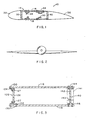
- Figure 1 is an elevation in section of an airplane wing showing the box-like beam strength structure members in a schematic sense.
- Figure 2 is an elevation view of an airplane viewed from the front schematically illustrating the wing and some curvature therefor in a somewhat exaggerated form.
- Figure 3 is another elevation in section of the box-like wing beam structure showing different spar arrangements.
- Figure 4 is a graph showing age forming response (part radius versus tool radius) for the invention and 2324-T39.
- Figure 5 is a graph showing fatigue comparison (double open hole fatigue test).
- Figure 6 is a graph showing fatigue crack growth rate comparison.
- Figure 7 is a graph comparing typical toughness and minimum yield strength characteristics of the invention and several plate products.
- Figure 1 there is shown a rough schematic illustrating a large wing structure 10 including the box member 14 comprising an upper wing skin 16 and, spaced apart therefrom, a lower wing skin 18 and end members or spars 20 and 40 extending between the wing skin members 16 and 18 to close the box member. Included on the inside surfaces of the upper and lower wing skins are stringers 24, 26 and 30 riveted to the inside surfaces of the wing skins, there being different stringer shapes shown for purposes of illustration, it being remembered at all times that Figure 1 is a rough schematic and not a scale or detail of a commercial jet aircraft wing.
- wing skin and stiffener stringer sections can constitute an integrally stiffened panel made from relatively thick plate by operations comprising machining and possibly age forming or other shaping techniques.
- end members 20 and 40, on one hand, and the upper and lower wing skins, on the other hand, is just shown schematically, there being numerous ways to bridge or connect those members. Ahead of the forward box member 20 is the leading part of the wing 32 shown schematically and aft or to the rearward is the rear part of the wing 36, also shown schematically.
- Each part, the forward part and the aft part, can contain numerous control and other parts which can be attached to the box 14.
- the thickness of the upper wing skin 16 and the lower wing skin 18 is diminished proceeding further outwardly from the fuselage. That is, the wing skins are thicker closer to the fuselage and thinner closer to the wing tip.
- the upper wing skin and lower wing skin converge toward the wing tip and can be curved going from the hull of the airplane out to the wing tip.
- This structure also enhances strength and illustrates some of the forming that is typically applied to the upper and lower wing skins such that performing this forming operation during artificial aging is a desirable feature if the alloy permits such, that is, if the alloy predictably and consistently responds in a repeatable way to attempt to age form it.
- upper wing skin 116 and spaced apart lower wing skin 118 are connected or bridged by end member spars 120 and 140 to make a rigid box-like structure.
- end member spars 120 and 140 One way to make an end member-skin connection is shown in the left-hand side of Figure 3 wherein plate-like member 126 is joined by rivets 127 to "L" section member 124 or "T” section member 122 which, in turn, are joined to the skin members by rivets 130.
- This arrangement is very effective but uses many rivets and adds weight over the more simple monolithic or integral spar member 140 shown on the right-hand side of Figure 3 which avoids the extra weight of the rivet site overlap between web plate 126 and members 124 and 122.
- the spar member 140 includes a web portion 142 and integral upper flange portion 144 and lower flange portion 146. Since the upper and lower wing skins 116 and 118 converge toward the wing tip, the vertical length of web portion 142 is greater close to the hull and considerably less near the wing tip and also, since that convergence can be curved, as shown in Figure 2, the height of web portion 142 can diminish in going toward the wing tip in a non-linear manner.
- the web 142 or either or both flange portions 144 or 146 can include thicker portions or boss portions for mounting attachments such as ancillary structures, hydraulic members or various other attachments.
- Integral spar member 140 can be machined or otherwise made or shaped (machining is currently used and is presently preferred) from a larger section of metal 141 (shown in phantom in Figure 3) and that metal 141 can be rolled plate that is thick enough to provide the upper and lower flange portions 144 and 146. That is, dimension 143 corresponds to the short transverse direction (across the thickness) of the rolled plate. That thickness typically can range from about 76 to 203 mm (3 inches to 8 inches) or possibly more, and typically is within 89 or 102 to 152 mm (31 ⁇ 2 or 4 inches to 6 inches).
- properties of concern include strength, both in compression for the upper wing skin region (when in flight), such as upper flange 144 portion, and in tension for the lower wing skin region (when in flight), such as lower flange 146 portion, together with toughness and corrosion resistance, for example, stress corrosion cracking resistance.
- toughness can be less in thicker sections (or metal machined from thick stock) than in metal rolled or worked into thinner stock, and it is desirable for an integral wing spar that good toughness be achieved in relatively thin sections such as web and flange portions 142 and 144 and 146 that are machined from thick stock 141.
- the flange portions of integral spar are riveted or connected to the spaced apart upper and lower wing skins and the spar bridges or connects across the distance the skins are spaced apart. This closes the box-like structure comprising the wing skins and spar members to provide a box-like beam structure to the wing.
- the upper wing skin may be made of the alloys described earlier for that purpose or other alloys.
- the upper wing skin of the claimed airplane wing is made of alloy 7055 and consists of 7.6 to 8.4% zinc, 1.8 to 2.2% magnesium, 2.1 to 2.6% copper, and at least one element present in an amount not exceeding 0.5%, said element selected from Zr, V and Hf, the balance substantially aluminum and incidental elements and impurities.
- the combined total volume percent of insoluble and soluble constituents is kept relatively low, for instance not over 1.5 vol.%, preferably not over 1 vol.%.
- the invention alloy is preferably made into a product, suitably an ingot derived product, suitable for hot rolling.
- a product suitably an ingot derived product, suitable for hot rolling.
- large ingots can be semicontinuously cast of the aforesaid composition and then can be scalped or machined to remove surface imperfections as needed or required to provide a good rolling surface. It is possible to cast an ingot of such quality surface that scalping or machining is not required, but in many cases it is preferred and recommended to scalp the ingot for hot rolling.
- the ingot may then be preheated to homogenize and solutionize its interior structure and a suitable preheat treatment is to heat to a relatively high temperature for this type of composition, such as 482°C (900°F).
- a first lesser temperature level such as heating above 427°C (800°F), for instance about 438°C (820°F) or above, or 454°C (850°F) or above, preferably 460°C (860°F) or more, for instance around 466°C (870°F) or more, and hold the ingot at about that temperature or temperatures for a significant time, for instance, 3 or 4 hours.
- a first lesser temperature level such as heating above 427°C (800°F), for instance about 438°C (820°F) or above, or 454°C (850°F) or above, preferably 460°C (860°F) or more, for instance around 466°C (870°F) or more, and hold the ingot at about that temperature or temperatures for a significant time, for instance, 3 or 4 hours.
- the ingot is heated the rest of the way up to a temperature of around 477°C or 482°C (890°F or 900°F) or possibly more for another hold time of a few hours
- homogenizing be conducted at cumulative hold times in the neighborhood of 4 to 20 hours or more, the homogenizing temperatures referring to temperatures above 438°C (820°F). That is, the cumulative hold time at temperatures above 438°C (820°F) should be at least 4 hours and preferably more, for instance 8 to 20 or 24 hours.
- the ingot is then hot rolled and it is desirable to achieve an unrecrystallized grain structure in the rolled plate product.
- the ingot for hot rolling can exit the furnace at a temperature substantially above 454°C (850°F), for instance around 466°C or 468°C (870 or 875°F) or possibly more, and the rolling operation is carried out at temperatures above 413°C (775°F), or better yet, above 427°C (800°F), for instance around 432°C or 441°C (810 or 825°F).
- the desired thicknesses for the hot rolled plate for lower wing skin metal are generally within around from about 8.9 or 10.2 or 11.4 or 12.7 to about 48.3 or 50.8 or 55.9 mm (0.35 or 0.4 or 0.45 or 0.5 to about 1.9 or 2 or 2.2 inches), preferably within around 22.9 or 25.4 to about 50.8 or 53.3 mm (0.9 or 1 to about 2 or 2.1 inches).
- Plate intended to be machined into integral spars such as 140 can range from about 25.4 or 50.8 mm to about 203 or 229 mm (1 or 2 inches to about 8 or 9 inche) or possibly more.
- This plate typically can range from around 50.8 to 101.6 mm (2 to 4 inches) thick for relatively smaller aircraft similar in size to Boeing 737, up to thicker plate of 101.6 or 127 to 203 mm (4 or 5 inches to 8 inches) or so thick.
- other applications can include forgings and extrusions.
- the alloy is extruded within around 316° to 399°C (600° to 750°F), for instance, at around 371°C (700°F), and preferably includes a reduction in cross-sectional area (extrusion ratio) of about 10:1.
- Forging can be used for parts such as wheels.
- the hot rolled plate or other wrought product is solution heat treated (SHT) by heating to one or more temperatures within around 449° or 454°C to about 471° or 482°C (840 or 850°F to about 880 or 900°F) to take substantial portions, preferably all or substantially all, of the soluble zinc, magnesium and copper into solution, it being again understood that with physical processes which are not always perfect, probably every last vestige of these main alloying ingredients may not be fully dissolved during the SHT (solutionizing). After heating to the elevated temperature as just described, the product should be rapidly cooled or quenched to complete the solution heat treating procedure.
- SHT solution heat treated
- Such cooling is typically accomplished preferably either by immersion in a suitably sized tank of cold water or by water sprays, although air chilling might be usable as supplementary or substitute cooling means for some cooling.
- certain products may need to be cold worked, such as by stretching, so as to relieve internal stresses or straighten the product, even possibly in some cases, to further strengthen the plate product.
- the plate may be stretched 1 or 11 ⁇ 2 or possibly 2% or 3% or more, or otherwise cold worked a generally equivalent amount.
- a solution heat treated (and quenched) product, with or without cold working is then considered to be in a precipitation-hardenable condition, or ready for artificial aging according to preferred artificial aging methods as herein described or other artificial aging techniques.
- solution heat treat unless indicated otherwise, shall be meant to include quenching.
- the plate product After rapidly quenching, and cold working if desired, the plate product is artificially aged by heating to an appropriate temperature to improve strength and other properties.
- the precipitation hardenable plate alloy product is subjected to two main aging steps, phases or treatments, although clear lines of demarcation may not exist between each step or phase. It is generally known that ramping up to and/or down from a given or target treatment temperature, in itself, can produce precipitation (aging) effects which can, and often need to be, taken into account by integrating such ramping conditions and their precipitation hardening effects into the total aging treatment. Such integration was described in greater detail in U.S. Patent 3,645,804 to Ponchel.
- two or three phases for thermally treating the plate product according to the aging practice may be effected in a single, programmable furnace.
- each stage step or phase
- each stage will be more fully described as a distinct operation hereafter. It is believed that the first stage (lower temperature) serves to precipitation harden the alloy product and the second (higher temperature) stage uses one or more elevated temperatures for increasing the resistance to corrosion, such as exfoliation or stress corrosion cracking, and can still further strengthen the alloy.
- a three-stage or step treatment can be employed wherein following the second higher temperature treatment a third treatment at one or more temperatures lower than the higher temperatures used in the second treatment are employed, and this stage can further increase the strength or other properties of the product.
- a third treatment at one or more temperatures lower than the higher temperatures used in the second treatment are employed, and this stage can further increase the strength or other properties of the product.
- the three-stage or phase temperature treatments are described in more detail in the aforesaid U.S. Patents 4,863,528, 4,832,758, 4,477,292 and 5,108,520.
- Still another artificial aging treatment could use a single principal aging stage such as heating to within about 132° or 138°C to about 149° or 154°C (about 270° or 280°F to around 300° or 310°F).
- Some useful artificial aging treatments for practice of the invention include the following:
- Age forming promises a lower manufacturing cost while allowing more complex wing shapes to be formed.
- the part is constrained in a die at an elevated temperature usually between about 121°C and about 204°C (250°F and about 400°F) for several to tens of hours, and desired contours are accomplished through stress relaxation.
- an elevated temperature usually between about 121°C and about 204°C (250°F and about 400°F) for several to tens of hours, and desired contours are accomplished through stress relaxation.
- a higher temperature artificial aging treatment such as a treatment above 160°C (320°F)
- the metal can be formed or deformed into a desired shape.
- the deformations envisioned are relatively simple such as including a very mild curvature across the width of a plate member (such as wing skin members 18 or 16 in Figure 1) together with a mild curvature along the length of a plate such as 18 as is generally illustrated in somewhat exaggerated form in Figure 2 which shows a curvature along the length of the upper and lower wing surfaces. It can be desirable to achieve the formation of these mild curvature conditions during the artificial aging treatment, especially during the higher temperature artificial aging temperature.
- the plate material is heated within around 149° to 204°C (300 to 400°F), for instance around 166° C (330°F), and typically can be placed upon a convex form and loaded by clamping or load application at opposite edges of the plate.
- the plate more or less assumes the contour of the form over a relatively brief period of time but upon cooling springs back a little when the force or load is removed.
- the expected springback is compensated for in designing the curvature or contour of the form which is slightly exaggerated with respect to the desired forming of the plate to compensate for springback.
- An artificial aging treatment step or procedure such as a low temperature aging at around 121°C (250°F) can follow age forming, if desired, or the age forming can be performed at a temperature such as 121°C (250°F) following aging at a higher temperature such as 166°C (330°F).
- the plate member can be machined, for instance, such as by tapering the plate such that the portion intended to be closer to the fuselage is thicker and the portion closest to the wing tip is thinner. Additional machining or other shaping operations, if desired, can also be performed either before or after this age forming treatment.
- the high capacity aircraft may require a relatively thicker plate and a higher level of forming than previously used on a large scale.
- the lower wing cover material for the last few generations of modern commercial jetliners has been generally from the 2X24 alloy family in the naturally aged tempers such as T351 or T39.
- One presently employed product is 2324-T39.
- the invention alloy is preferably in the artificially aged tempers, such as T6-type tempers or preferably T7-type tempers, such as T7651 or T7751.
- the artificial aging treatment can be simultaneously accomplished during age forming without causing-any degradation to its desirable properties.
- the part radius would be equal to the tool radius.
- This condition is illustrated in Figure 4 by the solid line in the plot labeled as "ideal forming". Practically, there will normally be some finite amount of springback.
- the dashed line with filled triangles represents the age forming response of the 2324-T39 alloy showing the effect of springback. Plate of 2324-T39 is commercially used for lower wing skins and is recognized as a good basis of comparison.
- the 2324-T39 alloy was tested under a given set of conditions to minimize the effects of thermal exposure on its final material properties so as to preserve the desired characteristics of the T39 temper for this alloy, but this inherently adversely affects age forming.
- the invention alloy age formed during artificial aging treatments to produce the T7-type tempers is represented by the open circles. It shows equal or less springback, and therefore, better age formability than 2324-T39 for the limited conditions evaluated, and is capable of achieving the desired material properties.
- the strength of plate produced in accordance with the invention is highly useful for lower wing skins.
- the longitudinal ultimate or tensile strength for sheet and thin plate [not over about 64mm (21 ⁇ 2 inches) thick] is typically around 552 to 579 MPa (80 to 84 ksi) or more, and the minimum longitudinal ultimate or tensile strength can be specified at about 570, preferably 538, or more preferably 565 MPa (74, preferably 78, or more preferably 82 ksi) in stronger tempers.
- the typical long transverse ultimate strength is around 545 to 572 MPa (79 to 83 ksi) or more, and a minimum long transverse ultimate or tensile strength can be about 503 or 531 or more, or more preferably 552 or 559 MPa (73 or 77 or more, or more preferably 80 or 81 ksi).
- the tension yield strength in the longitudinal direction is typically around 503 or 510 to 538 or 552 MPa (73 or 74 to 78 or 80 ksi) and minimum longitudinal tension yield strength levels can be about 455 or 462 or 490 MPa (66 or 67 or 71 ksi), or more preferably 517 MPa (75 ksi).
- Long transverse tension yield strength is typically about 503 or 517 MPa (73 or 75 ksi) and minimum long transverse tension yield strength levels can be about 448 or 455 or 483 MPa (65 or 66 or 70 ksi), more preferably 503 or 510 MPa (73 or 74 ksi) in stronger tempers.
- T6 temper material which is aged at or around the so-called peak strength of an alloy exhibits high strength but can also exhibit corrosion resistance, including stress corrosion cracking resistance levels of less than some other tempers.
- T76 temper is often produced by artificially aging beyond a T6 level (relatively slight overaging) to produce a strength level that while less than T6 is somewhat comparable thereto, but T76 material has somewhat better corrosion resistance than T6-type tempers.
- T77 temper can be produced by the three-stage or three-phase treatments described earlier and has a strength level equivalent to or greater than 176 temper.
- T74 temper is artificially aged more than T76 or T77 and has a lower strength level but increased resistance to stress corrosion cracking.
- the temper influences the strength of a particular product in that overaged tempers typically have less strength than peak strength aged tempers but tend to compensate for the strength loss by having better corrosion resistance.
- a T76 material will have a decrease from a T6 temper material of about 5% in strength, whereas a T74 or T73 material will respectively reflect decreases of about 7 and 10% from the T6 or peak strength condition. This is just a general guide and is not necessarily intended to be precise or definitive.
- Another aspect affecting strength is the thickness of the material in that as a general matter thicker material suffers a decrease in strength and toughness in comparison with a thinner material. For instance, comparing a plate of about 30.5 mm (1.2 inches) versus a plate of about 127mm (5 inches) may show a 28 MPa (4 ksi) reduction in yield strength for the 127mm (5-inch) plate and some toughness reduction such as about 5.5 MPa ⁇ m (5 ksi ⁇ inch).
- such can refer to a level at which specifications for purchasing or designating materials can be written or a level at which a material can be guaranteed or a level that an airframe builder (subject to safety factor) can rely on in design. In some cases, it can have a statistical basis wherein 99% of the product conforms or is expected to conform with 95% confidence using standard statistical methods.
- Fracture toughness is an important property to airframe designers, particularly if good toughness can be combined with good strength.
- the tensile strength, or ability to sustain load without fracturing, of a structural component under a tensile load can be defined as the load divided by the area of the smallest section of the component perpendicular to the tensile load (net section stress).
- the strength of the section is readily related to the breaking or tensile strength of a smooth tensile coupon. This is how tension testing is done.
- the strength of a structural component depends on the length of the crack, the geometry of the structural component, and a property of the material known as the fracture toughness. Fracture toughness can be thought of as the resistance of a material to the harmful or even catastrophic propagation of a crack under a load.
- Fracture toughness can be measured in several ways.
- One way is to load in tension a test coupon containing a crack.
- the load required to fracture the test coupon divided by its net section area (the cross-sectional area less the area containing the crack) is known as the residual strength with units of MPa (ksi) (thousand pounds force per square inch).
- MPa ksi
- the residual strength is a measure of the fracture toughness of the material. Because it is so dependent on strength and specimen geometry, residual strength is usually used as a measure of fracture toughness when other methods are not as useful as desired because of some constraint like size or shape of the available material.
- plane-strain fracture toughness K lc .
- the ASTM has established a standard test using a fatigue pre-cracked compact tension specimen to measure K lc which has the units MPa ⁇ m (ksi ⁇ in). This test is usually used to measure fracture toughness when the material is thick because it is believed to be independent of specimen geometry as long as appropriate standards for width, crack length and thickness are met.
- the symbol K, as used in K lc is referred to as the stress intensity factor.
- Structural components which deform by plane-strain are relatively thick as indicated above.
- Thinner structural components usually deform under plane stress or more usually under a mixed mode condition.
- Measuring fracture toughness under this condition can introduce variables because the number which results from the test depends to some extent on the geometry of the test coupon.
- One test method is to apply a continuously increasing load to a rectangular test coupon containing a crack.
- a plot of stress intensity versus crack extension known as an R-curve (crack resistance curve) can be obtained this way. The load at a particular amount of crack extension based on a 25% secant offset in the load vs.
- fracture toughness is often measured as plane-stress fracture toughness which can be determined from a center cracked tension test.
- the fracture toughness measure uses the maximum load generated on a relatively thin, wide pre-cracked specimen.
- the stress-intensity factor is referred to as plane-stress fracture toughness K c .
- the stress-intensity factor is calculated using the crack length before the load is applied, however, the result of the calculation is known as the apparent fracture toughness, K app , of the material.
- the temperature at which the toughness is measured can be significant. In high altitude flights, the temperature encountered is quite low, for instance, -53.9°C (minus 65°F), and for newer commercial jet aircraft projects, toughness at -53.9°C (minus 65°F) is a significant factor, it being desired that the lower wing material exhibit a toughness K lc level of around 50 MPa ⁇ m (45 ksi ⁇ in) at minus 65°F or, in terms of K R20 , a level of 105 MPa ⁇ m (95 ksi ⁇ in), preferably 110 MPa ⁇ m (100 ksi ⁇ in) or more.
- the toughness of the improved products according to the invention is very high and in some cases may allow the aircraft designer's focus for a material's durability and damage tolerance to emphasize fatigue resistance as well as notch toughness measurement.
- Resistance to cracking by fatigue is a very desirable property.
- the fatigue cracking referred to occurs as a result of repeated loading and unloading cycles, or cycling between a high and a low load such as when a wing moves up and down. This cycling in load can occur during flight due to gusts or other sudden changes in air pressure, or on the ground while the aircraft is taxing.
- Fatigue failures account for a large percentage of failures in aircraft components. These failures are insidious because they can occur under normal operating conditions without excessive overloads, and without warning. Crack evolution is accelerated because material inhomogeneities act as sites for initiation or facilitate linking of smaller cracks. Therefore, process or compositional changes which improve metal quality by reducing the severity or number of harmful inhomogeneities improve fatigue durability.
- Stress life (S-N or S/N) fatigue tests characterize a material resistance to fatigue initiation and small crack growth which comprises a major portion of total fatigue life.
- improvements in S-N fatigue properties may enable a component to operate at higher stresses over its design life or operate at the same stress with increased lifetime.
- the former can translate into significant weight savings by downsizing, or manufacturing cost saving by component or structural simplification. while the latter can translate into fewer inspections and lower support costs.
- the loads during fatigue are below the static ultimate or tensile strength of the material measured in a tensile test and they are typically below the yield strength of the material.
- the fatigue initiation fatigue test is an important indicator for a buried or hidden structural member such as a wing spar which is not readily accessible for visual or other examination to look for cracks or crack starts.
- this type of S-N fatigue testing at a net stress concentration factor K t of 2.5 using double open hole specimens (about 229 mm [9 inches] long by 25.4mm [1 inch] wide by 3.2mm [1/8 inch thick] with two holes 4.75 mm [0.187 inch] diameter along the length pulled axially) with a minimum/maximum stress ratio R of 0.1, the invention demonstrates a marked improvement over 2024-T351, 2324-T39 and 7050-T7451, as shown in Figure 5 which is an S-N fatigue comparison.
- Figure 5 shows that for a given stress level the invention allows for many more cycles and that for a desired number of cycles the invention allows for a higher stress than the other products shown.
- a crack or crack-like defect exists in a structure, repeated cyclic or fatigue loading can cause the crack to grow. This is referred to as fatigue-crack propagation. Propagation of a crack by fatigue may lead to a crack large enough to propagate catastrophically when the combination of crack size and loads are sufficient to exceed the material's fracture toughness. Thus, performance in the resistance of a material to crack propagation by fatigue offers substantial benefits to aerostructure longevity. The slower a crack propagates, the better. A rapidly propagating crack in an airplane structural member can lead to catastrophic failure without adequate time for detection, whereas a slowly propagating crack allows time for detection and corrective action or repair. Hence, a low fatigue crack growth rate is a desirable property.
- the rate at which a crack in a material propagates during cyclic loading is influenced by the length of the crack. Another important factor is the difference between the maximum and the minimum loads between which the structure is cycled.
- One measurement including the effects of crack length and the difference between maximum and minimum loads is called the cyclic stress intensity factor range or ⁇ K, having units of MPa ⁇ m (ksi ⁇ in), similar to the stress intensity factor used to measure fracture toughness.
- the stress intensity factor range ( ⁇ K) is the difference between the stress intensity factors at the maximum and minimum loads.
- Another measure affecting fatigue crack propagation is the ratio between the minimum and the maximum loads during cycling, and this is called the stress ratio and is denoted by R, a ratio of 0.1 meaning that the maximum load is 10 times the minimum load.
- the stress, or load, ratio may be positive or negative or zero. Fatigue crack growth rate testing is typically done in accordance with ASTM E647-88 (and others) well known in the art.
- the fatigue crack propagation rate can be measured for a material using a test coupon containing a crack.
- One such test specimen or coupon is about 305 mm (12 inches) long by 102 mm (4 inches) wide having a notch in its center extending in a cross-wise direction (across the width; normal to the length).
- the notch is about 0.813 mm (0.032 inch) wide and about 5 mm (0.2 inch) long including a 60° bevel at each end of the slot.
- the test coupon is subjected to cyclic loading and the crack grows at the end(s) of the notch. After the crack reaches a predetermined length, the length of the crack is measured periodically.
- the crack growth rate can be calculated for a given increment of crack extension by.
- the crack propagation rate is represented by ⁇ a/ ⁇ N or 'da/dN' and has units of 0.03937Xmm (inches)/cycle.
- the invention products exhibit very good corrosion resistance in addition to the very good strength and toughness and damage tolerance performance.
- the exfoliation corrosion resistance for products in accordance with the invention can be EC or better ("or better" meaning EB or EA or N, that is, better performance in the test) in the EXCO test, typically EB or better, for test specimens taken at either mid-thickness (T/2) or one-tenth of the thickness from the surface (T/10) (T is thickness) or both.
- EXCO testing is known in the art and is described in ASTM G34.
- An EXCO rating of "EC” is considered good corrosion resistance in that it is considered acceptable for some commercial aircraft: "EB” is still better.
- Stress corrosion cracking resistance across the short transverse direction is often considered an important property especially in relatively thick members.
- the stress corrosion cracking resistance for products in accordance with the invention in the short transverse direction can be equivalent to that needed to pass a C-ring or 3.2 mm (1/8-inch) round bar alternate immersion test for 20 days at 172 or 207 MPa (25 or 30 ksi) or more, using test procedures in accordance with ASTM G47 (including ASTM G44 and G38 for C-ring specimens and G49 for 3.2 mm [1/8-inch] bars), said ASTM G47, G44, G49 and G38 all known in the art.
- the plate typically can have an electrical conductivity of 35 or 40, or preferably 40% or more of the International Annealed Copper Standard (IACS).
- IACS International Annealed Copper Standard
- the good exfoliation corrosion resistance of the invention is evidenced by an EXCO rating of "EC" or better, but in some cases other measures of corrosion resistance may be specified or required by airframe builders, such as stress corrosion cracking resistance or electrical conductivity. Satisfying any one or more of these specifications is considered good corrosion resistance.
- UTS refers to ultimate or tensile strength
- YS is yield strength
- K refers to toughness
- S/N refers to fatigue performance.
- SCC stress corrosion cracking stress.
- the lower values for strength can correspond more to lower strength tempers such as T74 (especially for plate) whereas higher minimum strength can correspond more to stronger tempers such as T77 or T6 type tempers, although higher levels are also generally more preferred than lower levels for any temper.
- higher numbers generally simply designate preferred levels, although in any specific product a higher strength level can be accompanied by a lower toughness level than a lower strength product.
- a wing skin being typically 6.35 to 38.1 mm (1/4 to 11 ⁇ 2 inches) thick from one end to another, the production of which would start with an aluminum alloy plate having a length of 30 to 45 m (100 to 150 feet), a width of 203 to 305 (80 to 120 inches), and a thickness of about 19 to 45 mm (3/4 to 1-3/4) inches.
- the wing lower skin can be stiffened by stiffener-type stringers which can be J-shaped, such as stringer 25, or Z- or S-shaped, like stringer 30, or it can be a hat-shaped channel, such as 26 shown in Figure 1 for the upper wing skin, or any other shape that can be attached to the wing skin 18 and reinforce its stiffness while not adding a lot of weight While in some cases it is preferred for manufacturing economies to separately fasten stringers such as those shown in Figure 1, such can be machined from a much thicker plate by the removal of the metal between the stiffener geometries, leaving only the stiffener shapes integral with the main wing skin thickness 18, thus eliminating all the rivets. Also the invention has been described in terms of thick plate for machining wing spar members as explained above, the spar member generally corresponding in length to the wing skin material.
- the homogenization included heating to about 471°C (880°F) for a little over 4 hours followed by slowly heating up to a temperature of about 482°C (900°F) holding at 482°C (900°F) for a little over 24 hours.
- the plate was hot rolled at relatively high temperatures to produce plate about 30.5 mm (1.2 inches) thick.
- the high rolling temperatures favor an unrecrystallized condition in the plate after subsequent heat treatment.
- plastic deformation such as rolling, some energy is stored in the deformed metal. Nucleation and growth of new grains may take place during the hot rolling process or during subsequent annealing (or during solution heat treating) at the expense of the deformed matrix. These nuclei are strain-free and are completely or partially surrounded by high-angle grain boundaries.
- unrecrystallized used herein, such means that the plate is preferably 85 to 100% unrecrystallized, or at least 60% of the entire thickness of the plate product is unrecrystallized.
- the desirable "unrecrystallized" grain structure is promoted by minimizing the stored energy of deformation through use of high hot rolling temperature, preferably above 413°C (775°F) or 427°C (800°F). Further, the homogenization treatment described earlier also is designed to cause the precipitation of a fine distribution of dispersoids of ZrAl 3 . These dispersoids pin the migrating grain boundaries during annealing or solution heat treating, and help promote an unrecrystallized grain structure.
- the plate is then solution heat treated to about 482°C (900°F) for about one hour, after which the hot plate is immersed in cold water quenching. The plate was stretched approximately 2% to relieve internal stress and quench distortion and then artificially aged.
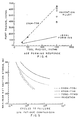
- Figure 7 is a graph showing the performance of the invention plate (one inch thick) in terms of minimum tension yield strength versus typical fracture toughness (L-T direction) K lc in comparison with several other commercial one-inch thick aluminum plate products.
- Table 4 correlates the point designations in Figure 7 with the commercial products they designate.
- the plate members used for the upper and lower wing skins are hot rolled, solution heat treated and quenched.
- the plate is then cut or machined, or both, into a desired shape.
- wing skin is tapered to be thicker at the end closer to the fuselage than at the end further away from the fuselage, and that tapering is typically accomplished by machining.
- the age forming can be carried out after the tapering operation, although it is possible to perform the tapering after an age forming operation which shapes the plate to conform to the desired profile.
- the plate is then artificially aged to a desired temper.
- the extruded or rolled stringers are then attached to the surfaces of the wing skin, specifically the inside surfaces that are not seen from the outside of the airplane.
- the stringers may be extruded or rolled or otherwise made into the elongate shapes as generally shown in Figure 1. If the wing skin plate is bowed, the stringers should also be bowed before joining to the plate.
- the stringers are affixed to the plate normally by mechanical fasteners, typically rivets.
- the plate be made from an alloy in accordance with the invention and that the lower wing skin stringers also be made with an alloy in accordance with the invention.
- one or both end members, or spars are made or shaped, typically by operations comprising machining, from thick plate made in accordance with the invention and fastened to the upper and lower wing skin members, as shown in Figure 3, right side, to make the wing structure "box".
- a preferred embodiment includes making the upper wing skin member from an alloy containing about 7.6 to 8.4% zinc, about 1.8 to 2.2% magnesium, about 2.1 to 2.6% copper and one or more of Zr, V or Hf, present up to 0.5%, preferably Zr, and making one or more spar members in accordance with the invention.
- the lower wing skin is also preferably in accordance with the invention but could be a quality 2XXX type alloy product if desired.
- Fuel tank or other provisions can be placed inside the wing member if it is a box-type member as shown in Figure 1.
Landscapes
- Engineering & Computer Science (AREA)
- Chemical & Material Sciences (AREA)
- Mechanical Engineering (AREA)
- Organic Chemistry (AREA)
- Materials Engineering (AREA)
- Metallurgy (AREA)
- Aviation & Aerospace Engineering (AREA)
- Physics & Mathematics (AREA)
- Thermal Sciences (AREA)
- Crystallography & Structural Chemistry (AREA)
- Pressure Welding/Diffusion-Bonding (AREA)
- Metal Rolling (AREA)
- Contacts (AREA)
- Eyeglasses (AREA)
- Prostheses (AREA)
Abstract
Description
- The invention pertains to an airplane wing comprising a lower wing skin comprising an aluminum alloy material and its manufacture.
- There are numerous commercial jet aircraft of various sizes including the large "jumbo jet" aircraft, such as the Boeing 747 and the McDonnell Douglas MD11 and the Lockheed L1011. In going to a still larger aircraft, such as a 600-passenger aircraft envisioned for the future, the loads on the wing member needed to hold the airplane aloft are heightened some. These large aircraft will carry in the neighborhood of 600 passengers and may include two passenger decks. Whereas a Boeing 747 (one of the largest commercial jet aircraft in use) has an empty weight in the neighborhood of about 180 986 kg (399,000 pounds), it is estimated that the high capacity aircraft envisioned will weigh in the neighborhood of 241 315 kg (532,000 pounds) empty and somewhere around 544 320 kg (1,2000,000 pounds) loaded. High capacity aircraft as used herein refers to an aircraft weighing more than 204 120 kg (450,000 pounds) empty. To heighten efficiency in such an airplane, it would be important to have materials in the wing structures that can support the load of the airplane without themselves becoming too heavy. Aluminum alloys have seen wide use in airplane structural members, including airplane wing structural members, and have an enviable record for dependability and performance. More exotic, composite or other materials can be used for airplane wing-structural members, but are much more costly and can be somewhat less dependable than aluminum alloys.
- In general, the structural core of a large airplane wing can include a box-like structure made up of an upper wing skin, a lower wing skin, and end pieces to close the box-like beam structure. While the upper and lower members are labeled "skin", it is important to appreciate that these are not thin skins such as on the airplane fuselage, but rather, somewhat thick, for instance 12.7mm (a half inch) or more in thickness. In most of the current commercial jet aircraft, the upper wing skin is made of a 7000 Series alloy, currently a 7X50 alloy (7X50 is intended to refer to 7050 and 7150), or more recent alloy 7055. U.S. Patent 3,881,966 describes 7X50 alloys and U.S. Reissue Patent 34,008 describes 7150 alloy used as an upper wing skin on a commercial jet aircraft, and U.S. Patent 5,221,377 describes alloy 7055 and refers to its use in airplane structural members. The upper wing skins were normally in artificially aged tempers such as T6-type or possibly T7-type tempers. U.S. Patents 4,863,528,4,832,758 and 4,477,292, along with U.S. Patent 5,108,520, all describe tempers for 7000 type aluminum alloys, which said temper can be applied to the 7000 Series alloys just mentioned to improve performance.
- In commercial jet aircraft, the lower wing skins have generally been made of
aluminum alloy 2024 or similar products such asalloy 2324 which is included in U.S. Patent 4,294,625. The temper was normally T3-type such as T351 or T39. Temper and alloy designations used herein are generally those used in accordance with the Aluminum Association and are generally recognized in the art and described in the Aluminum Association Standards and Data book. - Both the upper and lower wing skins are often reinforced by stringer members which can have a channel or J-type shape or other shape which are riveted to the inside surfaces to stiffen the wing skins and thereby stiffen the wing box structure. In general, when a commercial jet aircraft is in flight, the upper wing skin is in compression, whereas the lower wing skin is in tension. An exception occurs when the airplane is on the ground where these stresses are reversed but at a much lower-level since at that point the wing outboard of the landing gear pretty much just holds up its own weight. Thus, the more important applications are when the airplane is in flight which places the upper wing skin in compression and the lower wing skin in tension. An exception occurs in certain military airplanes which are designed to utilize their enormous power to weight ratio and are intended to fly upside down, right side up, or any condition between at enormous speeds.
- Because of the particular loading differences encountered in commercial jet airplanes, the alloy selections were, for the most part, as just described. There have been some exceptions in that airplanes such as the Lockheed L1011 included 7075-T76 lower wing skins and stringers and the military KC135 fueler airplane included 7178-T6 lower wing skins and stringers. Another military airplane, the C5A, used 7075-T6 lower wing skins that were integrally stiffened by machining out metal. Military fighter planes such as the F4, F5E, F8, F16 and F18 have included lower wing materials of 7075 alloy or related 7475 alloy (F16 and F18). Nonetheless, over the years the airplane wing box structure has, for the most part, in commercial jet aircraft included a 7000 Series alloy upper wing skin and a lower wing skin of 2000 Series alloy, namely, 2024 or a member of the 2X24 alloy family.
- The important desired properties for a lower wing skin in a high capacity and new commercial passenger jet aircraft include a higher strength than 2X24 alloys, a better fatigue life and improved fracture toughness over 2X24 materials. Because the airplane flies at high altitude where it is cold, fracture toughness at -53.9°C (minus 65°F) has become a concern in new designs. Additional desirable features include age formability whereby the material can be shaped during artificial aging; together with good corrosion performance in the areas of stress corrosion cracking resistance and exfoliation corrosion resistance. Alloys used to date for lower wing skin members in commercial jet aircraft are all lacking in satisfying the needed levels for high capacity aircraft in one or more of these properties.
- In the past, the wing box-like structure was often made from several pieces, as shown in Figure 3, left side, wherein the end member or spar comprised a plate fastened to the upper and lower wing skins by riveting to angle or tee-like members, in turn riveted to the wing skins. Some builders prefer to make the entire end piece or spar as shown on the right side of Figure 3 thus eliminating several rivets and considerable weight by reducing the amount of metal structure. This end piece or spar is made by machining from a thick plate but the plate needs good properties in the transverse directions as well as longitudinal direction.
- EP-A-O 368 005 discloses an unrecrystallised thin gauge flat rolled aluminium alloy for use in aircraft load carrying components such as upper wings, the alloy comprising
- .7-6.9 Zn,
- .9-2.7 Mg,
- .9-2.6 Cu,
- .05-0.15 Zr,
- max. 0.12 Si,
- max. 0.15 Fe,
- max. 0.10 Mn,
- max. 0.06 Ti.
-
- Also disclosed are alloys AA 7050 and AA 7150.
- The alloy is cast, hot worked, solution heat treated, quenched and aged to give a substantially unrecrystallised structure.
- US-A-4 828 631 discloses alloys for use in the aircraft industry containing 5.9 to 8.2 wt. % zinc, 1.5 to 4.0 wt. % magnesium, 1.5 to 3.0 wt. % copper, less than 0.01 wt. % boron not more than 0.04 wt. % chromium, and 0.5 wt. % maximum other alloying elements such as zirconium, manganese, iron, silicon and titanium, with the balance consisting of aluminum. Also disclosed is the alloy into a product of predetermined shape, solution heat treating the shaped product, quenching, and aging the heat treated and quenched product to a temperature of from above 270°F for a period of from 6 to 30 hours.
- Staley, J.T. and Rolf, R.L., 'Trends in alloys for aircraft', Conference: Light Metals Processing and Applications, 29/8/93 - 1/9/93 discloses the use of alloys of the type 7XXX for aircraft components including skins, frames, and stringers for fuselages; leading edges, covers, spars, and stringers for upper and lower wings and empennages, as well as aluminium alloys used as lower wing skin structural members.
- According to the present invention there is provided an airplane wing comprising a lower wing skin structural member comprising an alloy consisting of 5.9 to 6.7% zinc, 1.6 to 1.9% magnesium, 1.8 to 2.4% copper, 0.08 to about 0.15% zirconium, not more than 0.06% silicon, not more than 0.06% iron, not more than 0.11% iron plus silicon, the balance aluminum and unavoidable impurities.
- Preferrably a lower wing skin for a commercial jet aircraft comprises a rolled plate. Composition percent is by weight unless indicated otherwise. This alloy in the form of rolled plates for lower wing skins or in the form of extrusions or rolled product for stringers incorporated into the lower wing structure, and particularly the combination of both, enables the production of an improved wing useful in a high capacity aircraft. Further, the same alloy can be used to machine long tapered spar members for the end pieces of the box-like wing structure from relatively thick plate. Preferred aspects of the lower wing skin as given in the dependent claims.
- Figure 1 is an elevation in section of an airplane wing showing the box-like beam strength structure members in a schematic sense.
- Figure 2 is an elevation view of an airplane viewed from the front schematically illustrating the wing and some curvature therefor in a somewhat exaggerated form.
- Figure 3 is another elevation in section of the box-like wing beam structure showing different spar arrangements.
- Figures 1, 2 and 3 are exaggerated in some respects for schematic, illustrative purposes.
- Figure 4 is a graph showing age forming response (part radius versus tool radius) for the invention and 2324-T39.
- Figure 5 is a graph showing fatigue comparison (double open hole fatigue test).
- Figure 6 is a graph showing fatigue crack growth rate comparison.
- Figure 7 is a graph comparing typical toughness and minimum yield strength characteristics of the invention and several plate products.
- In Figure 1 there is shown a rough schematic illustrating a
large wing structure 10 including thebox member 14 comprising anupper wing skin 16 and, spaced apart therefrom, alower wing skin 18 and end members or spars 20 and 40 extending between thewing skin members stringers end members forward box member 20 is the leading part of thewing 32 shown schematically and aft or to the rearward is the rear part of thewing 36, also shown schematically. Each part, the forward part and the aft part, can contain numerous control and other parts which can be attached to thebox 14. In looking at the box section along various points of the wing length, it is significant that the thickness of theupper wing skin 16 and thelower wing skin 18 is diminished proceeding further outwardly from the fuselage. That is, the wing skins are thicker closer to the fuselage and thinner closer to the wing tip. In addition, as shown in Figure 2, the upper wing skin and lower wing skin converge toward the wing tip and can be curved going from the hull of the airplane out to the wing tip. This structure also enhances strength and illustrates some of the forming that is typically applied to the upper and lower wing skins such that performing this forming operation during artificial aging is a desirable feature if the alloy permits such, that is, if the alloy predictably and consistently responds in a repeatable way to attempt to age form it. - Referring to Figure 3,
upper wing skin 116 and spaced apartlower wing skin 118 are connected or bridged by end member spars 120 and 140 to make a rigid box-like structure. One way to make an end member-skin connection is shown in the left-hand side of Figure 3 wherein plate-like member 126 is joined byrivets 127 to "L"section member 124 or "T"section member 122 which, in turn, are joined to the skin members byrivets 130. This arrangement is very effective but uses many rivets and adds weight over the more simple monolithic orintegral spar member 140 shown on the right-hand side of Figure 3 which avoids the extra weight of the rivet site overlap betweenweb plate 126 andmembers spar member 140 includes aweb portion 142 and integralupper flange portion 144 andlower flange portion 146. Since the upper andlower wing skins web portion 142 is greater close to the hull and considerably less near the wing tip and also, since that convergence can be curved, as shown in Figure 2, the height ofweb portion 142 can diminish in going toward the wing tip in a non-linear manner. Theweb 142 or either or bothflange portions Integral spar member 140 can be machined or otherwise made or shaped (machining is currently used and is presently preferred) from a larger section of metal 141 (shown in phantom in Figure 3) and thatmetal 141 can be rolled plate that is thick enough to provide the upper andlower flange portions dimension 143 corresponds to the short transverse direction (across the thickness) of the rolled plate. That thickness typically can range from about 76 to 203 mm (3 inches to 8 inches) or possibly more, and typically is within 89 or 102 to 152 mm (3½ or 4 inches to 6 inches). For anintegral spar 140, properties of concern include strength, both in compression for the upper wing skin region (when in flight), such asupper flange 144 portion, and in tension for the lower wing skin region (when in flight), such aslower flange 146 portion, together with toughness and corrosion resistance, for example, stress corrosion cracking resistance. In some aluminum alloys, toughness can be less in thicker sections (or metal machined from thick stock) than in metal rolled or worked into thinner stock, and it is desirable for an integral wing spar that good toughness be achieved in relatively thin sections such as web andflange portions thick stock 141. The flange portions of integral spar are riveted or connected to the spaced apart upper and lower wing skins and the spar bridges or connects across the distance the skins are spaced apart. This closes the box-like structure comprising the wing skins and spar members to provide a box-like beam structure to the wing. - In accordance with the invention, the upper wing skin may be made of the alloys described earlier for that purpose or other alloys. Preferably, the upper wing skin of the claimed airplane wing is made of alloy 7055 and consists of 7.6 to 8.4% zinc, 1.8 to 2.2% magnesium, 2.1 to 2.6% copper, and at least one element present in an amount not exceeding 0.5%, said element selected from Zr, V and Hf, the balance substantially aluminum and incidental elements and impurities.
- Preferred embodiments are given in the dependent claims.
- Further, it is preferred that the combined total volume percent of insoluble and soluble constituents is kept relatively low, for instance not over 1.5 vol.%, preferably not over 1 vol.%. Use of relatively high preheat or homogenization and solution heat treat temperatures considering the alloy content aid in this respect, although high temperatures can advise caution to avoid partial melting. Such cautions can include careful heat-up including slow or step-type heating, or both.
- The invention alloy is preferably made into a product, suitably an ingot derived product, suitable for hot rolling. For instance, large ingots can be semicontinuously cast of the aforesaid composition and then can be scalped or machined to remove surface imperfections as needed or required to provide a good rolling surface. It is possible to cast an ingot of such quality surface that scalping or machining is not required, but in many cases it is preferred and recommended to scalp the ingot for hot rolling. The ingot may then be preheated to homogenize and solutionize its interior structure and a suitable preheat treatment is to heat to a relatively high temperature for this type of composition, such as 482°C (900°F). In doing so, it is preferred to heat to a first lesser temperature level such as heating above 427°C (800°F), for instance about 438°C (820°F) or above, or 454°C (850°F) or above, preferably 460°C (860°F) or more, for instance around 466°C (870°F) or more, and hold the ingot at about that temperature or temperatures for a significant time, for instance, 3 or 4 hours. Next the ingot is heated the rest of the way up to a temperature of around 477°C or 482°C (890°F or 900°F) or possibly more for another hold time of a few hours. It is preferred that homogenizing be conducted at cumulative hold times in the neighborhood of 4 to 20 hours or more, the homogenizing temperatures referring to temperatures above 438°C (820°F). That is, the cumulative hold time at temperatures above 438°C (820°F) should be at least 4 hours and preferably more, for instance 8 to 20 or 24 hours.
- The ingot is then hot rolled and it is desirable to achieve an unrecrystallized grain structure in the rolled plate product. Hence, the ingot for hot rolling can exit the furnace at a temperature substantially above 454°C (850°F), for instance around 466°C or 468°C (870 or 875°F) or possibly more, and the rolling operation is carried out at temperatures above 413°C (775°F), or better yet, above 427°C (800°F), for instance around 432°C or 441°C (810 or 825°F). This increases the likelihood of avoiding recrystallization and it is also preferred in some situations to conduct the rolling without a reheating operation by using the power of the rolling mill and heat conservation during rolling to maintain the rolling temperature above a desired minimum, such as 399°C (750°F) or so. Hot rolling is continued, normally in a reversing hot rolling mill, until the desired thickness of the plate is achieved. The desired thicknesses for the hot rolled plate for lower wing skin metal are generally within around from about 8.9 or 10.2 or 11.4 or 12.7 to about 48.3 or 50.8 or 55.9 mm (0.35 or 0.4 or 0.45 or 0.5 to about 1.9 or 2 or 2.2 inches), preferably within around 22.9 or 25.4 to about 50.8 or 53.3 mm (0.9 or 1 to about 2 or 2.1 inches). Plate intended to be machined into integral spars such as 140 can range from about 25.4 or 50.8 mm to about 203 or 229 mm (1 or 2 inches to about 8 or 9 inche) or possibly more. This plate typically can range from around 50.8 to 101.6 mm (2 to 4 inches) thick for relatively smaller aircraft similar in size to Boeing 737, up to thicker plate of 101.6 or 127 to 203 mm (4 or 5 inches to 8 inches) or so thick. In addition to the preferred embodiments of the invention applied to lower wing skin and integral spars, other applications can include forgings and extrusions. In making extrusion, the alloy is extruded within around 316° to 399°C (600° to 750°F), for instance, at around 371°C (700°F), and preferably includes a reduction in cross-sectional area (extrusion ratio) of about 10:1. Forging can be used for parts such as wheels.
- The hot rolled plate or other wrought product is solution heat treated (SHT) by heating to one or more temperatures within around 449° or 454°C to about 471° or 482°C (840 or 850°F to about 880 or 900°F) to take substantial portions, preferably all or substantially all, of the soluble zinc, magnesium and copper into solution, it being again understood that with physical processes which are not always perfect, probably every last vestige of these main alloying ingredients may not be fully dissolved during the SHT (solutionizing). After heating to the elevated temperature as just described, the product should be rapidly cooled or quenched to complete the solution heat treating procedure. Such cooling is typically accomplished preferably either by immersion in a suitably sized tank of cold water or by water sprays, although air chilling might be usable as supplementary or substitute cooling means for some cooling. After quenching, certain products may need to be cold worked, such as by stretching, so as to relieve internal stresses or straighten the product, even possibly in some cases, to further strengthen the plate product. For instance, the plate may be stretched 1 or 1½ or possibly 2% or 3% or more, or otherwise cold worked a generally equivalent amount. A solution heat treated (and quenched) product, with or without cold working, is then considered to be in a precipitation-hardenable condition, or ready for artificial aging according to preferred artificial aging methods as herein described or other artificial aging techniques. As used herein, the term "solution heat treat", unless indicated otherwise, shall be meant to include quenching.
- After rapidly quenching, and cold working if desired, the plate product is artificially aged by heating to an appropriate temperature to improve strength and other properties. In one preferred thermal aging treatment, the precipitation hardenable plate alloy product is subjected to two main aging steps, phases or treatments, although clear lines of demarcation may not exist between each step or phase. It is generally known that ramping up to and/or down from a given or target treatment temperature, in itself, can produce precipitation (aging) effects which can, and often need to be, taken into account by integrating such ramping conditions and their precipitation hardening effects into the total aging treatment. Such integration was described in greater detail in U.S. Patent 3,645,804 to Ponchel. With ramping and its corresponding integration, two or three phases for thermally treating the plate product according to the aging practice may be effected in a single, programmable furnace. For convenience purposes, however, each stage (step or phase) will be more fully described as a distinct operation hereafter. It is believed that the first stage (lower temperature) serves to precipitation harden the alloy product and the second (higher temperature) stage uses one or more elevated temperatures for increasing the resistance to corrosion, such as exfoliation or stress corrosion cracking, and can still further strengthen the alloy. In a second preferred artificial aging treatment, a three-stage or step treatment can be employed wherein following the second higher temperature treatment a third treatment at one or more temperatures lower than the higher temperatures used in the second treatment are employed, and this stage can further increase the strength or other properties of the product. When three artificial aging phases are used, it is usually preferred to control the time for the second (higher) temperature phase so as to allow for further strengthening or beneficiation during the third or lower temperature treatment phase. The three-stage or phase temperature treatments are described in more detail in the aforesaid U.S. Patents 4,863,528, 4,832,758, 4,477,292 and 5,108,520. Still another artificial aging treatment could use a single principal aging stage such as heating to within about 132° or 138°C to about 149° or 154°C (about 270° or 280°F to around 300° or 310°F).
- In some cases, two or three aging phases can be preferred. Some useful artificial aging treatments for practice of the invention include the following:
- 121°C(250°F) for 4 hrs + 163°C (325°F) for 4 hrs;
- 121°C(250°F) for 24 163°C hrs + 163°C (325°F) for 10 hrs;
- 135°C (275°F) for 3 hrs + 168°C (335°F) for 16 hrs. In general, a two-stage artificial aging treatment would include a first stage at temperatures of from about 79 to 149°C (175 to 300°F) or less, preferably around 107 to 135°C or 138°C (225 to 275°F or 280°F), for an amount of time generally inverse to the temperature and ranging from about 1 or 2 hours for 149°C (300°F) and 30 or more hours for temperatures around 93°C (200°F) or less. A preferred treatment is at about 107 to 110°C to about 127 or 132°C (225 or 230°F to about 260 or 270°F) or possibly 135°C (275°F) for around 30 to 3 or 4 hours. A convenient treatment for this condition is 121°C (250°F) for 4 to 30 hours, preferably 8 to 24 hours. For a second higher temperature treatment, the temperature can range from about 149°C (300°F) or a little more to about 177°C (350°F) or perhaps a little higher to about 182 or 188°C (360 or 370°F) or even still higher to temperatures of about 204°C (400°F), although temperatures in the range of about 160 to about 177°C (320 to about 350°F) are preferred from the standpoint of controlling the process, with temperatures in the range of about 160° or 163°C to about 168 or 177°C (320 or 325°F to about 335 or 350°F) being more preferred.
-
- Age forming promises a lower manufacturing cost while allowing more complex wing shapes to be formed. During age forming, the part is constrained in a die at an elevated temperature usually between about 121°C and about 204°C (250°F and about 400°F) for several to tens of hours, and desired contours are accomplished through stress relaxation. Especially during a higher temperature artificial aging treatment, such as a treatment above 160°C (320°F), the metal can be formed or deformed into a desired shape. In general, the deformations envisioned are relatively simple such as including a very mild curvature across the width of a plate member (such as
wing skin members - The lower wing cover material for the last few generations of modern commercial jetliners has been generally from the 2X24 alloy family in the naturally aged tempers such as T351 or T39. One presently employed product is 2324-T39. In using these alloys, the thermal exposure during age forming needs to be minimized in order to retain the desirable material characteristics of the naturally aged tempers. The invention alloy is preferably in the artificially aged tempers, such as T6-type tempers or preferably T7-type tempers, such as T7651 or T7751. As such, the artificial aging treatment can be simultaneously accomplished during age forming without causing-any degradation to its desirable properties.
- Furthermore, the ability of the invention alloy to accomplish desired contours during age forming is either equal to or better than the currently used 2X24 alloys. This is illustrated by the results of an age formability response comparison test, which are presented in Figure 4 which shows a plot of part radius against tool radius.
- If the age formed part conforms exactly to the shape of the die after the age forming cycle, i.e., if there is no "springback", the part radius would be equal to the tool radius. This condition is illustrated in Figure 4 by the solid line in the plot labeled as "ideal forming". Practically, there will normally be some finite amount of springback. The dashed line with filled triangles represents the age forming response of the 2324-T39 alloy showing the effect of springback. Plate of 2324-T39 is commercially used for lower wing skins and is recognized as a good basis of comparison. The 2324-T39 alloy was tested under a given set of conditions to minimize the effects of thermal exposure on its final material properties so as to preserve the desired characteristics of the T39 temper for this alloy, but this inherently adversely affects age forming. The invention alloy age formed during artificial aging treatments to produce the T7-type tempers is represented by the open circles. It shows equal or less springback, and therefore, better age formability than 2324-T39 for the limited conditions evaluated, and is capable of achieving the desired material properties.
- Conforming to the above-identified limitations, including composition and correct processing enhances the production of plate stock having high yield strength together with very good levels of room temperature (RT) and cold temperature (CT) fracture toughness, as well as very good resistance to corrosion. The strength of plate produced in accordance with the invention is highly useful for lower wing skins. The longitudinal ultimate or tensile strength for sheet and thin plate [not over about 64mm (2½ inches) thick] is typically around 552 to 579 MPa (80 to 84 ksi) or more, and the minimum longitudinal ultimate or tensile strength can be specified at about 570, preferably 538, or more preferably 565 MPa (74, preferably 78, or more preferably 82 ksi) in stronger tempers. The typical long transverse ultimate strength is around 545 to 572 MPa (79 to 83 ksi) or more, and a minimum long transverse ultimate or tensile strength can be about 503 or 531 or more, or more preferably 552 or 559 MPa (73 or 77 or more, or more preferably 80 or 81 ksi). The tension yield strength in the longitudinal direction is typically around 503 or 510 to 538 or 552 MPa (73 or 74 to 78 or 80 ksi) and minimum longitudinal tension yield strength levels can be about 455 or 462 or 490 MPa (66 or 67 or 71 ksi), or more preferably 517 MPa (75 ksi). Long transverse tension yield strength is typically about 503 or 517 MPa (73 or 75 ksi) and minimum long transverse tension yield strength levels can be about 448 or 455 or 483 MPa (65 or 66 or 70 ksi), more preferably 503 or 510 MPa (73 or 74 ksi) in stronger tempers.
- The different tempers resulting from different artificial aging treatments will impart different levels of strength and other performance characteristics, especially corrosion related properties, including stress corrosion cracking. T6 temper material which is aged at or around the so-called peak strength of an alloy exhibits high strength but can also exhibit corrosion resistance, including stress corrosion cracking resistance levels of less than some other tempers. T76 temper is often produced by artificially aging beyond a T6 level (relatively slight overaging) to produce a strength level that while less than T6 is somewhat comparable thereto, but T76 material has somewhat better corrosion resistance than T6-type tempers. T77 temper can be produced by the three-stage or three-phase treatments described earlier and has a strength level equivalent to or greater than 176 temper. T74 temper is artificially aged more than T76 or T77 and has a lower strength level but increased resistance to stress corrosion cracking. Hence, when talking about minimum strength levels, it is important to bear in mind that the temper influences the strength of a particular product in that overaged tempers typically have less strength than peak strength aged tempers but tend to compensate for the strength loss by having better corrosion resistance. In general, a T76 material will have a decrease from a T6 temper material of about 5% in strength, whereas a T74 or T73 material will respectively reflect decreases of about 7 and 10% from the T6 or peak strength condition. This is just a general guide and is not necessarily intended to be precise or definitive. Another aspect affecting strength is the thickness of the material in that as a general matter thicker material suffers a decrease in strength and toughness in comparison with a thinner material. For instance, comparing a plate of about 30.5 mm (1.2 inches) versus a plate of about 127mm (5 inches) may show a 28 MPa (4 ksi) reduction in yield strength for the 127mm (5-inch) plate and some toughness reduction such as about 5.5 MPa√m (5 ksi√inch).
- When referring to a minimum (for instance, for strength or toughness), such can refer to a level at which specifications for purchasing or designating materials can be written or a level at which a material can be guaranteed or a level that an airframe builder (subject to safety factor) can rely on in design. In some cases, it can have a statistical basis wherein 99% of the product conforms or is expected to conform with 95% confidence using standard statistical methods.
- Fracture toughness is an important property to airframe designers, particularly if good toughness can be combined with good strength. By way of comparison, the tensile strength, or ability to sustain load without fracturing, of a structural component under a tensile load can be defined as the load divided by the area of the smallest section of the component perpendicular to the tensile load (net section stress). For a simple, straight-sided structure, the strength of the section is readily related to the breaking or tensile strength of a smooth tensile coupon. This is how tension testing is done. However, for a structure containing a crack or crack-like defect, the strength of a structural component depends on the length of the crack, the geometry of the structural component, and a property of the material known as the fracture toughness. Fracture toughness can be thought of as the resistance of a material to the harmful or even catastrophic propagation of a crack under a load.
- Fracture toughness can be measured in several ways. One way is to load in tension a test coupon containing a crack. The load required to fracture the test coupon divided by its net section area (the cross-sectional area less the area containing the crack) is known as the residual strength with units of MPa (ksi) (thousand pounds force per square inch). When the strength of the material as well as the specimen geometry are constant, the residual strength is a measure of the fracture toughness of the material. Because it is so dependent on strength and specimen geometry, residual strength is usually used as a measure of fracture toughness when other methods are not as useful as desired because of some constraint like size or shape of the available material. When the geometry of a structural component is such that it does not deform plastically through the thickness when a tension load is applied (plane-strain deformation), fracture toughness is often measured as plane-strain fracture toughness, Klc. This normally applies to relatively thick products or sections; for
instance 15 or preferably 20 or 25 mm (0.6 or preferably 0.8 or 1 inch) or more. The ASTM has established a standard test using a fatigue pre-cracked compact tension specimen to measure Klc which has the units MPa√m (ksi√in). This test is usually used to measure fracture toughness when the material is thick because it is believed to be independent of specimen geometry as long as appropriate standards for width, crack length and thickness are met. The symbol K, as used in Klc, is referred to as the stress intensity factor. - Structural components which deform by plane-strain are relatively thick as indicated above. Thinner structural components (less than 20 to 25mm [0.8 to 1 inch] thick) usually deform under plane stress or more usually under a mixed mode condition. Measuring fracture toughness under this condition can introduce variables because the number which results from the test depends to some extent on the geometry of the test coupon. One test method is to apply a continuously increasing load to a rectangular test coupon containing a crack. A plot of stress intensity versus crack extension known as an R-curve (crack resistance curve) can be obtained this way. The load at a particular amount of crack extension based on a 25% secant offset in the load vs. crack extension curve and the effective crack length at that load are used to calculate a measure of fracture toughness known as KR25. At a 20% secant, it is known as KR20. It also has the units of ksi√in. ASTM E561 (incorporated in its entirety herein by reference) concerns R-curve determination, and such is generally recognized in the art.
- When the geometry of the alloy product or structural component is such that it permits deformation plastically through its thickness when a tension load is applied, fracture toughness is often measured as plane-stress fracture toughness which can be determined from a center cracked tension test. The fracture toughness measure uses the maximum load generated on a relatively thin, wide pre-cracked specimen. When the crack length at the maximum load is used to calculate the stress-intensity factor at that load, the stress-intensity factor is referred to as plane-stress fracture toughness Kc. When the stress-intensity factor is calculated using the crack length before the load is applied, however, the result of the calculation is known as the apparent fracture toughness, Kapp, of the material. Because the crack length in the calculation of Kc is usually longer, values for Kc are usually higher than Kapp for a given material. Both of these measures of fracture toughness are expressed in the units ksi√in. For tough materials, the numerical values generated by such tests generally increase as the width of the specimen increases or its thickness decreases as is recognized in the art. Unless indicated otherwise herein, plane stress (Kc) values referred to herein refer to 406 mm (16-inch) wide test panels. Those skilled in the art recognize that test results can vary depending on the test panel width, and it is intended to encompass all such tests in referring to toughness. Hence, toughness substantially equivalent to or substantially corresponding to a minimum value for Kc or Kapp in characterizing the invention products, while largely referring to a test with a 406 mm (16-inch) panel, is intended to embrace variations in Kc or Kapp encountered in using different width panels as those skilled in the art will appreciate.
- The temperature at which the toughness is measured can be significant. In high altitude flights, the temperature encountered is quite low, for instance, -53.9°C (minus 65°F), and for newer commercial jet aircraft projects, toughness at -53.9°C (minus 65°F) is a significant factor, it being desired that the lower wing material exhibit a toughness Klc level of around 50 MPa√m (45 ksi√in) at minus 65°F or, in terms of KR20, a level of 105 MPa√m (95 ksi√in), preferably 110 MPa√m (100 ksi√in) or more.
- The toughness of the improved products according to the invention is very high and in some cases may allow the aircraft designer's focus for a material's durability and damage tolerance to emphasize fatigue resistance as well as notch toughness measurement. Resistance to cracking by fatigue is a very desirable property. The fatigue cracking referred to occurs as a result of repeated loading and unloading cycles, or cycling between a high and a low load such as when a wing moves up and down. This cycling in load can occur during flight due to gusts or other sudden changes in air pressure, or on the ground while the aircraft is taxing. Fatigue failures account for a large percentage of failures in aircraft components. These failures are insidious because they can occur under normal operating conditions without excessive overloads, and without warning. Crack evolution is accelerated because material inhomogeneities act as sites for initiation or facilitate linking of smaller cracks. Therefore, process or compositional changes which improve metal quality by reducing the severity or number of harmful inhomogeneities improve fatigue durability.
- Stress life (S-N or S/N) fatigue tests characterize a material resistance to fatigue initiation and small crack growth which comprises a major portion of total fatigue life. Hence, improvements in S-N fatigue properties may enable a component to operate at higher stresses over its design life or operate at the same stress with increased lifetime. The former can translate into significant weight savings by downsizing, or manufacturing cost saving by component or structural simplification. while the latter can translate into fewer inspections and lower support costs. The loads during fatigue are below the static ultimate or tensile strength of the material measured in a tensile test and they are typically below the yield strength of the material. The fatigue initiation fatigue test is an important indicator for a buried or hidden structural member such as a wing spar which is not readily accessible for visual or other examination to look for cracks or crack starts. In this type of S-N fatigue testing at a net stress concentration factor Kt of 2.5 using double open hole specimens (about 229 mm [9 inches] long by 25.4mm [1 inch] wide by 3.2mm [1/8 inch thick] with two holes 4.75 mm [0.187 inch] diameter along the length pulled axially) with a minimum/maximum stress ratio R of 0.1, the invention demonstrates a marked improvement over 2024-T351, 2324-T39 and 7050-T7451, as shown in Figure 5 which is an S-N fatigue comparison. Figure 5 shows that for a given stress level the invention allows for many more cycles and that for a desired number of cycles the invention allows for a higher stress than the other products shown.
- If a crack or crack-like defect exists in a structure, repeated cyclic or fatigue loading can cause the crack to grow. This is referred to as fatigue-crack propagation. Propagation of a crack by fatigue may lead to a crack large enough to propagate catastrophically when the combination of crack size and loads are sufficient to exceed the material's fracture toughness. Thus, performance in the resistance of a material to crack propagation by fatigue offers substantial benefits to aerostructure longevity. The slower a crack propagates, the better. A rapidly propagating crack in an airplane structural member can lead to catastrophic failure without adequate time for detection, whereas a slowly propagating crack allows time for detection and corrective action or repair. Hence, a low fatigue crack growth rate is a desirable property.
- The rate at which a crack in a material propagates during cyclic loading is influenced by the length of the crack. Another important factor is the difference between the maximum and the minimum loads between which the structure is cycled. One measurement including the effects of crack length and the difference between maximum and minimum loads is called the cyclic stress intensity factor range or ΔK, having units of MPa√m (ksi√in), similar to the stress intensity factor used to measure fracture toughness. The stress intensity factor range (ΔK) is the difference between the stress intensity factors at the maximum and minimum loads. Another measure affecting fatigue crack propagation is the ratio between the minimum and the maximum loads during cycling, and this is called the stress ratio and is denoted by R, a ratio of 0.1 meaning that the maximum load is 10 times the minimum load. The stress, or load, ratio may be positive or negative or zero. Fatigue crack growth rate testing is typically done in accordance with ASTM E647-88 (and others) well known in the art.
- The fatigue crack propagation rate can be measured for a material using a test coupon containing a crack. One such test specimen or coupon is about 305 mm (12 inches) long by 102 mm (4 inches) wide having a notch in its center extending in a cross-wise direction (across the width; normal to the length). The notch is about 0.813 mm (0.032 inch) wide and about 5 mm (0.2 inch) long including a 60° bevel at each end of the slot. The test coupon is subjected to cyclic loading and the crack grows at the end(s) of the notch. After the crack reaches a predetermined length, the length of the crack is measured periodically. The crack growth rate can be calculated for a given increment of crack extension by. dividing the change in crack length (called Δa) by the number of loading cycles (ΔN) which resulted in that amount of crack growth. The crack propagation rate is represented by Δa/ΔN or 'da/dN' and has units of 0.03937Xmm (inches)/cycle. The fatigue crack propagation rates of a material can be determined from a center cracked tension panel. In a comparison using R=0.1 tested at a relative humidity over 90% with ΔK ranging from around 4 to 20 or 30, the invention material exhibited relatively good resistance to fatigue crack growth, similar to 2024-T351,2324-T39 and 7050-T7451, as shown in Figure 6. However, the superior performance in S-N fatigue shown in Figure 5 makes the invention material much better suited for a buried or hidden member such as a wing spar.
- The invention products exhibit very good corrosion resistance in addition to the very good strength and toughness and damage tolerance performance.
- The exfoliation corrosion resistance for products in accordance with the invention can be EC or better ("or better" meaning EB or EA or N, that is, better performance in the test) in the EXCO test, typically EB or better, for test specimens taken at either mid-thickness (T/2) or one-tenth of the thickness from the surface (T/10) (T is thickness) or both. EXCO testing is known in the art and is described in ASTM G34. An EXCO rating of "EC" is considered good corrosion resistance in that it is considered acceptable for some commercial aircraft: "EB" is still better.
- Stress corrosion cracking resistance across the short transverse direction is often considered an important property especially in relatively thick members. The stress corrosion cracking resistance for products in accordance with the invention in the short transverse direction can be equivalent to that needed to pass a C-ring or 3.2 mm (1/8-inch) round bar alternate immersion test for 20 days at 172 or 207 MPa (25 or 30 ksi) or more, using test procedures in accordance with ASTM G47 (including ASTM G44 and G38 for C-ring specimens and G49 for 3.2 mm [1/8-inch] bars), said ASTM G47, G44, G49 and G38 all known in the art.
- As a general indicator of exfoliation corrosion and stress corrosion resistance, the plate typically can have an electrical conductivity of 35 or 40, or preferably 40% or more of the International Annealed Copper Standard (IACS).
- Thus, the good exfoliation corrosion resistance of the invention is evidenced by an EXCO rating of "EC" or better, but in some cases other measures of corrosion resistance may be specified or required by airframe builders, such as stress corrosion cracking resistance or electrical conductivity. Satisfying any one or more of these specifications is considered good corrosion resistance.
- Table 1 below lists minimum property levels for different product forms of the invention. UTS refers to ultimate or tensile strength; YS is yield strength; and K refers to toughness. S/N refers to fatigue performance. SCC is stress corrosion cracking stress. In general, but not necessarily in limitation, especially for thick plate, the lower values for strength can correspond more to lower strength tempers such as T74 (especially for plate) whereas higher minimum strength can correspond more to stronger tempers such as T77 or T6 type tempers, although higher levels are also generally more preferred than lower levels for any temper. In the case of toughness and fatigue, higher numbers generally simply designate preferred levels, although in any specific product a higher strength level can be accompanied by a lower toughness level than a lower strength product. In Table 1, property direction is in accordance with convention (e.g. L=longitudinal: LT=long transverse, and so on). Fracture toughness is tested at both 24°C (75°F) and -53.9°C (minus 65°F) in referring to room temperature (RT), such encompasses temperatures associated with ordinary room temperature (for example, temperatures such as around 21 to 27°C [70° to 80°F], typically around 24°C [75°F]).

- The invention has been described in terms of plate which is preferred, but it is believed that other product forms may be able to enjoy the benefits of the invention and Table 1 refers to minimum property levels for extrusions and forgings,
- To this point, the emphasis has been on rolled plate products for die wing skin of a large airplane, a wing skin being typically 6.35 to 38.1 mm (1/4 to 1½ inches) thick from one end to another, the production of which would start with an aluminum alloy plate having a length of 30 to 45 m (100 to 150 feet), a width of 203 to 305 (80 to 120 inches), and a thickness of about 19 to 45 mm (3/4 to 1-3/4) inches. It can be seen (referring again to Figure 1) that the wing lower skin can be stiffened by stiffener-type stringers which can be J-shaped, such as
stringer 25, or Z- or S-shaped, likestringer 30, or it can be a hat-shaped channel, such as 26 shown in Figure 1 for the upper wing skin, or any other shape that can be attached to thewing skin 18 and reinforce its stiffness while not adding a lot of weight While in some cases it is preferred for manufacturing economies to separately fasten stringers such as those shown in Figure 1, such can be machined from a much thicker plate by the removal of the metal between the stiffener geometries, leaving only the stiffener shapes integral with the mainwing skin thickness 18, thus eliminating all the rivets. Also the invention has been described in terms of thick plate for machining wing spar members as explained above, the spar member generally corresponding in length to the wing skin material. - Ingots about 40 to 127 cm (16 inches by 50 inches) in cross section having the following compositions were cast:
Compositions Alloy Si(%) Fe(%) Cu(%) Mg(%) Cr(%) Zn(%) Zr(%) Alloy A (Invention) 0.03 0.03 1.96 1.72 -- 6.37 0.11 Alloy B 0.04 0.03 1.97 2.48 -- 6.58 0.11 7050 0.12 0.15 2.2 2.2 0.04 6.1 within 0.08-0.15 - By "unrecrystallized" used herein, such means that the plate is preferably 85 to 100% unrecrystallized, or at least 60% of the entire thickness of the plate product is unrecrystallized.
- The desirable "unrecrystallized" grain structure is promoted by minimizing the stored energy of deformation through use of high hot rolling temperature, preferably above 413°C (775°F) or 427°C (800°F). Further, the homogenization treatment described earlier also is designed to cause the precipitation of a fine distribution of dispersoids of ZrAl3. These dispersoids pin the migrating grain boundaries during annealing or solution heat treating, and help promote an unrecrystallized grain structure. The plate is then solution heat treated to about 482°C (900°F) for about one hour, after which the hot plate is immersed in cold water quenching. The plate was stretched approximately 2% to relieve internal stress and quench distortion and then artificially aged. The artificial aging treatments employed and the properties measured are indicated in Table 3 below where the superiority of the invention in toughness and strength-toughness property combination along with notched (double open hole) fatigue performance is readily apparent.
Properties Composition Age Treatment Alloy A 24h/250°+10h/325° Alloy B 7050 T7651 24h/250°+10h/325° 24h/250°+20h/325° Strength
L orientationYS, (ksi) MPa (76.2) 525 (82.3) 568 (73.8) 509 (70) 483 UTS, (ksi) MPa (82.1) 566 (88.5) 610 (81.8) 564 (78) 538 Elong, % 13.6 11.8 14.0 -- Strength
LT orientationYS, (ksi) MPa (75.4) 520 (82.1) 566 (69) 476 UTS, (ksi) MPa (81.4) 561 (88.6) 611 (78) 538 Elong, % 13.0 11.0 -- Toughness
KIc, (ksi√in)L-T at (75°F) 24°C (47.5) (26.2) (33.3) (31) L-T at (-65°F) -53.9°C (42.0) (26.9) T-L at (75°F) 24°C (40.7) (24.0) (28) Toughness
Kc,(ksi√in)L-T at (75°F) 24°C (172.9) 190.2 (126.6) 139.3 L-T at (-65°F) -53.9°C (166.4) 183.0 (99.3) 109.2 T-L at (75°F) 24°C (123.9) 136.3 T-L at (-65°F) -53.9°C (79.8) 87.8 Fatigue
S/N, Kt=2.5N at S=(29 ksi) 200 MPa 565.000 145.708 N at S=(31 ksi) 214 MPa 226.000 88,400 N at S=(33 ksi) 228 MPa 70.700 - The aluminium alloy claimed is considered superior when used as a lower wing skin to several alloy-temper combinations including several currently considered useful in structural parts for commercial jet aircraft. Figure 7 is a graph showing the performance of the invention plate (one inch thick) in terms of minimum tension yield strength versus typical fracture toughness (L-T direction) Klc in comparison with several other commercial one-inch thick aluminum plate products. The following Table 4 correlates the point designations in Figure 7 with the commercial products they designate.
Plate Product Symbols in Figure 7 2024-T351 ○ white circle 2324-T39 black circle 7150-T6151 □ white square 7150-T7751 ⋄ white diamond 7050-T7451 X "X" 7050-T7651 + plus sign 7475-T651 Δ white triangle 7475-T7651 □ white square with dot 7475-T7351 ▪ black square 7055-T7751 ◆ black diamond 7010-T7365 ▴ black triangle - In manufacturing the wing for high capacity and other commercial jet aircraft the plate members used for the upper and lower wing skins are hot rolled, solution heat treated and quenched. The plate is then cut or machined, or both, into a desired shape. Normally, wing skin is tapered to be thicker at the end closer to the fuselage than at the end further away from the fuselage, and that tapering is typically accomplished by machining. There is also often a slight bowing of the wing, as shown in Figure 2, which can be accomplished by machining or by age forming. The age forming can be carried out after the tapering operation, although it is possible to perform the tapering after an age forming operation which shapes the plate to conform to the desired profile. The plate is then artificially aged to a desired temper. As just stated, there can be some combination of forming and aging in this sequence of operations. The extruded or rolled stringers are then attached to the surfaces of the wing skin, specifically the inside surfaces that are not seen from the outside of the airplane. The stringers may be extruded or rolled or otherwise made into the elongate shapes as generally shown in Figure 1. If the wing skin plate is bowed, the stringers should also be bowed before joining to the plate. The stringers are affixed to the plate normally by mechanical fasteners, typically rivets. In accordance with the invention, for the lower wing skin, it is preferred that the plate be made from an alloy in accordance with the invention and that the lower wing skin stringers also be made with an alloy in accordance with the invention. The skins for the upper and lower wing box members are then assembled with the
end pieces - It can be of advantage in some cases to clad plate or sheet in accordance with the invention to enhance some corrosion resistance aspects in accordance with principles recognized in the art.
- While some emphasis is placed on high capacity airplanes, and lower wing skins for such, it is believed the invention also applies to other commercial airplanes as well.
- Unless indicated otherwise, as used throughout this description of the invention, the following definitions shall apply:
- a. The term "ksi" means kilopounds per square inch.
- b. The term "minimum strength" or a minimum for another property or a maximum for a property shall mean the level at which 99% of the product is expected to conform with 95% confidence using standard statistical methods.
- c. The term "ingot-derived" means solidified from liquid metal by a known or subsequently developed casting processes and includes, but is not limited to, direct chill (DC) continuous casting, electromagnetic continuous (EMC) casting, and variations thereof, as well as truly continuous slab and other casting techniques.
- d. The term "7XXX" or "7000 Series" when referring to alloys shall mean structural aluminum alloys containing zinc as their alloying element present in the greatest weight percent as defined by the Aluminum Association.
- e. The term "2XXX" or "2000 Series" when referring to alloys shall mean structural aluminum alloys containing copper as their alloying element present in the greatest weight percent as defined by the Aluminum Association . In stating a numerical range or a minimum or a maximum for an element of a composition or a temperature, time or other process matter or a property or an extent of improvement or any other matter herein, and apart from and in addition to the customary rules for rounding off numbers, such is intended to specifically designate and disclose each number, including each fraction and/or decimal, (i) within and between the stated minimum and maximum for a range, or (ii) at and above a stated minimum, or (iii) at and below a stated maximum. For example, a range of 6 to 6.7% zinc expressly specifically discloses zinc contents of 6.1, 6.2, 6.3%...and so on, up to about 6.7% zinc. Similarly, herein disclosing artificial aging to one or more temperatures between about 148.9° and 204.4°C (300° and 400°F) specifically discloses 149.4°, 150°...157.2, 157.8°C (301°, 302°...315°, 316°F)....and so on, up to the stated maximum. Designating up to 0.06% or 0.06% maximum discloses 0.01, 0.02. . .---up to 0.06%.
-
Claims (33)
- An airplane wing comprising a lower wing skin structural member comprising an alloy consisting of 5.9 to 6.7% zinc, 1.6 to 1.9% magnesium, 1.8 to 2.4% copper, 0.08 to 0.15% zirconium, not more than 0.06% silicon, not more than 0.06% iron, not more than 0.11% iron plus silicon, the balance aluminum and unavoidable impurities.
- A wing according to claim 1, in which said lower wing skin structural member comprises rolled plate alloy.
- A wing according to claim 1, wherein the wing also comprises an upper wing skin structural member comprising a hot rolled, solution heat treated and artificially aged alloy consisting of 7.6 to 8.4% zinc, 1.8 to 2.2% magnesium, 2.1 to 2.6% copper, and at least one element present in an amount not exceeding 0.5%, said element selected from zirconium, vanadium and hafnium, the balance aluminum and unavoidable impurities.
- A wing according to claim 3, wherein the upper and lower wing skin structural members are connected by one or more spar members machined from rolled plate of an alloy as defined in claim 1.
- A method of producing airplane lower wing skin structural members for a commercial jet aircraft comprising forming said member from an alloy consisting of 5.9 to 6.7% zinc, 1.6 to 1.9% magnesium, 1.8 to 2.4% copper, 0.08 to 0.15% zirconium, not more than 0.06% silicon, not more than 0.06% iron, not more than 0.11% iron plus silicon, the balance aluminum and unavoidable impurities.
- A method according to claim 5, which comprises producing a lower wing skin structural member by providing a body of alloy as defined in claim 5;
homogenizing said alloy by heating from 399° to 477°C (750 to 890°F) and further heating from 410° to 488°C (770°F to 910°F);
hot rolling said alloy at temperature above 399°C (750°F);
solution heat treating said alloy at a temperature of at least 471°C (880°F);
quenching said alloy;
stretching said alloy at least about 1%;
artificially aging said alloy by heating from 79° to 143°C (175° to 290°F) and heating from 149° to 177°C (300° to 350°F). - A method according to claim 5, wherein an aluminum alloy plate member is made into a lower wing skin structural member, said method including shaping said plate member for said wing structural member and fastening thereto elongate stringers, and wherein said plate member and said stringer members comprise aluminum alloys wherein each such alloy is as defined in claim 5.
- A method according to claim 5, of making wing structural members for a commercial aircraft wherein an upper wing skin member and a spaced apart therefrom lower wing skin member are arranged to cooperate in providing structural strength to said wing member and wherein at least said lower wing skin member has attached thereto elongate stringers, wherein the metal for said lower wing skin member is provided as a wrought aluminum mill rolled plate product comprising an aluminum alloy as defined in claim 5, and wherein the metal for said elongate stringer members is provided as a wrought aluminum mill product comprising an alloy as defined in claim 5.
- A method according to claim 5, of producing a rolled plate for a wing spar structural member for a commercial jet aircraft comprising providing a body of alloy as defined in claim 5;
homogenizing said alloy by heating from 399 to 477°C (750° to 890°F) and further heating from 410 to 488°C (770°F to 910°F);
hot rolling said alloy at temperature above 399°C (750°F);
solution heat treating said alloy at a temperature of at least 471°C (880°F); quenching said alloy;
artificially aging said alloy by heating from 79° to 143°C (175° to 290°F) and heating from 149° to 177°C (300° to 400°F). - A method according to claim 5, wherein a thick aluminum alloy plate member is made into,a wing spar structural member, said method including shaping said plate member to a shape for said wing structural spar member, wherein said plate member comprises an aluminum alloy as defined in claim 5.
- A method according to claim 6, which produces a hot rolled plate wherein said plate before or after any shaping has after artificial aging an L yield strength of at least 469 MPa (68 ksi), an LT yield strength of at least 462 MPa (67 ksi), an L-T fracture toughness Klc at RT of at least 37.4 MPA
- A method according to claim 7, wherein said plate before or after any shaping has after artificial aging an L yield strength of at least 490 MPA (71 ksi), an LT yield strength of at least 483 MPA (70 ksi), an L-T fracture toughness Klc at RT of at least 46.2 MPA
- A method according to claim 8, wherein said rolled plate product before or after any shaping has after artificial aging an L yield strength of at least 462 MPA (67 ksi), an LT yield strength of at least 455 MPA (66 ksi), an L-T fracture toughness Klc at RT of at least 42.9 MPa
- A method according to claim 9, wherein said plate is at least 76 mm (3 inches) thick and before or after any shaping has after artificial aging an L yield strength of at least 441 MPA (64 ksi), an LT yield strength of at least 434 MPA (63 ksi), an L-T fracture toughness Klc at RT of at least 28.6 MPA
- A method according to claim 9, wherein said plate is at least 76 mm (3 inches) thick and before or after any shaping has after artificial aging an L yield strength of at least 414 MPA (60 ksi), an LT yield strength of at least 407 MPA (59 ksi), an L-T fracture toughness Klc at RT of at least 25.3 MPA
- A method according to claim 9, which includes an additional artificial aging heating from 79 to 143°C (175°F to 290°F) after said heating from 149 to 177°C (300°F to 400°F).
- A method according to claim 10, wherein said plate is at least 64 mm (2 ½ inches) thick and before or after any shaping has after artificial aging an L yield strength of at least 469 MPA (68 ksi), an LT yield strength of at least 462 MPA (67 ksi), an L-T fracture toughness Klc at RT of at least 37.4 MPA
- A method according to claim 7, wherein said plate before or after any shaping has after artificial aging an L yield strength of at least 490 MPA (71 ksi), an LT yield strength of at least 483 MPA (70 ksi), an L-T fracture toughness Klc at RT of at least 42.9 MPA
- A method according to claim 7, wherein said plate as rolled is less than 64 mm (2½ inches) thick and before or after any shaping, has, after artificial aging, an L ultimate strength of at least 538 MPA (78 ksi), an LT ultimate strength of at least 531 MPA (77 ksi), an L-T fracture toughness Klc at RT of at least 46.2 MPA
- A method according to claim 7, wherein said plate as rolled is less than 64 mm (2½ inches) thick and, before or after any shaping, has, after artificial aging, an L yield strength of at least 490 MPA
- A method according to claim 7, wherein said plate as rolled is less than 64 mm (2½ inches) thick and, before or after any shaping, has, after artificial aging, an L yield strength of at least 462 MPa (67 ksi), an LT yield strength of at least 455 MPa (66 ksi), an L-T fracture toughness Klc at RT of at least 137.5 MPA
- A method according to claim 10, wherein said plate as rolled is at least 64 mm (2½ inches) thick and, before or after any shaping, has, after artificial aging, an L yield strength of at least 469 MPa (68 ksi), an LT yield strength of at least 462 MPa (67 ksi), an ST yield strength of at least 421 MPa (61 ksi), an L-T fracture toughness Klc at Rt of at least 34.1 MPA
- A method according to claim 10, wherein said plate as rolled is at least 64 mm (2½ inches) thick and, before or after any shaping, has, after artificial aging, an L ultimate strength of at least 476 MPa (69 ksi), an LT ultimate strength of at least 469 MPa (68 ksi), an ST ultimate strength of at least 441 MPa (64 ksi), an L-T fracture toughness Klc at RT of at least 37.4 MPA
- A method according to claim 10, wherein said plate as rolled is greater than 102 mm (4 inches) thick and, before or after any shaping, has, after artificial aging, an L yield strength of at least 414 MPa (60 ksi), an LT yield strength of at least 407 MPa (59 ksi), an ST yield strength of at least 372 MPa (54 ksi), an L-T fracture toughness Klc at RT of at least 25.3 MPA
- A method according to claim 5, comprising providing a body of alloy as defined in claim 5;
homogenizing said alloy by heating from 399 to 477°C (750° to 890°F) and further heating from 410 to 488°C (770°F to 910°F);
hot working said alloy;
solution heat treating said alloy at a temperature of at least 471°C (880°F);
quenching said alloy;
artificially aging said alloy by heating from 79 to 143°C (175° to 290°F) and heating from 149 to 177°C (300° to 350°F). - A method according to claim 25, wherein said hot working is extrusion.
- A method according to claim 25, wherein said hot working is forging.
- A method according to claim 5, wherein an upper wing skin member and a spaced apart therefrom lower wing skin member are arranged to cooperate in providing structural strength to said wing member and wherein said upper and lower wing skin members are bridged by a spar member shaped from a rolled aluminum plate, wherein the metal for said rolled plate product is provided as an aluminum alloy as defined in claim 5.
- A method according to claim 28, wherein said plate as rolled is at least 64mm (2½ inches) thick and, before or after any shaping, has, after artificial aging, an L yield strength of at least 469 MPa (68 ksi), an LT yield strength of at least 462 MPa (67 ksi), an L-T fracture toughness Klc at RT of at least 34.1 MPA
- A method according to claim 28, wherein said plate as rolled is a least 64mm (2½ inches) thick and, before or after any shaping, has, after artificial aging, an L ultimate strength of at least 476 MPa (69 ksi), an LT ultimate strength of at least 469 MPa (68 ksi), an ST ultimate strength of at least 414 MPa (60 ksi), an L-T fracture toughness Klc at RT of at least 37.4 MPA
- A method according to claim 28, wherein said plate as rolled is greater than 102mm (4 inches) thick and, before or after any shaping, has, after artificial aging, an L yield strength of at least 428 MPa (62 ksi), an LT yield strength of at least 421 MPa (61 ksi), an ST yield strength of at least 372 MPa (54 ksi), an L-T fracture toughness Klc at RT of at least 25.3 MPA
- A method according to claim 5, comprising providing a body of alloy as defined in claim 5;
homogenizing said alloy;
hot rolling said alloy into a plate;
solution heat treating the alloy;
quenching the alloy;
the plate being substantially unrecrystallized and having, after artificial aging, an L yield strength of at least 428 MPa (62 ksi), an LT yield strength of at least 421 MPa (61 ksi), an ST yield strength of at least 37.2 MPa (54 ksi), an L-T fracture toughness Klc at RT of at least 25.3 MPa - A method according to claim 5, wherein an aluminum alloy plate member is made into an aircraft structural member, said method including machining said plate member to a shape for said structural member, wherein said plate member comprises an aluminum alloy as defined in claim 5, said plate being substantially unrecrystallized.
Priority Applications (3)
| Application Number | Priority Date | Filing Date | Title |
|---|---|---|---|
| AT96306602T ATE245207T1 (en) | 1996-09-11 | 1996-09-11 | ALUMINUM ALLOY FOR COMMERCIAL AIRCRAFT WINGS |
| EP96306602A EP0829552B1 (en) | 1996-09-11 | 1996-09-11 | Aluminium alloy products suited for commercial jet aircraft wing members |
| DE69629113T DE69629113T2 (en) | 1996-09-11 | 1996-09-11 | Aluminum alloy for airliner wings |
Applications Claiming Priority (1)
| Application Number | Priority Date | Filing Date | Title |
|---|---|---|---|
| EP96306602A EP0829552B1 (en) | 1996-09-11 | 1996-09-11 | Aluminium alloy products suited for commercial jet aircraft wing members |
Publications (2)
| Publication Number | Publication Date |
|---|---|
| EP0829552A1 EP0829552A1 (en) | 1998-03-18 |
| EP0829552B1 true EP0829552B1 (en) | 2003-07-16 |
Family
ID=8225080
Family Applications (1)
| Application Number | Title | Priority Date | Filing Date |
|---|---|---|---|
| EP96306602A Revoked EP0829552B1 (en) | 1996-09-11 | 1996-09-11 | Aluminium alloy products suited for commercial jet aircraft wing members |
Country Status (3)
| Country | Link |
|---|---|
| EP (1) | EP0829552B1 (en) |
| AT (1) | ATE245207T1 (en) |
| DE (1) | DE69629113T2 (en) |
Cited By (7)
| Publication number | Priority date | Publication date | Assignee | Title |
|---|---|---|---|---|
| US7883591B2 (en) | 2004-10-05 | 2011-02-08 | Aleris Aluminum Koblenz Gmbh | High-strength, high toughness Al-Zn alloy product and method for producing such product |
| US8002913B2 (en) | 2006-07-07 | 2011-08-23 | Aleris Aluminum Koblenz Gmbh | AA7000-series aluminum alloy products and a method of manufacturing thereof |
| US8083871B2 (en) | 2005-10-28 | 2011-12-27 | Automotive Casting Technology, Inc. | High crashworthiness Al-Si-Mg alloy and methods for producing automotive casting |
| DE102004010700B4 (en) * | 2003-03-17 | 2012-02-23 | Aleris Aluminum Koblenz Gmbh | Process for producing an integrated monolithic aluminum structure, aluminum product with this integrated monolithic aluminum structure, and use of the aluminum product |
| CN103146969A (en) * | 2003-04-10 | 2013-06-12 | 克里斯铝轧制品有限公司 | High strength al-zn alloy and method for producing such an alloy product |
| US8608876B2 (en) | 2006-07-07 | 2013-12-17 | Aleris Aluminum Koblenz Gmbh | AA7000-series aluminum alloy products and a method of manufacturing thereof |
| CN105033585A (en) * | 2015-08-03 | 2015-11-11 | 江西洪都航空工业集团有限责任公司 | Double-curved-surface sawtooth skin manufacturing method capable of controlling gap clearance precisely |
Families Citing this family (33)
| Publication number | Priority date | Publication date | Assignee | Title |
|---|---|---|---|---|
| RU2165995C1 (en) | 1999-10-05 | 2001-04-27 | Государственное предприятие "Всероссийский научно-исследовательский институт авиационных материалов" | Highly string aluminium-based alloy and product made of said alloy |
| IL156386A0 (en) * | 2000-12-21 | 2004-01-04 | Alcoa Inc | Aluminum alloy products and artificial aging method |
| NL1019105C2 (en) | 2001-10-03 | 2003-04-04 | Corus Technology B V | Method and device for controlling the proportion of crystals in a liquid-crystal mixture. |
| US20050006010A1 (en) * | 2002-06-24 | 2005-01-13 | Rinze Benedictus | Method for producing a high strength Al-Zn-Mg-Cu alloy |
| EP1380658A1 (en) | 2002-07-05 | 2004-01-14 | Corus Technology BV | Method for fractional crystallisation of a molten metal |
| EP1380659A1 (en) | 2002-07-05 | 2004-01-14 | Corus Technology BV | Method for fractional crystallisation of a metal |
| JP5128124B2 (en) | 2003-04-10 | 2013-01-23 | アレリス、アルミナム、コブレンツ、ゲゼルシャフト、ミット、ベシュレンクテル、ハフツング | Al-Zn-Mg-Cu alloy |
| US7666267B2 (en) | 2003-04-10 | 2010-02-23 | Aleris Aluminum Koblenz Gmbh | Al-Zn-Mg-Cu alloy with improved damage tolerance-strength combination properties |
| US8043445B2 (en) | 2003-06-06 | 2011-10-25 | Aleris Aluminum Koblenz Gmbh | High-damage tolerant alloy product in particular for aerospace applications |
| US7226669B2 (en) | 2003-08-29 | 2007-06-05 | Aleris Aluminum Koblenz Gmbh | High strength aluminium alloy brazing sheet, brazed assembly and method for producing same |
| ATE389039T1 (en) | 2003-11-19 | 2008-03-15 | Aleris Switzerland Gmbh | METHOD FOR COOLING MOLTEN METAL DURING FRACTIONAL CRYSTALIZATION |
| NZ549497A (en) | 2004-03-19 | 2009-05-31 | Aleris Switzerland Gmbh | Method for the purification of a molten metal |
| DE102005045341A1 (en) * | 2004-10-05 | 2006-07-20 | Corus Aluminium Walzprodukte Gmbh | High strength, high strength Al-Zn alloy product and method of making such a product |
| DE602006011447D1 (en) | 2005-02-10 | 2010-02-11 | Alcan Rolled Products Ravenswood Llc | ALLOYS ON AL-ZN-CU-MG ALUMINUM BASE, METHOD FOR THEIR PREPARATION AND USE |
| GB0611875D0 (en) * | 2006-06-15 | 2006-07-26 | Airbus Uk Ltd | A stringer for an aircraft wing and a method of forming thereof |
| WO2007147587A1 (en) | 2006-06-22 | 2007-12-27 | Aleris Switzerland Gmbh | Method for the separation of molten aluminium and solid inclusions |
| WO2008000341A1 (en) | 2006-06-28 | 2008-01-03 | Aleris Switzerland Gmbh | Crystallisation method for the purification of a molten metal, in particular recycled aluminium |
| CA2657092C (en) | 2006-07-07 | 2016-06-21 | Aleris Switzerland Gmbh | Method and device for metal purification and separation of purified metal from a metal mother liquid such as aluminium |
| GB0614837D0 (en) * | 2006-07-26 | 2006-09-06 | Airbus Uk Ltd | A stringer for an aircraft wing and a method of forming thereof |
| US8840737B2 (en) | 2007-05-14 | 2014-09-23 | Alcoa Inc. | Aluminum alloy products having improved property combinations and method for artificially aging same |
| US8673209B2 (en) | 2007-05-14 | 2014-03-18 | Alcoa Inc. | Aluminum alloy products having improved property combinations and method for artificially aging same |
| US8206517B1 (en) | 2009-01-20 | 2012-06-26 | Alcoa Inc. | Aluminum alloys having improved ballistics and armor protection performance |
| WO2015131992A1 (en) | 2014-03-06 | 2015-09-11 | Constellium Rolled Products Ravenswood, Llc | A 7xxx alloy for defence applications with a balanced armor piercing-fragmentation performance |
| CN103924173B (en) * | 2014-05-13 | 2016-04-20 | 中南大学 | The multistage creep age forming method of a kind of Al-Cu-Mg line aluminium alloy sheet material |
| EP3305926B1 (en) * | 2016-10-05 | 2019-07-24 | Aleris Rolled Products Germany GmbH | Welded structural member and method of manufacturing and use thereof |
| CN106967936B (en) * | 2017-05-15 | 2018-08-31 | 广西南南铝加工有限公司 | A kind of preparation method of airfreight ultra-wide aluminium alloy sheet |
| CN107236883B (en) * | 2017-06-29 | 2019-01-11 | 广西南南铝加工有限公司 | A kind of preparation process of aluminum alloy plate materials |
| CN109263860B (en) * | 2018-11-19 | 2024-07-23 | 中国商用飞机有限责任公司北京民用飞机技术研究中心 | Wing spar and wing |
| PT3911777T (en) | 2019-01-18 | 2022-12-22 | Novelis Koblenz Gmbh | 7xxx-series aluminium alloy product |
| CN110699576B (en) * | 2019-10-24 | 2021-04-13 | 广西南南铝加工有限公司 | Preparation process of high-strength aluminum alloy precision casting plate |
| US20220145439A1 (en) * | 2020-11-11 | 2022-05-12 | Kaiser Aluminum Fabricated Products, Llc | High Strength and High Fracture Toughness 7xxx Aerospace Alloy Products |
| CN115627396B (en) * | 2022-12-08 | 2023-03-17 | 中国航发北京航空材料研究院 | A super-high strength, toughness, corrosion-resistant super-long aluminum alloy plate and preparation method thereof |
| CN118792600B (en) * | 2024-08-23 | 2025-04-15 | 江苏大学 | A heat treatment method for improving the fracture toughness of aluminum alloy |
Family Cites Families (6)
| Publication number | Priority date | Publication date | Assignee | Title |
|---|---|---|---|---|
| US4305763A (en) * | 1978-09-29 | 1981-12-15 | The Boeing Company | Method of producing an aluminum alloy product |
| US4828631A (en) * | 1981-12-23 | 1989-05-09 | Aluminum Company Of America | High strength aluminum alloy resistant to exfoliation and method of making |
| EP0368005B1 (en) * | 1988-10-12 | 1996-09-11 | Aluminum Company Of America | A method of producing an unrecrystallized aluminum based thin gauge flat rolled, heat treated product |
| CA1340618C (en) * | 1989-01-13 | 1999-06-29 | James T. Staley | Aluminum alloy product having improved combinations of strength, toughness and corrosion resistance |
| US5277719A (en) * | 1991-04-18 | 1994-01-11 | Aluminum Company Of America | Aluminum alloy thick plate product and method |
| US5168169A (en) * | 1991-06-10 | 1992-12-01 | Avco Corporation | Method of tool development |
-
1996
- 1996-09-11 AT AT96306602T patent/ATE245207T1/en not_active IP Right Cessation
- 1996-09-11 EP EP96306602A patent/EP0829552B1/en not_active Revoked
- 1996-09-11 DE DE69629113T patent/DE69629113T2/en not_active Revoked
Cited By (10)
| Publication number | Priority date | Publication date | Assignee | Title |
|---|---|---|---|---|
| DE102004010700B4 (en) * | 2003-03-17 | 2012-02-23 | Aleris Aluminum Koblenz Gmbh | Process for producing an integrated monolithic aluminum structure, aluminum product with this integrated monolithic aluminum structure, and use of the aluminum product |
| CN103146969A (en) * | 2003-04-10 | 2013-06-12 | 克里斯铝轧制品有限公司 | High strength al-zn alloy and method for producing such an alloy product |
| US7883591B2 (en) | 2004-10-05 | 2011-02-08 | Aleris Aluminum Koblenz Gmbh | High-strength, high toughness Al-Zn alloy product and method for producing such product |
| US8083871B2 (en) | 2005-10-28 | 2011-12-27 | Automotive Casting Technology, Inc. | High crashworthiness Al-Si-Mg alloy and methods for producing automotive casting |
| US8721811B2 (en) | 2005-10-28 | 2014-05-13 | Automotive Casting Technology, Inc. | Method of creating a cast automotive product having an improved critical fracture strain |
| US9353430B2 (en) | 2005-10-28 | 2016-05-31 | Shipston Aluminum Technologies (Michigan), Inc. | Lightweight, crash-sensitive automotive component |
| US8002913B2 (en) | 2006-07-07 | 2011-08-23 | Aleris Aluminum Koblenz Gmbh | AA7000-series aluminum alloy products and a method of manufacturing thereof |
| US8088234B2 (en) | 2006-07-07 | 2012-01-03 | Aleris Aluminum Koblenz Gmbh | AA2000-series aluminum alloy products and a method of manufacturing thereof |
| US8608876B2 (en) | 2006-07-07 | 2013-12-17 | Aleris Aluminum Koblenz Gmbh | AA7000-series aluminum alloy products and a method of manufacturing thereof |
| CN105033585A (en) * | 2015-08-03 | 2015-11-11 | 江西洪都航空工业集团有限责任公司 | Double-curved-surface sawtooth skin manufacturing method capable of controlling gap clearance precisely |
Also Published As
| Publication number | Publication date |
|---|---|
| ATE245207T1 (en) | 2003-08-15 |
| EP0829552A1 (en) | 1998-03-18 |
| DE69629113T2 (en) | 2004-04-22 |
| DE69629113D1 (en) | 2003-08-21 |
Similar Documents
| Publication | Publication Date | Title |
|---|---|---|
| EP0829552B1 (en) | Aluminium alloy products suited for commercial jet aircraft wing members | |
| US5865911A (en) | Aluminum alloy products suited for commercial jet aircraft wing members | |
| EP2322677B1 (en) | Aluminum alloy products | |
| EP1776486B2 (en) | 2000 series alloys with enhanced damage tolerance performance for aerospace applications | |
| US5865914A (en) | Method for making an aerospace structural member | |
| EP2158339B1 (en) | Aluminum alloy products having improved property combinations and method for artificially aging same | |
| US5213639A (en) | Damage tolerant aluminum alloy products useful for aircraft applications such as skin | |
| US20020150498A1 (en) | Aluminum alloy having superior strength-toughness combinations in thick gauges | |
| US20140224386A1 (en) | Al-Zn-Mg-Cu ALLOY WITH IMPROVED DAMAGE TOLERANCE-STRENGTH COMBINATION PROPERTIES | |
| US20050150578A1 (en) | Metallurgical product and structure member for aircraft made of Al-Zn-Cu-Mg alloy | |
| AU2007229365B2 (en) | Aluminium Alloy Products and Artificial Aging Method | |
| AU2001296519A1 (en) | Aluminum alloy products and artificial aging nethod |
Legal Events
| Date | Code | Title | Description |
|---|---|---|---|
| PUAI | Public reference made under article 153(3) epc to a published international application that has entered the european phase |
Free format text: ORIGINAL CODE: 0009012 |
|
| AK | Designated contracting states |
Kind code of ref document: A1 Designated state(s): AT BE CH DE DK ES FI FR GB GR IE IT LI NL PT SE |
|
| 17P | Request for examination filed |
Effective date: 19980528 |
|
| 17Q | First examination report despatched |
Effective date: 19980907 |
|
| AKX | Designation fees paid |
Free format text: AT BE CH DE DK ES FI FR GB GR IE IT LI NL PT SE |
|
| RBV | Designated contracting states (corrected) |
Designated state(s): AT BE CH DE DK ES FI FR GB GR IE IT LI NL PT SE |
|
| GRAH | Despatch of communication of intention to grant a patent |
Free format text: ORIGINAL CODE: EPIDOS IGRA |
|
| GRAH | Despatch of communication of intention to grant a patent |
Free format text: ORIGINAL CODE: EPIDOS IGRA |
|
| GRAA | (expected) grant |
Free format text: ORIGINAL CODE: 0009210 |
|
| AK | Designated contracting states |
Designated state(s): AT BE CH DE DK ES FI FR GB GR IE IT LI NL PT SE |
|
| PG25 | Lapsed in a contracting state [announced via postgrant information from national office to epo] |
Ref country code: NL Free format text: LAPSE BECAUSE OF FAILURE TO SUBMIT A TRANSLATION OF THE DESCRIPTION OR TO PAY THE FEE WITHIN THE PRESCRIBED TIME-LIMIT Effective date: 20030716 Ref country code: LI Free format text: LAPSE BECAUSE OF FAILURE TO SUBMIT A TRANSLATION OF THE DESCRIPTION OR TO PAY THE FEE WITHIN THE PRESCRIBED TIME-LIMIT Effective date: 20030716 Ref country code: IT Free format text: LAPSE BECAUSE OF FAILURE TO SUBMIT A TRANSLATION OF THE DESCRIPTION OR TO PAY THE FEE WITHIN THE PRESCRIBED TIME-LIMIT;WARNING: LAPSES OF ITALIAN PATENTS WITH EFFECTIVE DATE BEFORE 2007 MAY HAVE OCCURRED AT ANY TIME BEFORE 2007. THE CORRECT EFFECTIVE DATE MAY BE DIFFERENT FROM THE ONE RECORDED. Effective date: 20030716 Ref country code: FI Free format text: LAPSE BECAUSE OF FAILURE TO SUBMIT A TRANSLATION OF THE DESCRIPTION OR TO PAY THE FEE WITHIN THE PRESCRIBED TIME-LIMIT Effective date: 20030716 Ref country code: CH Free format text: LAPSE BECAUSE OF FAILURE TO SUBMIT A TRANSLATION OF THE DESCRIPTION OR TO PAY THE FEE WITHIN THE PRESCRIBED TIME-LIMIT Effective date: 20030716 Ref country code: BE Free format text: LAPSE BECAUSE OF FAILURE TO SUBMIT A TRANSLATION OF THE DESCRIPTION OR TO PAY THE FEE WITHIN THE PRESCRIBED TIME-LIMIT Effective date: 20030716 Ref country code: AT Free format text: LAPSE BECAUSE OF FAILURE TO SUBMIT A TRANSLATION OF THE DESCRIPTION OR TO PAY THE FEE WITHIN THE PRESCRIBED TIME-LIMIT Effective date: 20030716 |
|
| REG | Reference to a national code |
Ref country code: GB Ref legal event code: FG4D |
|
| REG | Reference to a national code |
Ref country code: CH Ref legal event code: EP |
|
| REG | Reference to a national code |
Ref country code: IE Ref legal event code: FG4D |
|
| REF | Corresponds to: |
Ref document number: 69629113 Country of ref document: DE Date of ref document: 20030821 Kind code of ref document: P |
|
| PG25 | Lapsed in a contracting state [announced via postgrant information from national office to epo] |
Ref country code: IE Free format text: LAPSE BECAUSE OF NON-PAYMENT OF DUE FEES Effective date: 20030911 |
|
| PG25 | Lapsed in a contracting state [announced via postgrant information from national office to epo] |
Ref country code: SE Free format text: LAPSE BECAUSE OF FAILURE TO SUBMIT A TRANSLATION OF THE DESCRIPTION OR TO PAY THE FEE WITHIN THE PRESCRIBED TIME-LIMIT Effective date: 20031016 Ref country code: GR Free format text: LAPSE BECAUSE OF FAILURE TO SUBMIT A TRANSLATION OF THE DESCRIPTION OR TO PAY THE FEE WITHIN THE PRESCRIBED TIME-LIMIT Effective date: 20031016 Ref country code: DK Free format text: LAPSE BECAUSE OF FAILURE TO SUBMIT A TRANSLATION OF THE DESCRIPTION OR TO PAY THE FEE WITHIN THE PRESCRIBED TIME-LIMIT Effective date: 20031016 |
|
| PG25 | Lapsed in a contracting state [announced via postgrant information from national office to epo] |
Ref country code: ES Free format text: LAPSE BECAUSE OF FAILURE TO SUBMIT A TRANSLATION OF THE DESCRIPTION OR TO PAY THE FEE WITHIN THE PRESCRIBED TIME-LIMIT Effective date: 20031027 |
|
| NLV1 | Nl: lapsed or annulled due to failure to fulfill the requirements of art. 29p and 29m of the patents act | ||
| PG25 | Lapsed in a contracting state [announced via postgrant information from national office to epo] |
Ref country code: PT Free format text: LAPSE BECAUSE OF FAILURE TO SUBMIT A TRANSLATION OF THE DESCRIPTION OR TO PAY THE FEE WITHIN THE PRESCRIBED TIME-LIMIT Effective date: 20031216 |
|
| REG | Reference to a national code |
Ref country code: CH Ref legal event code: PL |
|
| PLBQ | Unpublished change to opponent data |
Free format text: ORIGINAL CODE: EPIDOS OPPO |
|
| PLBI | Opposition filed |
Free format text: ORIGINAL CODE: 0009260 |
|
| PLAX | Notice of opposition and request to file observation + time limit sent |
Free format text: ORIGINAL CODE: EPIDOSNOBS2 |
|
| ET | Fr: translation filed | ||
| 26 | Opposition filed |
Opponent name: PECHINEY Effective date: 20040416 Opponent name: CORUS ALUMINIUM WALZPRODUKTE GMBH Effective date: 20040416 |
|
| REG | Reference to a national code |
Ref country code: IE Ref legal event code: MM4A |
|
| PLAX | Notice of opposition and request to file observation + time limit sent |
Free format text: ORIGINAL CODE: EPIDOSNOBS2 |
|
| PLAX | Notice of opposition and request to file observation + time limit sent |
Free format text: ORIGINAL CODE: EPIDOSNOBS2 |
|
| PLAX | Notice of opposition and request to file observation + time limit sent |
Free format text: ORIGINAL CODE: EPIDOSNOBS2 |
|
| PLBB | Reply of patent proprietor to notice(s) of opposition received |
Free format text: ORIGINAL CODE: EPIDOSNOBS3 |
|
| PLAB | Opposition data, opponent's data or that of the opponent's representative modified |
Free format text: ORIGINAL CODE: 0009299OPPO |
|
| R26 | Opposition filed (corrected) |
Opponent name: ALCAN ALCAN FRANCE S.A.S. Effective date: 20040416 Opponent name: CORUS ALUMINIUM WALZPRODUKTE GMBH Effective date: 20040416 |
|
| RDAF | Communication despatched that patent is revoked |
Free format text: ORIGINAL CODE: EPIDOSNREV1 |
|
| APBP | Date of receipt of notice of appeal recorded |
Free format text: ORIGINAL CODE: EPIDOSNNOA2O |
|
| APAH | Appeal reference modified |
Free format text: ORIGINAL CODE: EPIDOSCREFNO |
|
| APBQ | Date of receipt of statement of grounds of appeal recorded |
Free format text: ORIGINAL CODE: EPIDOSNNOA3O |
|
| RAP2 | Party data changed (patent owner data changed or rights of a patent transferred) |
Owner name: ALCOA INC. |
|
| APAH | Appeal reference modified |
Free format text: ORIGINAL CODE: EPIDOSCREFNO |
|
| PLAB | Opposition data, opponent's data or that of the opponent's representative modified |
Free format text: ORIGINAL CODE: 0009299OPPO |
|
| R26 | Opposition filed (corrected) |
Opponent name: ALCAN ALCAN FRANCE S.A.S. Effective date: 20040416 Opponent name: CORUS ALUMINIUM WALZPRODUKTE GMBH Effective date: 20040416 |
|
| PGFP | Annual fee paid to national office [announced via postgrant information from national office to epo] |
Ref country code: GB Payment date: 20090922 Year of fee payment: 14 |
|
| PLAB | Opposition data, opponent's data or that of the opponent's representative modified |
Free format text: ORIGINAL CODE: 0009299OPPO |
|
| PGFP | Annual fee paid to national office [announced via postgrant information from national office to epo] |
Ref country code: DE Payment date: 20090922 Year of fee payment: 14 |
|
| R26 | Opposition filed (corrected) |
Opponent name: ALCAN ALCAN FRANCE S.A.S. Effective date: 20040416 Opponent name: ALERIS ALUMINUM KOBLENZ GMBH Effective date: 20040416 |
|
| APBU | Appeal procedure closed |
Free format text: ORIGINAL CODE: EPIDOSNNOA9O |
|
| RDAG | Patent revoked |
Free format text: ORIGINAL CODE: 0009271 |
|
| STAA | Information on the status of an ep patent application or granted ep patent |
Free format text: STATUS: PATENT REVOKED |
|
| 27W | Patent revoked |
Effective date: 20070320 |
|
| GBPR | Gb: patent revoked under art. 102 of the ep convention designating the uk as contracting state |
Effective date: 20070320 |
|
| PGFP | Annual fee paid to national office [announced via postgrant information from national office to epo] |
Ref country code: FR Payment date: 20091001 Year of fee payment: 14 |