Background
The invention relates to the production of
halftone images on digital output devices, and more
particularly to the definition, creation, storage, and
use of gray tiles rendered from halftoning threshold
arrays.
A continuous tone image does not print well on
most printing devices, so the image is usually printed as
pattern of dots based on a grid. The grid generally
consists of an array of halftone cells, each of which
represents one section of continuous tone in the original
image. When reproducing a halftoned image using a
digital recording device, a halftone cell consists of a
number of device pixels. In a device that produces only
black and white pixels, some of the display pixels of
each halftone cell are turned black to form dots that are
relatively larger or smaller to represent darker or
lighter portions of the original continuous tone image.
In a dark halftone cell, most of the pixels are black,
while in a light half-tone cell, most of the pixels are
white. A complete grid of the original image is composed
of many such halftone cells, each of which has an
independent density of displayed pixels and therefore a
different apparent darkness when viewed from a distance.
A conventional method of selecting which dots to
turn black works as follows. For a given halftone cell,
the original image is sampled at each display pixel
location in the halftone cell to obtain a sample value.
This sample value is represented digitally as a number in
a fixed range, typically zero to 255. The sample value
is then compared to a threshold value at the display
pixel location and the display pixel is turned white if
the sample value is greater than the threshold value, and
black otherwise. The threshold values, in turn, are
supplied by a threshold array, which provides a threshold
value for each pixel in the halftone cell. This process
is carried out for each halftone cell of the image.
The term threshold array is commonly used to
denote a set of generic pixels, each of which has a
"threshold value". The device plane is tiled with copies
of the threshold array, so that each device pixel is
mapped to one generic pixel and its threshold value.
After the desired sample value for the device pixel is
computed -- from the image being halftoned, for
example -- it is compared to the threshold value. If the
sample level is greater than the threshold value, the
device pixel is left white; otherwise, it is marked
black.
A threshold array is much like a sampled image: it
is generally a rectangular array of pixel values defined
entirely in device space. It can be built
algorithmically, by use of a spot function, for example,
or it can be built by hand. The sample values occupy
some number of bits: In a typical system, the sample
values occupy 8 bits that represent gray levels ranging
from zero for black and 255 for white.
The scheme generalizes to monochrome devices with
multiple bits per pixel. For example, with 2 bits per
device pixel, each device pixel can directly represent
one of four different gray sample levels. For each
device pixel that is to be painted with some in-between
gray level, the corresponding pixel of the threshold
array is consulted to determine whether to use next-lower
or next-higher directly- representable gray level. In
this situation, the samples of the threshold array do not
represent absolute gray values, but rather gradations
between two adjacent representable gray levels.
Halftoning is also used to approximate
continuous-tone colors by a pattern of pixels that can
achieve only a limited number of discrete colors. The
input to the halftone function includes continuous-tone
color components in the device's native color space. The
output includes pixels representing colors the device can
reproduce. Some devices can reproduce continuous-tone
colors directly. These are known as "contone" devices.
For such devices, halftoning is not required and color
components can be transmitted directly to the marking
engine of the device.
A halftone defined in this way can also be used
with color output devices whose pixels consist of
component colors that are either completely on or
completely off. Most color printers, but not color
displays, work this way. Halftoning is applied to each
color component independently, producing shades of that
color. The red, green, and blue values, for example, are
created independently as gray levels, and a threshold
array is applied to each color.
Further information on halftoning may be found in
U.S. Patents No. 5,285,291 and 5,305,118, as well as in
such standard reference works as Foley, van Dam et al.,
Computer Graphics, Addison-Wesley (2d ed. 1992), pp.
568-573; and Adobe Systems Incorporated, Adobe
PostScript® Language Reference Manual, Addison-Wesley (2d
ed. ©1990), pp. 309-319.
Gray tiles and color tiles, like threshold arrays,
are constructs used to tile the device plane; but rather
than having threshold values for their generic pixels,
the pixels of a gray tile (or a color tile) have the
directly-representable gray (or color) values derived
from one sample gray (or color) value and the threshold
array. For this reason, gray and color tiles are used to
render fills, strokes, and masks on raster devices that
are not contone. A gray tile is built from a threshold
array and a gray sample value. The threshold array is
used to choose between two adjacent pixel values: one
that is darker, and one that is lighter, than the gray
sample value. A planar color device is one that creates
a plate for each color component -- for example, the C,
M, Y, and K components for a CMYK device -- and so can
treat each plate as a single-component gray device and
use gray tiles. A chunky color device is one in which
each pixel is stored with all its color component values.
A chunky color device generally builds gray tiles for
each color first and then composites them to produce a
color tile.
For example, a 16-bit color raster device may
provide 4 bits for each color component (C, M, Y, and K)
in each 16-bit pixel. A chunky color tile for one color
or such a device will have a value for each of the four
color components. The component color tiles that are
composited to form a chunky color tile may also have a 16
bit wide field for each pixel, with non-zero values for
only one color component. Such component color tiles can
be composited simply by adding them together to form a
chunky color tile.
Summary
In general, in one aspect, the invention features
a method building a tile of pixels usable by a marking
routine in a raster output device to mark an output
device pixel according to a sample value. The method
includes the steps of receiving the sample value in a
rendering process; deriving, from the sample value, a
base value and a fractional tile of pixels; building the
pixels of the tile by adding the base value to the
corresponding pixels of the fractional tile. Preferred
embodiments of the invention include one or more of the
following features. The fractional tile has a bit depth
of one and the method further includes the step of
storing the fractional tile in a cache for later use by
the rendering process. The step of deriving a fractional
tile includes applying the sample value to a threshold
array.
In general, in another aspect, the invention
features a method building a chunky color tile usable in
halftoning a sample color having color components for a
chunky color raster output device. The method includes
the steps of deriving, from the sample color, one
component base value for each color component; obtaining
one component fractional tile corresponding to each color
component of the sample color; and building each pixel in
the chunky color tile as the composition of the sum of
the component base values and the component fractional
tile pixel values for the corresponding color components
and pixel position. Preferred embodiments of the
invention include one or more of the following features.
The component fractional tiles are stored in a cache in a
packed representation. The chunky color tile has four
color components. The color components of the chunky
color tile have a bit depth of four. The sample color
has a range of at least 256 possible values per
component.
In general, in another aspect, the invention
features a method building a pixel for a pixel position
in chunky color tile for halftoning a sample color in a
sample color space to a device color space, where both
spaces have the same color components. The method
includes the steps of deriving, from the sample color, a
base pixel in the device color space; obtaining one
fractional tile for each component of the sample color;
forming an addend with the pixels at the pixel position
from all the fractional tiles; and building the chunky
color tile pixel by adding the addend to the base pixel.
Preferred embodiments of the invention include one or
more of the following features. The color components are
cyan, magenta, yellow, and key. Each fractional tile has
a bit depth of one; and the addend is formed by
incorporating into one quantity the pixels of all the
fractional tiles for a plurality of pixel positions and
masking the quantity to leave the fractional tile pixels
in position to be added to the base pixel. The addend is
formed to have fractional tile pixels for an additional
second pixel position; and the step of building the
chunky color tile pixel builds two chunky color tile
pixels with a single addition operation. A successive
addend is formed from the quantity by a shifting and a
masking operation. The quantity incorporates all the
pixels of all the fractional tiles for a total of two,
four, eight, or sixteen pixel positions.
In general, in another aspect, the invention
features a method storing gray tile information for a
gray tile use in marking a region for output on a
raster output device. The method includes the steps of
decomposing the gray tile information into a base pixel
value and a fractional tile having a bit depth less than
that of the gray tile; and storing the fractional tile
for use in building gray tiles for marking the region.
Preferred embodiments of the invention include one or
more of the following features. The bit depth of the
fractional tile is one and each fractional tile pixel bit
represents a selection between the base pixel value and
an adjacent output device pixel value. The fractional
tile is stored in a packed representation.
In general, in another aspect, the invention
features a computer program product, tangibly stored on a
computer-readable medium, that defines a full set of gray
tiles for halftoning on a raster output device that can
directly represent NGray output values. The gray tiles
include a set of NGray base pixel values and a set of
fractional tiles; and each gray tile in the full set
consists essentially of one of the NGray base pixel
values and one of the set of fractional tiles. Preferred
embodiments of the invention include one or more of the
following features. The fractional tiles have a bit
depth of one. The possible number of different sample
values to be halftoned using one of the full set of gray
tiles is 256, and NGray is 16. The possible number of
different sample values to be halftoned is evenly
divisible by NGray-1 and the quotient of the division is
the number of different fractional tiles in the set of
fractional tiles. The computer-readable medium is a
non-volatile memory connected to a raster output device.
The raster output device is selected from the group
consisting of a laser printer, a color laser printer, an
inkjet printer, and a color inkjet printer.
In general, in another aspect, the invention
features a raster output device that has means for
marking an output device pixel with an output value
defined by a tile, and means for building the tile from a
base value and a fractional tile. Preferred embodiments
of the invention include one or more of the following
features. The device has means for rendering a
fractional tile for a sample value in response to a
request from the marking means, where the fractional tile
has a bit depth of one; and a cache for storing
fractional tiles for use by the means for building a
tile. The foregoing means may include computer
instructions stored in permanent or volatile memory on
the device and a general or special purpose processor
controlled by the instructions to perform the required
functions; or the means may include dedicated hardware
implemented as an ASIC or other form of circuitry; or the
means may include other structures described in this
specification. The raster output device also has memory
storing a full set of fractional tiles for a range of
possible pixel sample values for the output device pixel.
In general, in another aspect, the invention
features a computer program, residing on a
computer-readable medium, having instructions for causing
a raster output device to build a tile based on a
fractional tile and a base value and to provide the tile
to a marking routine in response to a request for a tile
to halftone a sample value.
Among the advantages of the invention are one or
more of the following. Because they are smaller, a full
set of fractional tiles can be cached more easily than a
full set of gray or chunky color tiles. When fractional
tiles apply to more than one base value, the likelihood
of cache hits increases.
Other features and advantages of the invention
will become apparent from the following description and
from the claims.
Brief Description of the Drawings
FIG. 1 is a flow diagram of a method using
fractional tiles in halftone rendering in accordance with
the present invention.
FIG. 2a (background) illustrates the translation
of a sample value to a thresholding value.
FIG. 2b (background) illustrates a threshold
array.
FIG. 2c (background) illustrates a gray tile.
FIG. 2d (background) illustrates a component color
tile for a chunky color device.
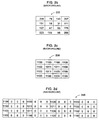
FIG. 3 illustrates the gray tile of FIG. 2c and
its decomposition into a base pixel value and a
fractional tile.
FIG. 4 illustrates a compressed representation of
eight bits of four fractional tiles in a 32-bit word.
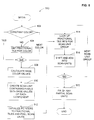
FIG. 5 and FIG. 6 together are a flow diagram of a
method of constructing scan units from fractional tiles.
FIG. 7 is a diagram illustrating apparatus
embodying the present invention.
Detailed Description
Referring to FIG. 1, a conventional rendering and
marking process for non-contone raster output devices is
enhanced by the addition of a method using fractional
tiles to produce gray tiles and color tiles (100). In a
printer, for example, a marking routine 104 is called to
print a sample gray or color level at a location (102).
The marking routine requests a gray or color tile from a
tile rendering process 110. Conventionally, the
rendering process will produce the requested tile 106
either by retrieving it from a cache of tiles or, if the
tile for the sample value is not in the cache, by
building the tile from a threshold array 112. Using
fractional tiles, the rendering process 110 builds the
requested tile from fractional tiles, as will be
described. Fractional tiles can be built by the tile
rendering process 110 using the same basic functions the
process previously used to build full tiles. Like full
tiles, fractional tiles 122 are advantageously stored in
a cache 120, because they are expensive to build. When
it has the tile 106 it requested, the marking routine 104
copies the pixels from the tile into appropriate part of
a frame buffer 116. It is conventional to organize a
frame buffer into scan lines divided into scan units and
for a marking routine to write full scan units 114 when
possible. The embodiment described in this specification
uses a scan unit of 32 bits.
Referring to FIG. 2a, the lesser (or base) pixel
value and the thresholding value for a sample value
(either a gray or a component of a color) can be computed
using the following formulas (in the style of the
language C):
Referring to FIG. 2d, a 4 x 4 component color tile
240 (a gray tile for a particular color component) has a
non-zero value in the position of only one of the color
components. The illustrated tile 240 is for the cyan
component of a chunky CMYK device. To make a composite
color tile, four gray tiles (one for each of the color
components) are merged to produce the color tile.
Merging is done simply by adding the pixel values from
each of the corresponding gray tiles.
Referring to FIG. 3, with fractional tiles, the
information contained in a gray tile is decomposed into a
base pixel value and a one-bit per pixel fractional tile.
Each one-bit pixel of the fractional tile chooses between
the base pixel value and the next pixel value. FIG. 3
shows the decomposition of gray tile 230 (FIG. 2c) into a
base pixel value 304 and a one-bit fractional tile 306.
There are exactly 17 of these one-bit fractional tiles
for the above example because GrayMax is exactly 17 times
(NGray-1).
It is advantageous to store a fractional tile in a
packed representation. In the process of producing a
gray tile, an eight-bit byte of the packed representation
is expanded to provide one bit per pixel. For a chunky
color tile, the one-bit pixel of each color-component
fractional tile is added to the corresponding color
component in the chunky color tile. Using the method
described below, eight pixels can be produced in each
iteration, so using fractional tiles to produce gray
tiles, and especially to produce chunky color tiles, can
be much faster than producing them from a threshold
array.
Referring to FIG. 5, a method 500 of building a
chunky color tile by halftoning a sample color having
four color components will be described. (In a
simplified form, the method can be used to build a gray
tile for a planar color or a multibit monochrome device.)
For each color component (506), unless the component is a
constant (creamy) color (502), the method gets a
fractional tile (504 and FIG. 6).
Referring to FIG. 6, the process 504 of getting a
fractional tile begins by getting the requested tile from
a cache of fractional tiles 120 (FIG. 1) if it is present
there (602). If it is not present, the fractional tile
is built (604) from the threshold array (which is
specific to the color component if separate screens are
used for each color component). The fractional tile is
stored in a parked representation. With a length of 32
bits, a word is packed with 32 one-bit pixe elements.
After it is built, the fractional tile is stored in the
fractional tile cache 120 (FIG. 1) (606).
Returning to FIG. 5, the base color value for each
color component is calculated (508) and a scan unit of
device pixels is created that contains the base color
value (the lesser value) of each component in each pixel
(510). For a chunky color device with four bits for each
of four color components, a 32-bit scan unit (word) will
contain two pixels of 16 bits each.
Next, pointers are initialized (512) for the
process of unpacking the fractional tiles and adding
their contents to the base values to create a chunky
color tile (514-522). For a group of four 32-bit scan
units (520) covering a total of eight 4-component pixels,
four 8-bit bytes (one for from each fractional tile for
component) are spread into one 32-bit word in a way that
facilitates masking and adding them into the four scan
units. One arrangement of bits (big-endian) for the
32-bit word is shown in table 402 of FIG. 4, which is the
one used in the process that will now be described. This
arrangement can be achieved by using each byte of a
fractional tile as an index into a lockup table, which
provides a 32-bit word with the fractional tile bits
spread as required (514). With the arrangement 402, and
a value of 0x11111111 (hexadecimal) as a mask, all the
fractional tile bits for four scan units (eight chunky
pixels) can be added to a scan unit containing base
values (built in step 510) in four mask-and-add
operations, each separated by a one-bit sift (516). In
the first operation, for example, bits 0-7 (FIG. 4) are
masked and added to eight 4-bit nibbles representing C,
M, Y, and K components of two pixels in one scan unit.
Then the word is shifted right one bit, bits 8-15 are
masked and added, and so on. Note that the add operation
cannot overflow across components because the largest
component value appears in the base pixel only if it is a
creamy color. Because a tile need not contain a whole
number of scan units, a partial scan unit may have to be
completed (522) before the chunky color tile is done.
With 256 possible input sample values and 16
device values, fractional tiles for different base values
can be the same, and it is therefore possible to reuse
fractional tiles with different base values (as long as
the threshold array remains unchanged). This is not true
in all cases. In general, the number of sample gray
levels that has to be halftoned is the total number
possible of sample gray levels minus the number output
values the device can produce. If this difference is
evenly divisible by the number of output values minus
one, the quottent is the number of different fractional
tiles that will be required.
Producing chunky color tiles from fractional tiles
has two significant advantages over the method of merging
component color tiles described earlier. First, using
fractional tiles requires less memory access since much
of the data is read from the smaller fractional tiles.
More significantly, the gray tiles need not be produced,
saving both the storage and the time required to
construct them.
The following table shows the possible reductions
in tile storage, data transfer, and halftoning that can
be realized from the use of fractional tiles. The
columns "Dithered grays" show the number of gray tiles
that must be cached to achieve all non-creamy gray levels
from cached tiles. The columns "Bits/pixel" is the
number of bits per pixel used in the cached form of the
gray tile. "Tile storage reduction" measures savings in
memory usage when caching all gray tiles that are needed
to print 256 sample gray levels. This is the memory
needed for the conventional gray tiles described above
divided by the memory needed for fractional tiles. In
the best case shown, the fractional tile method uses
1/960th of the memory used by the conventional method.
"Data transfer reduction" measures savings in memory
access when building a chunky color tile. It is bytes
read from memory and written to memory in the
conventional method desccibed above divided by the same
quantity in the fractional tile method. In the best case
shown, the fractional tile method requires 1/4th as much
memory access as the conventional method. (There is no
data transfer reduction for planar devices, but rather a
loss, as in the conventional method the tiles are stored
in their final format, while in the fractional tile
method the tiles must be expanded before they can be
used.) "Halftoning reduction" measures savings in
tile-building time when building all gray tiles that are
needed to print 256 sample gray levels. It is the number
of comparisons between the sample value and the threshold
array value in the innermost loop of the gray tile
building code of the conventional method divided by the
same for the fractional tile method. In the best case
shown, the fractional tile method does 1/60th as many
comparisons.
| Device Bits/plane | Conventional | | New | | Tile storage reduction | Data transfer reduction | Halftoning reduction |
| | Dithered grays | Bits/pixel | Dithered grays | Bits/pixels |
| Planar |
| |
| 1 | 254 | 1 | 254 | 1 | 1 | n/a | 1 |
| 2 | 252 | 2 | 84 | 1 | 6 | n/a | 3 |
| 4 | 240 | 4 | 16 | 1 | 60 | n/a | 15 |
| Chunky with separate screens for C, M, Y, and K |
| 1 | 1016 | 4 | 1016 | 1 | 4 | 2.50 | 1 |
| 2 | 1008 | 8 | 336 | 1 | 24 | 3.33 | 3 |
| 4 | 960 | 16 | 64 | 1 | 240 | 4.00 | 15 |
| Chunky with one common screen for C, M, Y, and K |
| 1 | 1016 | 4 | 254 | 1 | 16 | 2.50 | 4 |
| 2 | 1008 | 8 | 84 | 1 | 96 | 3.33 | 12 |
| 4 | 960 | 16 | 16 | 1 | 960 | 1.00 | 60 |
Referring to FIG. 7, the invention may be
implemented in digital electronic circuitry or in
computer hardware, firmware, software, or in combinations
of them. Apparatus of the invention may be implemented
in a computer program product tangibly embodied in a
machine-readable storage device for execution by a
computer processor; and method steps of the invention may
be performed by a computer processor executing a program
to perform functions of the invention by operating on
input data and generating output. Suitable processors
include, by way of example, both general and special
purpose microprocessors. Generally, a processor will
receive instructions and data from a read-only memory
and/or a random access memory. Storage devices suitable
for tangibly embodying computer program instructions
include all forms of non-volatile memory, including by
way of example semiconductor memory devices, such as
EPROM, EEPROM, and flash memory devices; magnetic disks
such as internal hard disks and removable disks;
magneto-optical disks; and CD-ROM disks. Any of the
foregoing may be supplemented by, or incorporated in,
specially-designed ASICs (application-specific integrated
circuits).
By way of example, a printing device 700
implementing an interpreter for a page description
language, such as the PostScript® language, includes a
microprocessor 702 for executing program instructions
(including font instructions) stored on a printer random
access memory (RAM) 704 and a printer read-only memory
(ROM) 706 and controlling a print marking engine 708.
The essential elements of a computer are a processor for
executing instructions and a memory. A computer can
generally also receive programs and data from a storage
medium such as a removable disk 712. These elements will
be found in a conventional desktop or workstation
computer 710 as well as other computers suitable for
executing computer programs implemetting the methods
described here, which may be used in conjunction with any
digital print engine or marking engine, display monitor,
or other raster output device capable of producing color
or gray scale pixels on paper, film, display screen, or
other output medium.
Other embodiments are within the scope of the
following claims. For example, the steps of the
invention may be changed by those skilled in the art and
still achieve desirable results. A fractional tile may
have a bit depth greater than one. The threshold arrays
need not be square, rectangular or of any other
particular shape. Threshold arrays are generally much
larger than the 4x4 arrays shown for illustrative
purposes in the figures. Commercially useful sizes
include 256x256 and 386x386. The number of sample levels
can have a value other than 256, both larger or smaller:
for example, the use of 4096 or even 65535 levels can be
advantageous in rendering fine gradients. The number of
levels in a color component can have a value other than
16, both larger or smaller: for example, values of 2, 4,
5, 3, 32, 64, 128, 256, and 4096 may each be advantageous
for particular applications.