EP0827653B1 - Method and apparatus for power control in a communication system - Google Patents
Method and apparatus for power control in a communication system Download PDFInfo
- Publication number
- EP0827653B1 EP0827653B1 EP97901358A EP97901358A EP0827653B1 EP 0827653 B1 EP0827653 B1 EP 0827653B1 EP 97901358 A EP97901358 A EP 97901358A EP 97901358 A EP97901358 A EP 97901358A EP 0827653 B1 EP0827653 B1 EP 0827653B1
- Authority
- EP
- European Patent Office
- Prior art keywords
- power
- control
- control group
- adjustment command
- control bit
- Prior art date
- Legal status (The legal status is an assumption and is not a legal conclusion. Google has not performed a legal analysis and makes no representation as to the accuracy of the status listed.)
- Expired - Lifetime
Links
Images


Classifications
-
- H—ELECTRICITY
- H04—ELECTRIC COMMUNICATION TECHNIQUE
- H04W—WIRELESS COMMUNICATION NETWORKS
- H04W52/00—Power management, e.g. TPC [Transmission Power Control], power saving or power classes
- H04W52/04—TPC
- H04W52/54—Signalisation aspects of the TPC commands, e.g. frame structure
- H04W52/58—Format of the TPC bits
Definitions
- the present invention relates generally to communication systems and, in particular, to power control in a communication system.
- Communication systems are known to employ power controi methods which control transmission energy of remote units.
- One such communication system employing power control is a spread spectrum communication system.
- Power control in a spread spectrum system serves two main functions. Firstly, because each remote unit's signal in a spread spectrum system is typically transmitted in the same frequency, a majority of the noise (which is inversely proportional to bit energy per noise density i.e., E b /N 0 , which is defined as the ratio of energy per information-bit to noise-spectral density), associated with a received signal can be attributed to other remote units' transmissions. The magnitude of noise is directly related to the received signal power of each of the other remote units' transmissions. Thus it is beneficial for a remote unit to transmit at the lowest power level possible.
- TIA/EIA/IS-95A Cellular System Remote unit-Base Station Compatibility Standard of the Electronic Industry Association/Telecommunications Industry Association interim standard 95
- TIA/EIA/IS-95A can be contacted at 2001 Pennsylvania Ave. NW Washington DC 20006.
- TIA/EIA/IS-95A Section 7.1.3.1.7
- a power-control subchannel is continuously transmitted on a forward traffic channel.
- the base station receives a power-control group transmitted from the remote unit.
- time slot "k+1" the base station calculates a power adjustment command to send to the remote unit.
- the base station transmits the power adjustment command to the remote unit. Finally, at timeslot "k+3", the base station receives the remote unit's transmitted signal at the corrected power level. This process of having a remote unit's power adjustment delayed until the third time slot after the base station receives a power-control group can negatively impact reverse channel performance.
- Reverse channel power control in a CDMA system is accomplished by adjusting the measurement time of a power-control transmission (power-control group) transmitted by a remote unit in order to calculate and transmit a power adjustment command (power-control bit) to the remote unit in the next power-control group transmitted by the base station. Transmitting a power adjustment command (power-control bit) in the next power-control group transmitted to the remote unit allows the base station to receive power-control adjustments in the second timeslot (k+2) after measurement of the power-control group which improves reverse channel performance by as much as 1 dB E b /N 0 .
- the present invention encompasses measuring a power-control transmission and discontinuing the measurement of the power-control transmission prior to completion based on a transmission time of a power adjustment command.
- An alternate embodiment encompasses a method of power control in a code-division, multiple-access (CDMA) communication system comprising the steps of beginning measurement of a power-control group and determining a transmission time of the next power-control bit. The measurement of the power-control group is then discontinued based on the transmission time. Finally a calculated power-control bit is transmitted to a remote unit.
- CDMA code-division, multiple-access
- Yet another alternate embodiment encompasses an apparatus for controlling power in a communication system.
- the apparatus comprises an integrator for measuring a power-control transmission and a logic unit for discontinuing the measurement of the power-control transmission based on a transmission time of a power adjustment command.
- Another embodiment encompasses a method for power control in a communication system.
- the method comprises the steps of determining a transmission time of a power adjustment command and estimating the power-adjustment command based on a previous power-adjustment command if the transmission time of the power adjustment command is below a threshold. If the transmission time of the power adjustment command is above the threshold, the power-adjustment command is estimated based on a shortened measurement of a power-control group.
- Yet another embodiment encompasses a method of power control in a communication system.
- the method comprises the steps of determining a transmission rate of a remote unit and switching between a two time slot delay and a three time slot delay when applying a power control command, where the switching is based on the transmission rate.
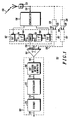
- FIG. 1 is a block diagram of a preferred embodiment of a base station receiver 100 for receiving a power-control group transmitted by a remote unit.
- Orthogonally encoded spread-spectrum digital signal 130 is received at receive antenna 131 and amplified by receiver 132 before being despread and demodulated 136 into in-phase 140 and quadrature 138 components.
- Components 138, 140 of despread digital samples are then grouped into predetermined length groups (e.g., 64 sample length groups) of sampled signals that are independently input to orthogonal decoders in the form of fast Hadamard transformers 142, 144, which despread the orthogonally encoded signal components producing a plurality of despread signal components 146 and 160, respectively (e.g.
- each transformer output signal 146, 160 has an associated Walsh index symbol which identifies each particular orthogonal code from within a set of mutually orthogonal codes (e.g. when 64 sample length groups are input, then a 6 bit length index data symbol can be associated with the transformer output signal to indicate the particular 64 bit length orthogonal code to which the transformer output signal corresponds).
- the energy values with the same Walsh index in each group of resulting signal 156 from each branch of receiver 100 will then be summed at summer 164 to provide a group of summed energy values 166.
- the energy value with index i in the group of summed energy values 166 corresponds to a measure of confidence that the group of sampled signals, which generate this group of summed energy values 166, corresponds to the i-th Walsh symbol.
- the group of summed energy values with associated indices will then be sent to a soft decision metric generator (such as a dual maxima metric generator) 168 where a single metric for each encoded data bit is determined, thereby producing a single set of aggregate soft decision data 170.
- the aggregate soft decision data 170 is then deinterleaved by deinterleaver 172 prior to final maximum likelihood decoding by decoder 176.
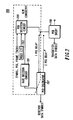
- FIG. 2 is a block diagram of a preferred embodiment of a CDMA transmitter 200 for transmitting a power-adjustment command to a remote unit.
- the power-adjustment command is a power-control bit such that a "0" bit indicates to the remote unit to increase the mean output power level, and a "1" bit indicates to the remote unit to decrease the mean output power level.
- Transmitter 200 is preferably a transmitter such as that defined by TIA/EIA/IS-95A.
- Transmitter 200 includes convolutional encoder 212, interleaver 216, orthogonal encoder 220, modulator 224, upconverter 228, and antenna 229.
- signal 210 (traffic channel data bits) is received by convolutional encoder 212 at a particular bit rate (e.g., 9.6 kbit/second).
- Input traffic channel data 210 bits typically include voice converted to data by a vocoder, pure data, or a combination of the two types of data.
- Convolutional encoder 212 encodes input data bits 210 into data symbols at a fixed encoding rate with an encoding algorithm which facilitates subsequent maximum likelihood decoding of the data symbols into data bits (e.g. convolutional or block coding algorithms).
- convolutional encoder 212 encodes input data bits 210 (received at a rate of 9.6 kbit/second) at a fixed encoding rate of one data bit to two data symbols (i.e., rate 2/2) such that convolutional encoder 212 outputs data symbols 214 at a 19.2 ksymbol/second rate.
- Data symbols 214 are then input into interleaver 216.
- Interleaver 216 interleaves the input data symbols 214 at the symbol level.
- data symbols 214 are individually input into a matrix which defines a predetermined size block of data symbols 214.
- Data symbols 214 are input into locations within the matrix so that the matrix is filled in a column by column manner.
- Data symbols 214 are individually output from locations within the matrix so that the matrix is emptied in a row by row manner.
- the matrix is a square matrix having a number of rows equal to the number of columns; however, other matrix forms can be chosen to increase the output interleaving distance between the consecutively input non-interleaved data symbols.
- Interleaved data symbols 218 are output by interleaver 216 at the same data symbol rate that they were input (e.g., 19.2 ksymbol/second).
- the predetermined size of the block of data symbols defined by the matrix is derived from the maximum number of data symbols which can be transmitted at a predetermined symbol rate within a predetermined length transmission block. For example, if the predetermined length of the transmission block is 20 milliseconds, then the predetermined size of the block of data symbols is 19.2 ksymbol/second times 20 milliseconds which equals 384 data symbols which defines a 16 by 24 matrix.
- Interleaved data symbols 218 are input to orthogonal encoder 220.
- Orthogonal encoder 220 modulo 2 adds an orthogonal code (e.g., a 64-ary Walsh code) to each interleaved and scrambled data symbol 218.
- an orthogonal code e.g., a 64-ary Walsh code
- interleaved and scrambled data symbols 218 are each replaced by a 64 symbol orthogonal code or its inverse.
- These 64 orthogonal codes preferably correspond to Walsh codes from a 64 by 64 Hadamard matrix wherein a Walsh code is a single row or column of the matrix.
- Orthogonal encoder 220 repetitively outputs a Walsh code or its inverse 222 which corresponds to input data symbol 218 at a fixed symbol rate (e.g., 19.2 ksymbol/second).
- the sequence of Walsh codes 222 is prepared for transmission over a communication channel by modulator 224.
- the spreading code is a user specific sequence of symbols or unique user code which is output at a fixed chip rate (e.g., 1.228 Mchip/second).
- the user code spread encoded chips are scrambled by a pair of short pseudorandom codes (i.e. short when compared to the long code) to generate an I-channel and Q-channel code spread sequence.
- the I-channel and Q-channel code spread sequences are used to bi-phase modulate a quadrature pair of sinusoids by driving the power level controls of the pair of sinusoids.
- the sinusoids output signals are summed, bandpass filtered, translated to an RF frequency, amplified, filtered via upconverter 228 and radiated by an antenna 229 to complete transmission of the channel data bits 210.
- FIG. 3 illustrates an apparatus 300 for receiving a power-control group (via a receiver described in FIG. 1) and transmitting a power adjustment command (via transmitter described in FIG. 2) in accordance with a preferred embodiment of the present invention.
- Apparatus 300 includes combined energy random access memory (combined energy RAM) 301, integrator 305, switch 303, energy adjust unit 307, power-control state machine 309, state switch 310, long code generator 311, long code advancer 314, and logic unit 315. Operation of apparatus 300 in accordance with a preferred embodiment of the present invention occurs as follows.
- Long code generator 311 outputs a long code to the long code advancer 314.
- Long code advancer 314 advances the long code by at least the power-control bit calculation time ( T calc ) added to the round trip delay time ( T rtd ) (i.e. T calc + T rtd ). This is done in order to determine the value of the long code for calculating the power-control bit location within the next power-control group.
- Logic unit 315 receives the advanced long code 316 from long code advancer 314 and determines from the advanced long code 316 at which of the 16 possible starting positions the power-control bit is transmitted. In a preferred embodiment (incorporating the TIA/EIA/IS-95A.
- T rtd between the base station and the remote unit needs to be taken into consideration.
- T measure ⁇ 1.25ms - T adv .
- logic unit 315 Once logic unit 315 has calculated the time necessary to measure the power-control group, it transmits this time to switch 303, which closes at the appropriate time passing the information regarding energy of the acquired modulation symbols to integrator 305. Integrator 305 sums the acquired modulation symbols and outputs a summed value to energy adjust unit 307. Energy adjust unit 307 estimates the value of the summed modulation symbols had all N modulation symbols in the power-control group been acquired. In the preferred embodiment, this is done simply by multiplying the summed value by .00125 T measure where .00125 is the total time of a power-control group transmission.
- the adjusted value of the summed modulation symbols is output to the power-control state machine 309.
- Power-control state machine 309 uses the adjusted value of the summed modulation symbols to determine the value ("0" or "1") of a power-control bit, and outputs this value to state switch 310.
- State switch 310 determines from the long code (generated by long code generator 311) which of the 16 possible starting positions the power-control bit is to be transmitted in and transmits the power-control bit accordingly.
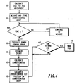
- FIG. 4 is a flow chart of a method of controlling reverse channel power in a CDMA system in accordance with a preferred embodiment of the present invention.
- the logic flow begins at step 401 where a time needed to measure the power-control group is determined.
- step 403 the measurement is started at the beginning of the power-control group.
- step 405 it is determined if T measure will be exceeded for continued measurement of the power-control group, and if not, at step 407 the measurement of the power-control group continues.
- the logic flow continues to step 409 where the measured power-control group is integrated.
- step 411 an estimate is made of the power-control group for the condition if all N modulation symbols in the power-control group had been acquired. In a preferred embodiment, this is done simply by multiplying the summed value by .00125 T measure
- step 413 the power-control bit is determined and at step 415 the power-control bit's position within the power-control group is determined.
- step 417 it is determined if it is time to send the power-control bit, and if so, at step 419, the power-control bit is sent to the remote unit, otherwise the logic flow simply returns to step 417.
- the remote unit change power at the beginning of a spread symbol, thus a new field of certain control messages is defined to allow the remote unit to shift from a three power-control group delay, to a two power-control group delay, and vise versa.
- the remote unit will alert the base station that it is two power-control group delay capable when setting up a call, and the base station switches from a three to a two power-control group delay once enough statistics have been taken to assure that T rtd is not greater than a predetermined amount.
- an instant delay decision may be made on a random access message and the command may be relayed in the channel assignment message. After a call has been up for some time, T rtd may become too large, and the base station may direct the remote unit to switch back to the three power-control group delay mode.
- FIG. 5 illustrates a time-domain diagram of controlling reverse channel power in a CDMA system in accordance with a preferred embodiment of the present invention.
- the power-control group is measured in timeslot "k" over at most a (1.25 - T adv ) ms period.
- the base station estimates the value of the received power, determines the value of the power-control bit ("0" or "1''), and transmits the power-control bit to the remote unit.
- the base station receives the remote unit's transmitted signal at the correct power level.
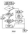
- FIG. 6 is a flow chart of a method of controlling reverse channel power in a CDMA system in accordance with an alternate embodiment of the present invention.
- this embodiment employs an algorithm to estimate the value of the power-control bit whenever the power-control bit slot appears too soon for the 1.25 ms energy measurement to be made with the power-control bit being transmitted in the next timeslot. Assuming the power-control and T rtd occurs within 50 ms, the algorithm would need to be invoked for only 1 of 16 power-control group measurements on average.
- the logic flow begins at step 601 where a time needed to measure the power-control group and still be able to transmit the power-control bit in the next timeslot is measured.
- step 603 it is determined if the time available to measure the power-control group is too small (e.g., ⁇ 1.25 ms). If at step 603, it is determined that the time available to measure the power-control group is not less than 1.25 ms, then standard power control measurements and storage takes place (at step 607), and the standard calculation of the power-control bit takes place (at step 613). Finally the power-control bit is transmitted at step 621.
- step 603 it is determined that the time available to measure the power-control group is less than 1.25 ms, then at step 609 it is determined if the prior measurement of the power-control group was less than, or greater than a predetermined amount. If the prior measurement was less than, or greater than a predetermined amount then at step 611 the value of the prior power-control bit is used for the current power-control bit value, and is transmitted at step 621. If at step 609 it is determined that the prior measurement of the power-control group was not less than, or was not greater than the predetermined amount, then at step 615 it is determined if the second prior power-control bit (power-control bit prior to the last power-control bit) was the same value as the prior power-control bit. If so, the value of the prior power-control bit is used for the current power-control bit value, and is transmitted at step 621. Otherwise the opposite value of the prior power-control bit is used for the current power-control bit value and is transmitted at step 621.
- the second prior power-control bit power-
- an estimate of the power-control bit is accomplished by utilizing prior power-control bits (as discussed above), but only if T measure will be less than some minimum amount (400 ⁇ s for example). If, for example. T measure is below 400 ⁇ s, the power-control bit will be estimated by using prior power-control bit values, otherwise if T measure is greater than 400 ⁇ s, the power-control bit will be estimated by measuring the power-control group for a shortened period of time as discussed above.
- TIA/EIA/IS-95A standards require that the remote unit does not apply a power-control bit generated corresponding to the time when the remote unit did not transmit a power-control group. Since the remote unit expects to receive a power-control bit in the third time slot after a power-control group is sent, the TIA/EIA/IS-95A standard has the remote unit ignoring power-control bits received three timeslots after a time slot in which the remote unit did not transmit a power-control group.
- a preferred embodiment of the present invention has the power-control bit being received by the remote unit one time slots after sending a power-control group, current TIA/EIA/IS-95A standards will have the remote unit ignoring power-control bits that it should not have, and vice versa. A solution for this problem is discussed in reference to FIG. 7.
- FIG. 7 illustrates apparatus 700 for controlling reverse channel power during sub-rate transmission in accordance with a preferred embodiment of the present invention.
- the apparatus 700 comprises power-control bit calculator 707, rate decision circuit 701, rule list 703, power-control bit selection circuit 705, and power-control bit inserter 709.
- power-control bit calculator 707 has two outputs. The first output is the value of the power-control bit for the last power-control group transmitted by the remote unit (as discussed above in reference to FIG. 5) while the second output is the value of the power-control bit for a power-control group transmitted by the remote unit two power-control groups prior (per EIA/TIA/IS-95A specification).
- Rate decision circuit 701 determines the current rate of operation (e.g., full, 1/2, 1/4 or 1/8 rate). Rate information is output from the rate decision circuit 701 and input into power-control bit selection circuit 705. Power-control bit selection circuit 705 utilizes the rate information and rule list 703 to determine what power-control group to utilize (either one power-control group prior or two power-control groups prior) in determining the power-control bit to be inserted. Power-control bit selection circuit 705 then chooses the appropriate power-control bit (transmitted from power-control bit calculator 707) and outputs it to power-control bit inserter 709.
- rate information e.g., full, 1/2, 1/4 or 1/8 rate.
- Power-control bit selection circuit 705 utilizes the rate information and rule list 703 to determine what power-control group to utilize (either one power-control group prior or two power-control groups prior) in determining the power-control bit to be inserted. Power-control bit selection circuit 705 then chooses the appropriate power-control bit (transmitted from power-control bit calculator 70
- rate decision circuit 701 utilizes an energy and phase measurement based on the last four power-control groups transmitted by the remote unit. Thresholds are set to keep the falsely deciding full rate below an acceptable maximum. Amplitude (A) and phase measurements (0) of the previous four power-control groups are received and input to a decision mechanism.
- Rate Decision Circuit Determination (1) start (2) - set initial thresholds (3) - modify thresholds based on previous frame rate (4) - examine power-control groups 0-3 ⁇ A, ⁇ per power-control group ⁇ A, ⁇ between power-control groups (5) - make initial rate estimate (6) - adjust thresholds (7) - examine next group of 4 power-control groups - ⁇ A, ⁇ per power-control group ⁇ A, ⁇ between power-control groups include previous power-control group data (8) - modify rate estimate (9) - if end-of-frame, return to step (2); else return to step (7) (10) - end
- Rule list 703 for selecting the appropriate power-control bit (pcb) is shown below.
- the first column denotes the power-control group number (0 to 15) transmitted by the remote unit.
- the other three columns are for the various rates noted at the head of each.
- the contents of the list is the number of the power-control group (pcg) to use when calculating the appropriate power-control bit.
- a rate estimate update is made.
- the "rule” (marked “rule” in the table) listed for the half rate frame is to use the prior power-control bit if both the prior and alternate slots were active, otherwise, use an alternate power-control bit.
- the power-control bit is calculated as shown in Table 2.
- PCG# pcb selected from power-control group numbered: 0 15 if slot 15 active; else pcb from slot 14 1 0 if slot 0 active for 1/8th rate and slot 15 active; else 15 2 0 3 1 1/8 th or 1/4 th 1/2 full 4 2 rule 3 5 3 rule 4 6 4 rule 5 7 5 rule 6 8 6 rule 7 9 7 rule 8 (8 if slots 7&8 active) 10 8 rule 9 11 9 rule 10 12 10 rule 11 13 11 rule 12 14 12 rule 13 15 13 rule 14
Description
| Rate Decision Circuit Determination | |
| (1) - | start |
| (2) - | set initial thresholds |
| (3) - | modify thresholds based on previous frame rate |
| (4) - | examine power-control groups 0-3 {A, Ø} per power-control group {A, Ø} between power-control groups |
| (5) - | make initial rate estimate |
| (6) - | adjust thresholds |
| (7) - | examine next group of 4 power-control groups - {A, Ø} per power-control group {A, Ø} between power-control groups include previous power-control group data |
| (8) - | modify rate estimate |
| (9) - | if end-of-frame, return to step (2); else return to step (7) |
| (10) - | end |
| Power-Control bit Utilization | |||
| PCG# pcb selected from power-control group numbered: | |||
| 0 | 15 if | ||
| 1 | 0 if slot 0 active for 1/8th rate and | slot 15 active; else 15 | |
| 2 | 0 | ||
| 3 | 1 | ||
| 1/8th or 1/4th | 1/2 | full | |
| 4 | 2 | | 3 |
| 5 | 3 | | 4 |
| 6 | 4 | | 5 |
| 7 | 5 | | 6 |
| 8 | 6 | | 7 |
| 9 | 7 | rule | 8 |
| (8 if slots 7&8 active) | |||
| 10 | 8 | | 9 |
| 11 | 9 | | 10 |
| 12 | 10 | | 11 |
| 13 | 11 | | 12 |
| 14 | 12 | | 13 |
| 15 | 13 | | 14 |
Claims (10)
- A method for power control in a communication system, the method comprising the step of:being characterised by the further step of:measuring a power-control transmission; andproducing a discontinued measurement of the power-control transmission by discontinuing, prior to completion, the measuring of the power-control transmission based on a transmission time of a power adjustment command.
- The method of claim 1 wherein the communication system comprises a spread-spectrum communication system.
- The method of claim 1 wherein the step of measuring the power-control transmission comprises measuring a power-control group.
- The method of claim 1 further comprising the steps of:producing an estimated value of the power adjustment command; andtransmitting the power adjustment command to produce a transmitted power adjustment command.
- The method of claim 4 wherein the estimated value of the power adjustment command is based on the discontinued measurement of the power-control transmission.
- An apparatus for controlling power in a communication system comprising:being characterised by:an integrator (305) for measuring a power-oontrol transmission; anda logic unit (315) coupled to the integrator, said logic unit discontinuing, prior to completion, the measurement of the power-control transmission based on a transmission time of a power adjustment command.
- The apparatus of claim 6 wherein the communication system comprises a spread-spectrum communication system.
- The apparatus of claim 6 wherein the power-control transmission comprises a power-control group.
- The apparatus of claim 6 further comprising:a power-control state machine (309) coupled to the integrator, said power-control state machine estimating a value of the power adjustment command; anda transmitter coupled to the power-control state machine, said transmitter transmitting the power adjustment command.
- The apparatus of claim 9 wherein the estimated value of the power adjustment command is based on the discontinued measurement of the power-control transmission.
Applications Claiming Priority (3)
| Application Number | Priority Date | Filing Date | Title |
|---|---|---|---|
| US08/616,801 US5751763A (en) | 1996-03-15 | 1996-03-15 | Method and apparatus for power control in a communication system |
| US616801 | 1996-03-15 | ||
| PCT/US1997/000167 WO1997034387A1 (en) | 1996-03-15 | 1997-01-03 | Method and apparatus for power control in a communication system |
Publications (3)
| Publication Number | Publication Date |
|---|---|
| EP0827653A1 EP0827653A1 (en) | 1998-03-11 |
| EP0827653A4 EP0827653A4 (en) | 2001-09-19 |
| EP0827653B1 true EP0827653B1 (en) | 2004-06-09 |
Family
ID=24470997
Family Applications (1)
| Application Number | Title | Priority Date | Filing Date |
|---|---|---|---|
| EP97901358A Expired - Lifetime EP0827653B1 (en) | 1996-03-15 | 1997-01-03 | Method and apparatus for power control in a communication system |
Country Status (9)
| Country | Link |
|---|---|
| US (1) | US5751763A (en) |
| EP (1) | EP0827653B1 (en) |
| JP (1) | JP3957321B2 (en) |
| KR (1) | KR100295995B1 (en) |
| CN (2) | CN1221086C (en) |
| BR (1) | BR9702103A (en) |
| CA (1) | CA2220003C (en) |
| DE (1) | DE69729413T2 (en) |
| WO (1) | WO1997034387A1 (en) |
Families Citing this family (49)
| Publication number | Priority date | Publication date | Assignee | Title |
|---|---|---|---|---|
| ZA965340B (en) | 1995-06-30 | 1997-01-27 | Interdigital Tech Corp | Code division multiple access (cdma) communication system |
| JP3254390B2 (en) * | 1996-10-18 | 2002-02-04 | 三菱電機株式会社 | Transmission power control device |
| US6081536A (en) | 1997-06-20 | 2000-06-27 | Tantivy Communications, Inc. | Dynamic bandwidth allocation to transmit a wireless protocol across a code division multiple access (CDMA) radio link |
| US6542481B2 (en) | 1998-06-01 | 2003-04-01 | Tantivy Communications, Inc. | Dynamic bandwidth allocation for multiple access communication using session queues |
| US5946356A (en) * | 1997-07-16 | 1999-08-31 | Motorola, Inc. | Method and apparatus for data transmission within a broad-band communications system |
| JP2914444B2 (en) * | 1997-07-22 | 1999-06-28 | 日本電気株式会社 | CDMA transceiver |
| KR100369602B1 (en) * | 1997-11-03 | 2003-04-11 | 삼성전자 주식회사 | Power control bit inserting method of cdma mobile communication system |
| US7394791B2 (en) | 1997-12-17 | 2008-07-01 | Interdigital Technology Corporation | Multi-detection of heartbeat to reduce error probability |
| US9525923B2 (en) | 1997-12-17 | 2016-12-20 | Intel Corporation | Multi-detection of heartbeat to reduce error probability |
| KR100416987B1 (en) * | 1998-03-19 | 2004-08-04 | 삼성전자주식회사 | Apparatus and method for inserting additional information in a communication system, capable of minimizing channel deterioration |
| JP3286247B2 (en) * | 1998-05-08 | 2002-05-27 | 松下電器産業株式会社 | Wireless communication system |
| KR100334818B1 (en) * | 1998-07-07 | 2002-08-27 | 삼성전자 주식회사 | Power control signal transmission method of mobile communication terminal device |
| US6275478B1 (en) * | 1998-07-10 | 2001-08-14 | Qualcomm Incorporated | Methods and apparatuses for fast power control of signals transmitted on a multiple access channel |
| KR100306285B1 (en) * | 1998-07-28 | 2001-11-01 | 윤종용 | Apparatus and method for gating transmission in control hold state of cdma communication system |
| US6381230B1 (en) * | 1998-07-28 | 2002-04-30 | Qualcomm Incorporated | Method and system for providing personal base station communications |
| FR2782587B1 (en) * | 1998-08-20 | 2000-09-22 | France Telecom | CDMA DIGITAL COMMUNICATIONS METHODS WITH REFERENCE SYMBOL DISTRIBUTION |
| KR100339034B1 (en) * | 1998-08-25 | 2002-10-11 | 삼성전자 주식회사 | Reverse-loop closed-loop power control device and method in control-split state of code division multiple access communication system |
| US6163708A (en) * | 1998-12-31 | 2000-12-19 | Nokia Mobile Phones Limited | Closed-loop power control method |
| KR100433910B1 (en) * | 1999-02-13 | 2004-06-04 | 삼성전자주식회사 | apparatus and method for controlling power for inter-frequency handoff in cdma communication system |
| US6249683B1 (en) * | 1999-04-08 | 2001-06-19 | Qualcomm Incorporated | Forward link power control of multiple data streams transmitted to a mobile station using a common power control channel |
| EP1045529B1 (en) * | 1999-04-12 | 2006-11-29 | Alcatel | A method for improving performances of a mobile radiocommunication system using a power control algorithm |
| DE69914876T2 (en) * | 1999-04-12 | 2005-01-05 | Alcatel | A method for improving the characteristics of a mobile radio communication system using a power control algorithm |
| KR100492968B1 (en) * | 1999-05-29 | 2005-06-07 | 삼성전자주식회사 | Apparatus and method for transmitting a channel signal gated in the control only substate of cdma communications system |
| EP1079541B1 (en) * | 1999-08-23 | 2005-04-13 | Alcatel | Method for improving mobile radiocommunication system performances using a power control algorithm |
| US6529494B1 (en) * | 1999-09-21 | 2003-03-04 | Telefonaktiebolaget Lm Ericsson (Publ) | Downlink timeslot power control in a time division multiple access system |
| FI107671B (en) * | 1999-10-08 | 2001-09-14 | Nokia Mobile Phones Ltd | Procedure and arrangement for timing the change of diversity coefficients in a cellular radio system |
| KR20010037017A (en) * | 1999-10-13 | 2001-05-07 | 박종섭 | Reverse direction power control method of mobile communication system |
| WO2001037455A1 (en) * | 1999-11-17 | 2001-05-25 | Motorola Inc. | Fast power control to mobile stations simultaneously initiating a random access transmission |
| US6658262B1 (en) * | 1999-12-27 | 2003-12-02 | Telefonaktiebolget Lm Ericsson (Publ) | Method and system for power control order message management |
| DE60006930T2 (en) * | 2000-02-08 | 2004-10-28 | Alcatel | Method for setting a transmission quality setpoint for transmission power control in a mobile radio transmission system |
| US6542756B1 (en) * | 2000-02-29 | 2003-04-01 | Lucent Technologies Inc. | Method for detecting forward link power control bits in a communication system |
| JP2001244879A (en) * | 2000-03-02 | 2001-09-07 | Matsushita Electric Ind Co Ltd | Transmission power control unit and its method |
| US6876866B1 (en) | 2000-07-13 | 2005-04-05 | Qualcomm Incorporated | Multi-state power control mechanism for a wireless communication system |
| JP3479836B2 (en) * | 2000-09-18 | 2003-12-15 | 日本電気株式会社 | CDMA receiver |
| US7069034B1 (en) * | 2000-11-22 | 2006-06-27 | Ericsson Inc. | Systems and methods for reduced forward link power control delay |
| SE0004923D0 (en) * | 2000-12-29 | 2000-12-29 | Ericsson Telefon Ab L M | Method and system of transmission power control |
| US6975880B2 (en) * | 2001-04-02 | 2005-12-13 | Qualcomm, Incorporated | Forward link power control of multiple data streams transmitted to a mobile station using a common power control channel |
| DE10123611A1 (en) * | 2001-05-15 | 2002-11-21 | Siemens Ag | Method for operating a cellular radio communications system with assigned stations uses a base station switched between operating states with/without closed loop antenna diversity to send a downlink signal to a subscriber station. |
| JP3577021B2 (en) * | 2001-09-12 | 2004-10-13 | 埼玉日本電気株式会社 | Mobile station and method for determining electric field state in mobile station |
| US7096034B2 (en) * | 2001-10-01 | 2006-08-22 | Microsoft Corporation | System and method for reducing power consumption for wireless communications by mobile devices |
| KR100849333B1 (en) * | 2001-10-12 | 2008-07-29 | 삼성전자주식회사 | Apparatus and method of channel estimator |
| KR100469245B1 (en) * | 2001-12-07 | 2005-02-02 | 엘지전자 주식회사 | Method for controlling power in forward link |
| KR100878808B1 (en) * | 2002-02-18 | 2009-01-14 | 엘지전자 주식회사 | Method for decision power control rate |
| FI115742B (en) * | 2002-03-28 | 2005-06-30 | Valtion Teknillinen | Power control procedure and a telecommunication system |
| US7120400B2 (en) * | 2002-12-09 | 2006-10-10 | Intel Corporation | Method and apparatus to control power of transmitter |
| JP4482293B2 (en) | 2003-07-03 | 2010-06-16 | パナソニック株式会社 | Base station apparatus and transmission method |
| US20050134119A1 (en) * | 2003-12-18 | 2005-06-23 | Bliley Paul D. | Time slotting power switching |
| US9832769B2 (en) * | 2009-09-25 | 2017-11-28 | Northwestern University | Virtual full duplex network communications |
| US9671074B2 (en) | 2013-03-13 | 2017-06-06 | Willis Electric Co., Ltd. | Modular tree with trunk connectors |
Family Cites Families (8)
| Publication number | Priority date | Publication date | Assignee | Title |
|---|---|---|---|---|
| US4261054A (en) * | 1977-12-15 | 1981-04-07 | Harris Corporation | Real-time adaptive power control in satellite communications systems |
| US5267262A (en) * | 1989-11-07 | 1993-11-30 | Qualcomm Incorporated | Transmitter power control system |
| SE467332B (en) * | 1990-06-21 | 1992-06-29 | Ericsson Telefon Ab L M | PROCEDURE FOR POWER CONTROL IN A DIGITAL MOBILE PHONE SYSTEM |
| US5452437A (en) * | 1991-11-18 | 1995-09-19 | Motorola, Inc. | Methods of debugging multiprocessor system |
| JP2937681B2 (en) * | 1993-03-18 | 1999-08-23 | 沖電気工業株式会社 | Transmission power control method |
| US5452473A (en) * | 1994-02-28 | 1995-09-19 | Qualcomm Incorporated | Reverse link, transmit power correction and limitation in a radiotelephone system |
| GB2288097B (en) * | 1994-03-23 | 1998-09-23 | Roke Manor Research | ATM queuing and scheduling apparatus |
| JP3422869B2 (en) * | 1995-01-27 | 2003-06-30 | 新日本石油株式会社 | Refrigeration oil composition that can be used for HCFC refrigerant and HFC refrigerant |
-
1996
- 1996-03-15 US US08/616,801 patent/US5751763A/en not_active Expired - Lifetime
-
1997
- 1997-01-03 WO PCT/US1997/000167 patent/WO1997034387A1/en active IP Right Grant
- 1997-01-03 EP EP97901358A patent/EP0827653B1/en not_active Expired - Lifetime
- 1997-01-03 CA CA002220003A patent/CA2220003C/en not_active Expired - Fee Related
- 1997-01-03 DE DE69729413T patent/DE69729413T2/en not_active Expired - Lifetime
- 1997-01-03 CN CNB97190202XA patent/CN1221086C/en not_active Expired - Fee Related
- 1997-01-03 JP JP53257997A patent/JP3957321B2/en not_active Expired - Fee Related
- 1997-01-03 KR KR1019970708131A patent/KR100295995B1/en not_active IP Right Cessation
- 1997-01-03 CN CNB2003101027130A patent/CN100499431C/en not_active Expired - Fee Related
- 1997-01-03 BR BR9702103A patent/BR9702103A/en not_active Application Discontinuation
Also Published As
| Publication number | Publication date |
|---|---|
| BR9702103A (en) | 1999-07-20 |
| CA2220003C (en) | 2003-03-18 |
| JP3957321B2 (en) | 2007-08-15 |
| CN1182513A (en) | 1998-05-20 |
| WO1997034387A1 (en) | 1997-09-18 |
| EP0827653A1 (en) | 1998-03-11 |
| EP0827653A4 (en) | 2001-09-19 |
| DE69729413T2 (en) | 2005-06-16 |
| CN1221086C (en) | 2005-09-28 |
| JPH11505693A (en) | 1999-05-21 |
| US5751763A (en) | 1998-05-12 |
| CA2220003A1 (en) | 1997-09-18 |
| KR19990014787A (en) | 1999-02-25 |
| KR100295995B1 (en) | 2001-08-07 |
| DE69729413D1 (en) | 2004-07-15 |
| CN100499431C (en) | 2009-06-10 |
| CN1533075A (en) | 2004-09-29 |
Similar Documents
| Publication | Publication Date | Title |
|---|---|---|
| EP0827653B1 (en) | Method and apparatus for power control in a communication system | |
| US5778030A (en) | Method and apparatus for power control in a communication system | |
| EP0827675B1 (en) | Method and apparatus for power control in a spread-spectrum communication system | |
| US9282573B2 (en) | Random access control method and system | |
| US5771461A (en) | Method and apparatus for power control of a first channel based on a signal quality of a second channel | |
| US6766146B1 (en) | Channel communication device and method for mobile communication system using transmission antenna diversity | |
| EP1013006A1 (en) | Power control device and method for reverse link common channel in mobile communication system | |
| WO1997002668A1 (en) | Power control for cdma communication systems | |
| EP1069798A1 (en) | Universal mobile telephone system network with improved rate matching method | |
| WO1999012275A1 (en) | Adaptive power control of a pilot sub-channel | |
| US7145917B1 (en) | Frame matching method and apparatus for use in a communication system | |
| KR100390741B1 (en) | Device for controlling power in modulator | |
| KR20030077908A (en) | Method and apparatus for controlling the power of mobile phone in a wireless telecommunication system | |
| MXPA97000310A (en) | Control of closed cycle power, of linkinverse in a multiple access system of cod pordivision |
Legal Events
| Date | Code | Title | Description |
|---|---|---|---|
| PUAI | Public reference made under article 153(3) epc to a published international application that has entered the european phase |
Free format text: ORIGINAL CODE: 0009012 |
|
| AK | Designated contracting states |
Kind code of ref document: A1 Designated state(s): DE FR GB |
|
| 17P | Request for examination filed |
Effective date: 19980318 |
|
| A4 | Supplementary search report drawn up and despatched |
Effective date: 20010806 |
|
| AK | Designated contracting states |
Kind code of ref document: A4 Designated state(s): DE FR GB |
|
| RIC1 | Information provided on ipc code assigned before grant |
Free format text: 7H 04K 1/00 A, 7H 04J 13/00 B, 7H 04B 7/005 B |
|
| GRAP | Despatch of communication of intention to grant a patent |
Free format text: ORIGINAL CODE: EPIDOSNIGR1 |
|
| GRAS | Grant fee paid |
Free format text: ORIGINAL CODE: EPIDOSNIGR3 |
|
| GRAA | (expected) grant |
Free format text: ORIGINAL CODE: 0009210 |
|
| AK | Designated contracting states |
Kind code of ref document: B1 Designated state(s): DE FR GB |
|
| REG | Reference to a national code |
Ref country code: GB Ref legal event code: FG4D |
|
| REF | Corresponds to: |
Ref document number: 69729413 Country of ref document: DE Date of ref document: 20040715 Kind code of ref document: P |
|
| ET | Fr: translation filed | ||
| PLBE | No opposition filed within time limit |
Free format text: ORIGINAL CODE: 0009261 |
|
| STAA | Information on the status of an ep patent application or granted ep patent |
Free format text: STATUS: NO OPPOSITION FILED WITHIN TIME LIMIT |
|
| 26N | No opposition filed |
Effective date: 20050310 |
|
| REG | Reference to a national code |
Ref country code: GB Ref legal event code: 732E Free format text: REGISTERED BETWEEN 20110127 AND 20110202 |
|
| REG | Reference to a national code |
Ref country code: DE Ref legal event code: R081 Ref document number: 69729413 Country of ref document: DE Owner name: MOTOROLA MOBILITY, INC. ( N.D. GES. D. STAATES, US Free format text: FORMER OWNER: MOTOROLA, INC., SCHAUMBURG, ILL., US Effective date: 20110324 Ref country code: DE Ref legal event code: R081 Ref document number: 69729413 Country of ref document: DE Owner name: MOTOROLA MOBILITY, INC. ( N.D. GES. D. STAATES, US Free format text: FORMER OWNER: MOTOROLA, INC., SCHAUMBURG, US Effective date: 20110324 |
|
| REG | Reference to a national code |
Ref country code: FR Ref legal event code: TP Owner name: MOTOROLA MOBILITY, INC., US Effective date: 20110912 |
|
| REG | Reference to a national code |
Ref country code: FR Ref legal event code: PLFP Year of fee payment: 19 |
|
| PGFP | Annual fee paid to national office [announced via postgrant information from national office to epo] |
Ref country code: DE Payment date: 20150128 Year of fee payment: 19 |
|
| PGFP | Annual fee paid to national office [announced via postgrant information from national office to epo] |
Ref country code: GB Payment date: 20150127 Year of fee payment: 19 Ref country code: FR Payment date: 20150119 Year of fee payment: 19 |
|
| REG | Reference to a national code |
Ref country code: DE Ref legal event code: R119 Ref document number: 69729413 Country of ref document: DE |
|
| GBPC | Gb: european patent ceased through non-payment of renewal fee |
Effective date: 20160103 |
|
| REG | Reference to a national code |
Ref country code: FR Ref legal event code: ST Effective date: 20160930 |
|
| PG25 | Lapsed in a contracting state [announced via postgrant information from national office to epo] |
Ref country code: GB Free format text: LAPSE BECAUSE OF NON-PAYMENT OF DUE FEES Effective date: 20160103 Ref country code: DE Free format text: LAPSE BECAUSE OF NON-PAYMENT OF DUE FEES Effective date: 20160802 |
|
| PG25 | Lapsed in a contracting state [announced via postgrant information from national office to epo] |
Ref country code: FR Free format text: LAPSE BECAUSE OF NON-PAYMENT OF DUE FEES Effective date: 20160201 |
|
| P01 | Opt-out of the competence of the unified patent court (upc) registered |
Effective date: 20230520 |