EP0826463B1 - Werkzeug für mit Schraubgewinde versehene Befestigungsmittel - Google Patents
Werkzeug für mit Schraubgewinde versehene Befestigungsmittel Download PDFInfo
- Publication number
- EP0826463B1 EP0826463B1 EP19970306351 EP97306351A EP0826463B1 EP 0826463 B1 EP0826463 B1 EP 0826463B1 EP 19970306351 EP19970306351 EP 19970306351 EP 97306351 A EP97306351 A EP 97306351A EP 0826463 B1 EP0826463 B1 EP 0826463B1
- Authority
- EP
- European Patent Office
- Prior art keywords
- threaded member
- annular portion
- projections
- internally threaded
- tool
- Prior art date
- Legal status (The legal status is an assumption and is not a legal conclusion. Google has not performed a legal analysis and makes no representation as to the accuracy of the status listed.)
- Expired - Lifetime
Links
- 230000015572 biosynthetic process Effects 0.000 claims description 27
- 238000005755 formation reaction Methods 0.000 claims description 27
- 230000006835 compression Effects 0.000 description 1
- 238000007906 compression Methods 0.000 description 1
- 230000001939 inductive effect Effects 0.000 description 1
- 238000004519 manufacturing process Methods 0.000 description 1
- 239000000523 sample Substances 0.000 description 1
Images
Classifications
-
- B—PERFORMING OPERATIONS; TRANSPORTING
- B25—HAND TOOLS; PORTABLE POWER-DRIVEN TOOLS; MANIPULATORS
- B25B—TOOLS OR BENCH DEVICES NOT OTHERWISE PROVIDED FOR, FOR FASTENING, CONNECTING, DISENGAGING OR HOLDING
- B25B13/00—Spanners; Wrenches
- B25B13/48—Spanners; Wrenches for special purposes
- B25B13/50—Spanners; Wrenches for special purposes for operating on work of special profile, e.g. pipes
-
- B—PERFORMING OPERATIONS; TRANSPORTING
- B25—HAND TOOLS; PORTABLE POWER-DRIVEN TOOLS; MANIPULATORS
- B25B—TOOLS OR BENCH DEVICES NOT OTHERWISE PROVIDED FOR, FOR FASTENING, CONNECTING, DISENGAGING OR HOLDING
- B25B23/00—Details of, or accessories for, spanners, wrenches, screwdrivers
Definitions
- the present invention relates to a tool for tightening and releasing screw threaded fasteners.
- European Patent Application 0722049 discloses a screw threaded fastener having a locking arrangement in which spring loaded pins engage complimentary formations of internally and externally threaded members.
- the externally threaded member has an axial bore, the pins being mounted on a spring element and are engaged in apertures through the wall of the externally threaded member, from the internal diameter thereof.
- an ABS sensor ring is used to secure the hub assembly of the wheel of a motor vehicle, on a tubular axle.
- the ABS sensor ring has a screw threaded central bore and a series of angularly spaced teeth around its outer periphery.
- an inductive probe is located radially outwardly of the teeth but in close proximity thereto, so that as the ring rotates, movement of the teeth will generate a signal which is a function of the speed of rotation.
- the senor ring has to be tightened to a relatively high torque.
- a torque load spaced axially from the sensor ring there is a problem of the tool twisting and disengaging from the projections.
- EP-A-0176969 discloses a wrench according to the preamble of independent claim 1 having a spigot formation mounted coaxially, centrally of a socket formation.
- the spigot formation engages a recess in the head of a screw threaded member to centre the socket formation with respect to the head.
- a tool for a screw threaded fastener having a externally threaded member, said externally threaded member having an axial bore extending at least part-way along the threaded portion thereof and radial bores extending through the wall of the threaded portion, an internally threaded member, the internally threaded member having a series of projections extending axially from one radial face thereof, said projections being spaced angularly of one another and a locking pin engaging in one of the radial bores in the externally threaded member and being biased outwardly from the axial bore of the externally threaded member into engagement between a pair of consecutive projections on the internally threaded member, said tool comprising a socket member having an annular portion, the internal diameter of the annular portion defining an axially extending formation which cooperates with the axially extending projections on the internally threaded member and by which torque loads may be transmitted from the socket member to the internally threaded member, and a
- the internally threaded member may be tightened on the externally threaded member using the socket member, until the required torque is approached.
- the socket may then be removed and the locking pin inserted through the radial bore of the externally threaded member from within the axial bore, so that the locking pin is biased outwardly into engagement with the projections on the externally threaded member.
- the socket member may then be re-engaged with the projections on the internally threaded member, the bifurcation on the spigot formation serving to accommodate the locking pin and align the radially extending recess on the annular portion of the socket with the radial bore through which the locking pin is located.
- the internally threaded member may then be further tightened on the externally threaded member, until the locking pin engages between successive projections.
- Engagement of the spigot in the bore of the externally threaded member will stabilise the socket formation so that the tendency for the socket to twist out of engagement with the projections on the internally threaded member upon application of torque loads at a distance spaced axially from the internally threaded member, will be overcome.
- the axial extent of the projections may thus be minimised.
- the bifurcation on the spigot formation diverges outwardly in order to assist in alignment with the locking pin.
- the socket member may be associated in fixed or detachable relationship to means for applying torque loads, in conventional manner.
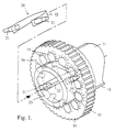
- an ABS sensor ring 10 is secured on a tubular axle 11, a screw thread on the internal diameter 12 of the sensor ring 10 engaging a corresponding screw thread 13 on the external diameter of the tubular axle 11.
- a series of diametrically opposed bores 14 extend radially through the wall of the tubular axle 11.
- a series of axially extending angularly spaced projections 15 are provided on the outer radial end face 16 of the sensor ring 10.
- a locking pin assembly 20 comprises a pair of locking pins 21 disposed one at each end of a U-shaped spring element 22.
- the locking pins 21 are engaged in a pair of the diametrically opposed bores 14 by compression of the spring element 22 and inserting the pins 21 into the bores 14 from within the bore 23 of the tubular axle 11, so that pins 21 are biased outwardly and engaged between adjacent projections 15 on the sensor ring 10.
- the sensor ring 10 is thereby prevented from rotating with respect to the tubular axle 11, by means of the locking pins 21.
- the sensor ring 10 is tightened against the inner race of a wheel bearing assembly (not shown) to locate a wheel hub on the axle 11.
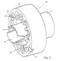
- a tool 25 for tightening and loosening the ABS sensor ring 10 comprises a socket member 26.
- the socket member 26 comprises a drive socket 27 by which means, for example a lever or pneumatic brace may be drivingly connected to the socket member 26, in conventional manner.
- an annular portion 28 defines axially extending formations 29 corresponding to the projections 15 on the sensor ring 10.
- the socket member 26 may thus be located on the end face 16 of sensor ring 10, so that the axially extending formations 29 on the socket member 26 engage the projections 15 on the sensor ring 10 so as to transmit torque loads from the socket member 26 to the sensor ring 10.
- Diametrically opposed recesses 30 are provided in the free end of the annular portion 28, to provide a clearance for the locking pins 21.
- a tubular spigot formation 31 extends coaxially of the annular portion 28 of socket member 26, for engagement in the axial bore 23 of tubular axle 11.
- the spigot formation 31 may be tapered towards its outer end, to facilitate location in the bore 23 of tubular axle 11.
- the free end of the spigot formation 31 is bifurcated, the bifurcation 33 diverging outwardly.
- the bifurcation 33 is aligned diametrically with the recesses 30 in the annular portion 28.
- the socket member 26 In order to tighten or loosen the ABS sensor ring 10 on the tubular axle 11 when the locking pin assembly 20 is removed, the socket member 26 is located over the end face 16 of the sensor ring 10, so that the spigot formation 31 engages in the bore of the tubular axle 11 and the formations 29 on the internal diameter of the annular portion 28 engage the projections 15 on the sensor ring 10. Torque loads may then be applied to the socket member 26 to tighten or loosen the sensor ring 10.
- the sensor ring 10 When assembling the sensor ring 10 on the axle 11, the sensor ring 10 is tightened to the required torque by means of a socket member 26.
- the socket member 26 is then removed from the end face 16 of the sensor ring 10 and the locking pin assembly 20 is inserted into the bore 23 of axle 11, so that the locking pins 21 engage through a pair of diametrically opposed radial bores 14 which are most closely aligned to gaps between adjacent projections 15 on the sensor ring 10.
- the socket member 26 is then re-engaged with the end face 16 of sensor ring 10, the locking pin assembly 20 within the bore 23 of axle 11 being located in the bifurcation 33 of spigot formation 31.
- the bifurcation 33 will then guide the socket member 26 onto the face 16 of sensor ring 10, so that the recesses 30 are aligned with the locking pins 21.
- the sensor ring 10 may then be further tightened until the locking pins 21 are aligned with gaps between adjacent projections 15 and under the influence of the spring element 22 will spring into the gaps to lock the sensor ring.
- the tool in accordance with the present invention may be used with any screw threaded fasteners in which a locking pin assembly is located in an axial bore of the externally threaded member.
Landscapes
- Engineering & Computer Science (AREA)
- Mechanical Engineering (AREA)
- Details Of Spanners, Wrenches, And Screw Drivers And Accessories (AREA)
- Snaps, Bayonet Connections, Set Pins, And Snap Rings (AREA)
Claims (4)
- Werkzeug für ein Befestigungselement mit Schraubengewinde mit einem Außengewindeteil, wobei besagtes Außengewindeteil (11) eine axiale Bohrung (23) aufweist, die sich wenigstens teilweise über den Gewindeabschnitt (13) desselben erstreckt, sowie radiale Bohrungen (14), die sich durch die Wand des Gewindeabschnittes (13) erstrecken, und ein Innengewindeteil (10), wobei das Innengewindeteil (10) eine Reihe von axial von einer Radialseite desselben abstehenden Vorsprüngen (15) aufweist, wobei besagte Vorsprünge (15) im Winkel von einander beabstandet sind, und einen Sperrstift (21), welcher in eine der Radialbohrungen (14) in dem Außengewindeteil (11) eingreift und von der Axialbohrung (23) des Außengewindeteils (11) nach außen vorgespannt ist, so daß er in Eingriff zwischen zwei nebeneinander liegende Vorsprünge (15) des Innengewindeteils (10) gedrückt wird, wobei besagtes Werkzeug (26) ein Glockenelement (27) mit einem ringförmigen Abschnitt (28) aufweist, wobei der Innendurchmesser des ringförmigen Abschnittes sich axial erstreckende Anformungen (29) aufweist, die mit den sich axial erstreckenden Vorsprüngen (15) am Innengewindeteil (10) zusammenwirken, und über welche Drehmoment von dem Glockenteil (27) auf das Innengewindeteil (10) übertragen werden kann, und eine zentrale, zu dem ringförmigen Abschnitt (28) koaxiale Klauenausbildung (31),
dadurch gekennzeichnet, daß eine sich radial erstreckende Ausnehmung (30) in einer Stirnfläche des ringförmigen Abschnittes (28) vorgesehen ist, welche den Sperrstift (21) des Befestigungselementes mit Schraubengewinde aufnimmt, wobei die Klauenausbildung (31) so ausgelegt ist, daß sie in die Bohrung (23) im Innengewindeteil (11) eingeführt werden kann, wobei das Ende der Klauenausbildung (31) gabelförmig ausgebildet ist, wobei die Gabelung (33) mit der sich radial erstreckenden Ausnehmung (30) in der Stirnfläche des ringförmigen Abschnittes (28) des Glockenteils (26) fluchtend ausgerichtet ist. - Werkzeug nach Anspruch 1, dadurch gekennzeichnet, daß die Gabelung (33) in der Klauenausbildung (31) nach außen auseinanderläuft.
- Werkzeug nach Anspruch 1 oder 2, dadurch gekennzeichnet, daß zwei Ausnehmungen (30) in dem ringförmigen Teil des Glockenteils vorgesehen sind, wobei die Ausnehmungen diametral mit der Gabelung (33) fluchten.
- Werkzeug nach einem beliebigen der vorangehenden Ansprüche, dadurch gekennzeichnet, daß ein Endabschnitt der Klauenausbildung von seinem freien Ende aus konisch nach außen verläuft.
Applications Claiming Priority (2)
| Application Number | Priority Date | Filing Date | Title |
|---|---|---|---|
| GBGB9617920.5A GB9617920D0 (en) | 1996-08-28 | 1996-08-28 | Tool for screw threaded fasteners |
| GB9617920 | 1996-08-28 |
Publications (2)
| Publication Number | Publication Date |
|---|---|
| EP0826463A1 EP0826463A1 (de) | 1998-03-04 |
| EP0826463B1 true EP0826463B1 (de) | 2000-07-12 |
Family
ID=10799020
Family Applications (1)
| Application Number | Title | Priority Date | Filing Date |
|---|---|---|---|
| EP19970306351 Expired - Lifetime EP0826463B1 (de) | 1996-08-28 | 1997-08-20 | Werkzeug für mit Schraubgewinde versehene Befestigungsmittel |
Country Status (3)
| Country | Link |
|---|---|
| EP (1) | EP0826463B1 (de) |
| DE (1) | DE69702483T2 (de) |
| GB (1) | GB9617920D0 (de) |
Family Cites Families (8)
| Publication number | Priority date | Publication date | Assignee | Title |
|---|---|---|---|---|
| DE468255C (de) * | 1927-06-22 | 1928-11-09 | Fritz Schott | Vereinigter Steck- und Schraubenschluessel |
| US1854116A (en) * | 1930-03-13 | 1932-04-12 | Schebeko Alex De | Tool |
| US3071995A (en) * | 1960-10-07 | 1963-01-08 | Jr William E Ruthrauff | Tool for fasteners |
| DE1603762A1 (de) * | 1967-04-11 | 1971-02-18 | Daimler Benz Ag | Schluessel zum Loesen von Verschraubungen |
| US4006660A (en) * | 1973-09-08 | 1977-02-08 | Yamamoto Byora Co., Ltd. | Fastener element |
| DE3436204A1 (de) * | 1984-10-03 | 1986-04-03 | Eberhard Jaeger GmbH & Co KG Verbindungstechnik, 5928 Bad Laasphe | Schraube und eindrehwerkzeug hierfuer |
| DE3807741A1 (de) * | 1988-03-09 | 1989-09-21 | Jaeger Eberhard Gmbh | Kopfschraube mit einer fuer einen innenantrieb vorgesehenen senkung |
| GB9500623D0 (en) * | 1995-01-12 | 1995-03-01 | Jaguar Cars | Screw threaded fastenings |
-
1996
- 1996-08-28 GB GBGB9617920.5A patent/GB9617920D0/en active Pending
-
1997
- 1997-08-20 EP EP19970306351 patent/EP0826463B1/de not_active Expired - Lifetime
- 1997-08-20 DE DE1997602483 patent/DE69702483T2/de not_active Expired - Fee Related
Also Published As
| Publication number | Publication date |
|---|---|
| EP0826463A1 (de) | 1998-03-04 |
| GB9617920D0 (en) | 1996-10-09 |
| DE69702483T2 (de) | 2000-11-09 |
| DE69702483D1 (de) | 2000-08-17 |
Similar Documents
| Publication | Publication Date | Title |
|---|---|---|
| US6190102B1 (en) | Studs for connecting a wheel and a brake element to a motor vehicle wheel hub unit | |
| EP1184581B1 (de) | Befestigungsmittel mit Gewinde | |
| US5318375A (en) | Lock for securing a coupling sleeve | |
| CA1251345A (en) | Self-locking, releasable lock nut | |
| US6095735A (en) | Locking nut assembly | |
| US5219254A (en) | Expandable fastener and locking means therefor | |
| US4708397A (en) | Motor vehicle wheel mounting means and method | |
| US5069587A (en) | Securing nut apparatus | |
| JPH0283105A (ja) | 締め付け具 | |
| CA2236547A1 (en) | Taperlock axle apparatus and flange | |
| JPH0660654B2 (ja) | 緩み止め締結具組立体 | |
| JPH0321847Y2 (de) | ||
| US4988231A (en) | Bushing | |
| WO1996012114A1 (en) | Fastening device | |
| US6935005B2 (en) | Installation of, a hub/bearing assembly for an automotive vehicle | |
| US6957918B2 (en) | Axle shaft assembly | |
| WO2002053940A2 (en) | Mounting system for speed reducers | |
| US5558457A (en) | Chucking device for fixing a hollow shaft to a shaft | |
| EP0253496B1 (de) | Sicherheitsradmutter oder -bolzen | |
| EP0826463B1 (de) | Werkzeug für mit Schraubgewinde versehene Befestigungsmittel | |
| US20060145531A1 (en) | Wheel fixing device particularly for go-karts or similar vehicles | |
| US20010028170A1 (en) | Tube nut and threaded connection between a brake hose and a brake line | |
| EP0722049B1 (de) | Gewindebefestigung | |
| US5056870A (en) | Wheel nut assembly | |
| US20030140664A1 (en) | Anti-theft fastener device |
Legal Events
| Date | Code | Title | Description |
|---|---|---|---|
| PUAI | Public reference made under article 153(3) epc to a published international application that has entered the european phase |
Free format text: ORIGINAL CODE: 0009012 |
|
| AK | Designated contracting states |
Kind code of ref document: A1 Designated state(s): DE FR GB |
|
| AX | Request for extension of the european patent |
Free format text: AL;LT;LV;RO;SI |
|
| 17P | Request for examination filed |
Effective date: 19980803 |
|
| AKX | Designation fees paid |
Free format text: DE FR GB |
|
| RBV | Designated contracting states (corrected) |
Designated state(s): DE FR GB |
|
| 17Q | First examination report despatched |
Effective date: 19990105 |
|
| GRAG | Despatch of communication of intention to grant |
Free format text: ORIGINAL CODE: EPIDOS AGRA |
|
| GRAG | Despatch of communication of intention to grant |
Free format text: ORIGINAL CODE: EPIDOS AGRA |
|
| GRAH | Despatch of communication of intention to grant a patent |
Free format text: ORIGINAL CODE: EPIDOS IGRA |
|
| GRAH | Despatch of communication of intention to grant a patent |
Free format text: ORIGINAL CODE: EPIDOS IGRA |
|
| GRAA | (expected) grant |
Free format text: ORIGINAL CODE: 0009210 |
|
| AK | Designated contracting states |
Kind code of ref document: B1 Designated state(s): DE FR GB |
|
| REF | Corresponds to: |
Ref document number: 69702483 Country of ref document: DE Date of ref document: 20000817 |
|
| ET | Fr: translation filed | ||
| PLBE | No opposition filed within time limit |
Free format text: ORIGINAL CODE: 0009261 |
|
| STAA | Information on the status of an ep patent application or granted ep patent |
Free format text: STATUS: NO OPPOSITION FILED WITHIN TIME LIMIT |
|
| 26N | No opposition filed | ||
| REG | Reference to a national code |
Ref country code: GB Ref legal event code: IF02 |
|
| PGFP | Annual fee paid to national office [announced via postgrant information from national office to epo] |
Ref country code: DE Payment date: 20080829 Year of fee payment: 12 |
|
| PGFP | Annual fee paid to national office [announced via postgrant information from national office to epo] |
Ref country code: FR Payment date: 20080807 Year of fee payment: 12 |
|
| PGFP | Annual fee paid to national office [announced via postgrant information from national office to epo] |
Ref country code: GB Payment date: 20080708 Year of fee payment: 12 |
|
| GBPC | Gb: european patent ceased through non-payment of renewal fee |
Effective date: 20090820 |
|
| REG | Reference to a national code |
Ref country code: FR Ref legal event code: ST Effective date: 20100430 |
|
| PG25 | Lapsed in a contracting state [announced via postgrant information from national office to epo] |
Ref country code: FR Free format text: LAPSE BECAUSE OF NON-PAYMENT OF DUE FEES Effective date: 20090831 Ref country code: DE Free format text: LAPSE BECAUSE OF NON-PAYMENT OF DUE FEES Effective date: 20100302 |
|
| PG25 | Lapsed in a contracting state [announced via postgrant information from national office to epo] |
Ref country code: GB Free format text: LAPSE BECAUSE OF NON-PAYMENT OF DUE FEES Effective date: 20090820 |