EP0826383B1 - Device for on-line cleaning and filling of an extra corporeal blood circuit of a dialysis apparatus - Google Patents
Device for on-line cleaning and filling of an extra corporeal blood circuit of a dialysis apparatus Download PDFInfo
- Publication number
- EP0826383B1 EP0826383B1 EP97118498A EP97118498A EP0826383B1 EP 0826383 B1 EP0826383 B1 EP 0826383B1 EP 97118498 A EP97118498 A EP 97118498A EP 97118498 A EP97118498 A EP 97118498A EP 0826383 B1 EP0826383 B1 EP 0826383B1
- Authority
- EP
- European Patent Office
- Prior art keywords
- blood
- line
- pump
- drip chamber
- venous
- Prior art date
- Legal status (The legal status is an assumption and is not a legal conclusion. Google has not performed a legal analysis and makes no representation as to the accuracy of the status listed.)
- Expired - Lifetime
Links
Images


Classifications
-
- A—HUMAN NECESSITIES
- A61—MEDICAL OR VETERINARY SCIENCE; HYGIENE
- A61M—DEVICES FOR INTRODUCING MEDIA INTO, OR ONTO, THE BODY; DEVICES FOR TRANSDUCING BODY MEDIA OR FOR TAKING MEDIA FROM THE BODY; DEVICES FOR PRODUCING OR ENDING SLEEP OR STUPOR
- A61M1/00—Suction or pumping devices for medical purposes; Devices for carrying-off, for treatment of, or for carrying-over, body-liquids; Drainage systems
- A61M1/36—Other treatment of blood in a by-pass of the natural circulatory system, e.g. temperature adaptation, irradiation ; Extra-corporeal blood circuits
- A61M1/3621—Extra-corporeal blood circuits
- A61M1/3643—Priming, rinsing before or after use
-
- A—HUMAN NECESSITIES
- A61—MEDICAL OR VETERINARY SCIENCE; HYGIENE
- A61M—DEVICES FOR INTRODUCING MEDIA INTO, OR ONTO, THE BODY; DEVICES FOR TRANSDUCING BODY MEDIA OR FOR TAKING MEDIA FROM THE BODY; DEVICES FOR PRODUCING OR ENDING SLEEP OR STUPOR
- A61M1/00—Suction or pumping devices for medical purposes; Devices for carrying-off, for treatment of, or for carrying-over, body-liquids; Drainage systems
- A61M1/14—Dialysis systems; Artificial kidneys; Blood oxygenators ; Reciprocating systems for treatment of body fluids, e.g. single needle systems for hemofiltration or pheresis
- A61M1/16—Dialysis systems; Artificial kidneys; Blood oxygenators ; Reciprocating systems for treatment of body fluids, e.g. single needle systems for hemofiltration or pheresis with membranes
- A61M1/1601—Control or regulation
-
- A—HUMAN NECESSITIES
- A61—MEDICAL OR VETERINARY SCIENCE; HYGIENE
- A61M—DEVICES FOR INTRODUCING MEDIA INTO, OR ONTO, THE BODY; DEVICES FOR TRANSDUCING BODY MEDIA OR FOR TAKING MEDIA FROM THE BODY; DEVICES FOR PRODUCING OR ENDING SLEEP OR STUPOR
- A61M1/00—Suction or pumping devices for medical purposes; Devices for carrying-off, for treatment of, or for carrying-over, body-liquids; Drainage systems
- A61M1/34—Filtering material out of the blood by passing it through a membrane, i.e. hemofiltration or diafiltration
- A61M1/342—Adding solutions to the blood, e.g. substitution solutions
- A61M1/3424—Substitution fluid path
- A61M1/3427—Substitution fluid path back through the membrane, e.g. by inverted trans-membrane pressure [TMP]
-
- A—HUMAN NECESSITIES
- A61—MEDICAL OR VETERINARY SCIENCE; HYGIENE
- A61M—DEVICES FOR INTRODUCING MEDIA INTO, OR ONTO, THE BODY; DEVICES FOR TRANSDUCING BODY MEDIA OR FOR TAKING MEDIA FROM THE BODY; DEVICES FOR PRODUCING OR ENDING SLEEP OR STUPOR
- A61M1/00—Suction or pumping devices for medical purposes; Devices for carrying-off, for treatment of, or for carrying-over, body-liquids; Drainage systems
- A61M1/34—Filtering material out of the blood by passing it through a membrane, i.e. hemofiltration or diafiltration
- A61M1/342—Adding solutions to the blood, e.g. substitution solutions
- A61M1/3455—Substitution fluids
- A61M1/3465—Substitution fluids using dialysate as substitution fluid
-
- A—HUMAN NECESSITIES
- A61—MEDICAL OR VETERINARY SCIENCE; HYGIENE
- A61M—DEVICES FOR INTRODUCING MEDIA INTO, OR ONTO, THE BODY; DEVICES FOR TRANSDUCING BODY MEDIA OR FOR TAKING MEDIA FROM THE BODY; DEVICES FOR PRODUCING OR ENDING SLEEP OR STUPOR
- A61M1/00—Suction or pumping devices for medical purposes; Devices for carrying-off, for treatment of, or for carrying-over, body-liquids; Drainage systems
- A61M1/36—Other treatment of blood in a by-pass of the natural circulatory system, e.g. temperature adaptation, irradiation ; Extra-corporeal blood circuits
- A61M1/3621—Extra-corporeal blood circuits
- A61M1/3643—Priming, rinsing before or after use
- A61M1/3644—Mode of operation
- A61M1/3647—Mode of operation with recirculation of the priming solution
-
- A—HUMAN NECESSITIES
- A61—MEDICAL OR VETERINARY SCIENCE; HYGIENE
- A61M—DEVICES FOR INTRODUCING MEDIA INTO, OR ONTO, THE BODY; DEVICES FOR TRANSDUCING BODY MEDIA OR FOR TAKING MEDIA FROM THE BODY; DEVICES FOR PRODUCING OR ENDING SLEEP OR STUPOR
- A61M1/00—Suction or pumping devices for medical purposes; Devices for carrying-off, for treatment of, or for carrying-over, body-liquids; Drainage systems
- A61M1/36—Other treatment of blood in a by-pass of the natural circulatory system, e.g. temperature adaptation, irradiation ; Extra-corporeal blood circuits
- A61M1/3621—Extra-corporeal blood circuits
- A61M1/3643—Priming, rinsing before or after use
- A61M1/3644—Mode of operation
- A61M1/365—Mode of operation through membranes, e.g. by inverted trans-membrane pressure [TMP]
-
- A—HUMAN NECESSITIES
- A61—MEDICAL OR VETERINARY SCIENCE; HYGIENE
- A61M—DEVICES FOR INTRODUCING MEDIA INTO, OR ONTO, THE BODY; DEVICES FOR TRANSDUCING BODY MEDIA OR FOR TAKING MEDIA FROM THE BODY; DEVICES FOR PRODUCING OR ENDING SLEEP OR STUPOR
- A61M1/00—Suction or pumping devices for medical purposes; Devices for carrying-off, for treatment of, or for carrying-over, body-liquids; Drainage systems
- A61M1/14—Dialysis systems; Artificial kidneys; Blood oxygenators ; Reciprocating systems for treatment of body fluids, e.g. single needle systems for hemofiltration or pheresis
- A61M1/16—Dialysis systems; Artificial kidneys; Blood oxygenators ; Reciprocating systems for treatment of body fluids, e.g. single needle systems for hemofiltration or pheresis with membranes
-
- Y—GENERAL TAGGING OF NEW TECHNOLOGICAL DEVELOPMENTS; GENERAL TAGGING OF CROSS-SECTIONAL TECHNOLOGIES SPANNING OVER SEVERAL SECTIONS OF THE IPC; TECHNICAL SUBJECTS COVERED BY FORMER USPC CROSS-REFERENCE ART COLLECTIONS [XRACs] AND DIGESTS
- Y10—TECHNICAL SUBJECTS COVERED BY FORMER USPC
- Y10S—TECHNICAL SUBJECTS COVERED BY FORMER USPC CROSS-REFERENCE ART COLLECTIONS [XRACs] AND DIGESTS
- Y10S210/00—Liquid purification or separation
- Y10S210/929—Hemoultrafiltrate volume measurement or control processes
Definitions
- the invention relates to an arrangement for rinsing and filling a extracorporeal blood circulation of dialysis machines, in particular of Blood tubing and dialyzers.
- the filling includes the vent of the extracorporeal blood circulation required for a dialysis treatment indispensable condition.
- US-A-4552721 discloses an arrangement for rinsing and filling a Extracorporeal blood circulation of dialysis machines, in which a bag with a Saline solution is connected to the arterial blood tubing.
- the arterial Blood tubing is connected to a blood pump and a drip chamber Provided.
- the arterial blood tubing and the venous blood tubing are connected to the dialyzer, and into the venous blood tubing is a switched on further drip chamber.
- From the upper ends of the two Drip chambers branch lines to a dialysis control unit to control the pressure to monitor in the two blood tubing lines. Subsequently, the Patient-side ends of the blood tubing are connected to a in the main lines existing disinfecting liquid on all line sections to be able to distribute.
- EP-A-0228106 discloses a device for filtering plasma from blood one arterial and one venous blood tubing to a plasma filter are connected and where this extracorporeal blood circulation as usual with Saline solution from a bag connected to a blood tubing is filled.
- the other blood tubing is connected to a blood pump, which promotes the saline solution through the blood tubing and the plasma filter, wherein in the plasma filter located air from the patient end of the Blood tube is discharged.
- the present invention is based on the object, an arrangement indicate flushing, de-aerating and filling an extracorporeal blood circulation of dialysis machines is simplified.
- the generated or processed by the dialysis machine Dialysis fluid for the purpose of purging, venting and filling by the or promoted in the extracorporeal blood circulation. This eliminates the previous one Requirement to prepare a bagged saline solution for this purpose In addition, from an operator to the arterial Blood tubing was to be connected. It also eliminates the requirement to to keep the above-mentioned purpose saline solutions in larger quantities ready and to dispose of the emptied bags.
- the dialysis fluid on the blood side of the dialyzer taken, whereby it is filtered as it passes through the membrane.
- the membrane is reliably ensures the sterility of the rinsing and filling liquid.
- the dialyser is removed Dialysis fluid from the machine's own blood pump through the extracorporeal Pumped blood circulation.
- the blood pump segment of the arterial blood tubing is in the machine's own blood pump, preferably a roller pump, inserted.
- dialysis fluid is passed over the semipermeable membrane of the dialyzer pulled into the blood tubing. Only sterile and germ-free rinsing fluid gets into the extracorporeal Blood flow.
- the invention provides that after connecting the arterial and venous Blood tubing on the dialyzer patient connections of these two lines connected to each other to a continuous liquid line form that flow path between the venous blood port of the dialyzer and blocked for venting preferably provided venous drip chamber is that the blood pump against its normal conveying direction in operation is set, and that the displaced from the blood hose system air and excess fluid through one with the upper part of the venous drip chamber derived line is derived. It can be provided that the displaced air and the excess fluid in the dialysis fluid system be discharged from the dialysis machine.
- the switching of the valves and the conveying direction of the blood pump can via a automatically running program as part of the control program of the Dialysis machine be effected.
- the arterial and the venous patient port of the blood tubing to provide a continuous Liquid line connected to each other, and one to the upper part the venous drip chamber is connected to a suction device provided or connected.
- a suction device the degassing system be used of the dialysis machine, wherein alternatively arranged a pump may be, whose discharge line connected to the dialysis fluid system can be.
- a dialysis liquid system which acts with a solid volume used, whereby the possibility is created that a periodic Pressure increase and pressure reduction is effected with the pump, which alternately introduces additional liquid in the dialysis fluid or the Dialysis fluid system deprives fluid, which continues in more detail will be described below.
- this procedure can be combined with hemodiafiltration be applied.
- a sterile filter upstream of the dialyzer in the dialysis fluid circuit is arranged to safety in In addition to increase the required sterility in addition.
- the dialysis fluid used as rinsing fluid after completion of a dialysis treatment to rinse the Extracorporeal blood circulation is used, for which purpose is, this liquid during rinsing in a bag dissipate.
- the rinsing off is necessary after the dialysis treatment the blood completely returned to the patient, what previously also done with the help of a saline solution.
- a Lead the upper part of the venous drip chamber and the dialysis fluid system being this line with a pump and between this pump and the upper part of the venous drip chamber with a buffer vessel and a valve for opening / closing the line section between the buffer vessel and the venous drip chamber is provided.
- the basic idea of the invention that of a dialysis machine produced or prepared dialysis fluid for rinsing and Filling an extracorporeal blood circulation of dialysis machines to use in principle is also to be realized thereby, that the dialysis fluid is not the membrane of the dialyzer happens, but in the flow direction behind a filter device, for example, the one described below Sterile filter of Dialysier remplikeitsniklaufs removed or branched off and in the appropriately connected blood hose system is introduced.
- FIG. 1 shows a actual dialysis machine 1 with the upper monitoring level 2, the middle level 3, a blood pump 4 and an air detector 5, and with a lower level 6 containing the Has hydraulic part.
- the dialysis machine 1 is connected via a supply line 7 with the dialyzer 8, from which a return line 9 to the dialysis machine 1 returns to a dialysis fluid circuit conclude.
- Blood pump segment 12 of the arterial blood tubing 10 is inserted into the blood pump 4, while the venous blood tubing 11 via the air detector 5 leads.
- the blood tubing must 10 and 11 are rinsed free and the extracorporeal Blood circulation must be vented and filled.
- the blood pump 4 promotes the saline through the arterial blood tubing 10, the dialyzer 8, the venous blood tubing 11 and the Air detector 5, to finally the rinsing liquid in a remove open container 14.
- FIG. 2 to 4 in which the Components that match those shown in FIG. 1, with the same reference numerals. On her repetition is omitted for reasons of clarity.
- the patient-side are in the filling and rinsing process Connections of the arterial and venous blood tubes 10, 11 interconnected.
- a Valve 29 inserted in the form of a hose clamp.
- a Valve 30 equipped pipe starting with a collecting vessel or, as shown in Fig. 2, with the dialysis fluid system connected is.
- the blood pump 4 For the purpose of filling and rinsing the extracorporeal blood circulation the blood pump 4 is against its normal conveying direction (Directional arrow 1 A) set in action (for example Changing its direction of rotation), the valve 29 is closed and the valve 30 is opened.
- This procedure can be used to intensify the rinsing process be supplemented by that meanwhile several times the valve 29 is opened (with simultaneous or staggered Closing the valve 30) and, if necessary, the blood pump in their normal conveying direction (contrary to the directional arrow A) works.
- the said switching of the valves 29, 30 and the conveying direction The blood pump 4 can easily via an automatic program under the control program of the Dialysis machine be effected, so that a considerable To achieve labor simplification.
- Fig. 3 shows another embodiment.
- the patient side Connections of the blood tubes are for the purpose of filling and rinsing the extracorporeal blood circulation with each other connected.
- a branching off from the upper part of the venous drip chamber Line communicates with a suction device 31, which serves, throughout the extracorporeal line system, including the blood compartment of the dialyzer 8, one To generate negative pressure, so that filtered dialysis fluid into the blood compartment.
- this fluid With the blood pump switched on 4, this fluid then circulates through the entire circuit. Air and excess fluid are released via the discharged from the upper part of the venous drip chamber branching line.
- the suction device 31 may be an external suction device, e.g. using the often available in hospitals Vacuum line network, possibly with an intermediate Liquid separator, or it can be designed as a pump be, with the exiting liquid in a collecting vessel collected or discharged into the dialysis fluid system can be.
- a particularly simple and thus advantageous Arrangement results when as a suction device the degassing system the dialysis machine is shared. It is about most dialysis machines have one pump in one Part of the downstream of her lying flow path creates a strong negative pressure to excess dissolved gas to excrete.
- the suction action of this pump can be used for the purpose described above by adding a Line connection between the upper part of the venous drip chamber and the said subsection manufactures.
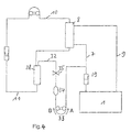
- FIG. 4 ties to the previous one Example, but offers additional features.
- the upper part the venous drip chamber 28 is connected via a line 32 in the a peristaltic pump 33 is inserted with the dialysis fluid system in connection.
- a Buffer vessel 34 inserted, e.g. in the form of an elastic bag with a volume of typically about 20-50 ml in the line section between the drip chamber and the buffer vessel 34, a valve 35 is inserted, preferably in the form of a Pinch valve.
- the patient-side connections of the arterial and the venous Blood tube connected together.
- the valve 35 is open.
- the pump 33 promotes in direction A. This creates as in the previous example in the blood tube system a negative pressure, so that filtered dialysis fluid through the membrane of the dialyzer 8 into the blood compartment. The promoted Air and the excess fluid get over the pump 33 in the dialysis fluid.
- the Dialysis membrane against the normal filtration direction periodically rinse, i. Deposits that are on the blood side have accumulated the membrane to remove. It is known, that such deposits, a so-called secondary membrane form and consist of substances that are the membrane can not happen, the effective diffusion resistance of the Enlarge the membrane and thereby increase the effectiveness of blood purification, especially with regard to the elimination of higher molecular weight Pollutants, reduce.
- the dialysis fluid system behaves in a volume-stable manner, such as in dialysis fluid systems with automatic balancing (For example, according to DE-OS 28 38 414) is the case.
- the valve 35 is constantly closed.
- the Pump 33 for a short time (a few seconds) with a relatively high conveying speed (on the order of 2-10 ml / s) in the direction A and transports liquid from the buffer vessel 34 in the dialysis fluid circuit. Due to the volume-rigid Behavior of the dialysis fluid system increases the pressure in the Dialysate compartment of the dialyzer on the pressure in the blood compartment on, so that a corresponding amount of liquid opposite the normal filtration direction into the blood passes and the deposited layers wash away. In the following Operating phase with normal filtration direction promotes the pump 33 slowly in the direction B and thus fills the buffer vessel 34 back up.
- Fig. 4 can also be used for this purpose will expand hemodialysis to hemodiafiltration, i.e. Hemodialysis with significantly increased ultrafiltration rate perform with simultaneous substitution of the largest Part of the withdrawn via the dialyzer amount of liquid Supply of an appropriate amount of a physiologically adapted Solution in the bloodstream. With appropriate choice of composition and ensured sterility of the dialysis fluid this can serve itself as a substitution fluid.
- the valve 35 is opened and the pump 33 operated with the conveying direction B.
- the conveying speed is typically at 1/3 - 1/5 of the conveying speed of the Blood pump 4 set.
- Dialysis fluid system behaves like a volume (automatically balancing system) is created by the action of the pump 33 in the dialysate compartment of the dialyzer an additional negative pressure, one of the conveying speed of the pump 33 corresponding Filtrate amount from the blood compartment into the dialysate compartment override.
- the overall filtrate balance will also be in this case not influenced by the described processes, but will, according to the operation of a balancing Dialysier remplikeitssystems, of the set Ultrafiltration rate determined.
- FIG. 4 can also be used for disinfecting and Rinse the dialyzer can be used. Such a cleaning cycle has the consequence that the dialyzer for reuse can be prepared. This is another essential Aspect of the present invention.
- a particularly useful combination is the application the periodic free purging of the dialyzer membrane in the Hemodiafiltration, according to the one described or another Process is carried out because, especially at the high filtration rates, used in hemodiafiltration the formation of a mass transfer inhibiting Secondary membrane is particularly pronounced.
Abstract
Description
Die Erfindung betrifft eine Anordnung zum Spülen und Befüllen eines extrakorporalen Blutkreislaufs von Dialysemaschinen, insbesondere von Blutschlauchleitungen und Dialysatoren. Das Befüllen beinhaltet dabei die Entlüftung des extrakorporalen Blutkreislaufs, die für eine Dialysebehandlung unabdingbare Voraussetzung ist.The invention relates to an arrangement for rinsing and filling a extracorporeal blood circulation of dialysis machines, in particular of Blood tubing and dialyzers. The filling includes the vent of the extracorporeal blood circulation required for a dialysis treatment indispensable condition.
Als arterielle und venöse Blutschlauchleitung eines extrakorporalen Blutkreislaufs werden heutzutage üblicherweise steril verpackte Einmalartikel verwendet, die vor einer Behandlung gespült, entlüftet und befüllt werden müssen. Dies geschieht bisher mittels physiologischer Kochsalzlösungen, die mittels der maschineneigenen Blutpumpe durch das Schlauchsystem und den Dialysator gefördert werden, um den extrakorporalen Blutkreis- lauf von Verunreinigungen freizuspülen und unter vollständiger Entlüftung zu befüllen.As arterial and venous blood tubing of an extracorporeal blood circulation Nowadays usually sterile packaged disposable articles are used, the before a treatment must be rinsed, vented and filled. this happens So far, by means of physiological saline solutions by means of the machine's own Blood pump through the tube system and the dialyzer are encouraged to Rinse the extracorporeal blood circulation of impurities and under to fill the complete vent.
Die Verwendung der Kochsalzspülflüssigkeit hat den Nachteil, daß sie mit erheblichen Kosten verbunden ist.The use of saline flushing liquid has the disadvantage that they are with considerable costs.
Die US-A-4552721 offenbart eine Anordnung zum Spülen und Befüllen eines extrakorporalen Blutkreislaufs von Dialysemaschinen, bei dem ein Beutel mit einer Kochsalzlösung an die arterielle Blutschlauchleitung angeschlossen ist. Die arterielle Blutschlauchleitung ist mit einer Blutpumpe verbunden und mit einer Tropfkammer versehen. Die arterielle Blutschlauchleitung und die venöse Blutschlauchleitung sind an dem Dialysator konnektiert, und in die venöse Blutschlauchleitung ist eine weitere Tropfkammer eingeschaltet. Von den oberen Enden der beiden Tropfkammern zweigen Leitungen zu einer Dialysesteuereinheit ab, um den Druck in den beiden Blutschlauchleitungen zu überwachen. Anschließend können die patientenseitigen Enden der Blutschlauchleitungen verbunden werden, um eine in den Hauptleitungen vorhandene Desinfektionsflüssigkeit auf alle Leitungsabschnitte verteilen zu können.US-A-4552721 discloses an arrangement for rinsing and filling a Extracorporeal blood circulation of dialysis machines, in which a bag with a Saline solution is connected to the arterial blood tubing. The arterial Blood tubing is connected to a blood pump and a drip chamber Provided. The arterial blood tubing and the venous blood tubing are connected to the dialyzer, and into the venous blood tubing is a switched on further drip chamber. From the upper ends of the two Drip chambers branch lines to a dialysis control unit to control the pressure to monitor in the two blood tubing lines. Subsequently, the Patient-side ends of the blood tubing are connected to a in the main lines existing disinfecting liquid on all line sections to be able to distribute.
Die EP-A-0228106 offenbart eine Vorrichtung zum Filtern von Plasma aus Blut, bei der eine arterielle und eine venöse Blutschlauchleitung an einem Plasma-Filter konnektiert sind und wobei dieser extrakorporale Blutkreislauf wie üblich mit Kochsalzlösung aus einem an eine Blutschlauchleitung angeschlossenen Beutel befüllt wird. Die andere Blutschlauchleitung ist mit einer Blutpumpe verbunden, die die Kochsalzlösung durch die Blutschlauchleitungen und den Plasma-Filter fördert, wobei in dem Plasma-Filter befindliche Luft aus dem patientenseitigen Ende der Blutschlauchleitung abgeführt wird.EP-A-0228106 discloses a device for filtering plasma from blood one arterial and one venous blood tubing to a plasma filter are connected and where this extracorporeal blood circulation as usual with Saline solution from a bag connected to a blood tubing is filled. The other blood tubing is connected to a blood pump, which promotes the saline solution through the blood tubing and the plasma filter, wherein in the plasma filter located air from the patient end of the Blood tube is discharged.
Die Frage einer Befüllung und Spülung mit einer intern verfügbaren Flüssigkeit wird in keinem der oben genannten Dokumente diskutiert.The question of filling and flushing with an internally available fluid is not discussed in any of the above documents.
Der vorliegenden Erfindung liegt die Aufgabe zugrunde, eine Anordnung anzugeben, mit der das Spülen, Entlüften und Befüllen eines extrakorporalen Blutkreislaufs von Dialysemaschinen vereinfacht ist.The present invention is based on the object, an arrangement indicate flushing, de-aerating and filling an extracorporeal blood circulation of dialysis machines is simplified.
Diese Aufgabe wird erfindungsgemäß durch die Merkmale der Ansprüche 1 und 2
gelöst. Vorteilhafte Weiterbildungen der Erfindung sind in den abhängigen Ansprüchen
gekennzeichnet.This object is achieved by the features of
Gemäß der Erfindung wird die von der Dialysemaschine erzeugte bzw. aufbereitete Dialysierflüssigkeit zum Zwecke des Spülens, Entlüftens und Befüllens durch den bzw. in den extrakorporalen Blutkreislauf gefördert. Hierdurch entfällt das bisherige Erfordernis, eine in einem Beutel abgefüllte Kochsalzlösung zu diesem Zweck bereit zu stellen, der zudem von einer Bedienungsperson an die arterielle Blutschlauchleitung anzuschließen war. Es entfällt damit ferner das Erfordernis, zu dem genannten Zweck Kochsalzlösungen in größeren Mengen bereit zu halten und die geleerten Beutel zu entsorgen.According to the invention, the generated or processed by the dialysis machine Dialysis fluid for the purpose of purging, venting and filling by the or promoted in the extracorporeal blood circulation. This eliminates the previous one Requirement to prepare a bagged saline solution for this purpose In addition, from an operator to the arterial Blood tubing was to be connected. It also eliminates the requirement to to keep the above-mentioned purpose saline solutions in larger quantities ready and to dispose of the emptied bags.
Gemäß der Erfindung wird die Dialysierflüssigkeit blutseitig des Dialysators abgenommen, wobei sie beim Durchtritt durch die Membran filtiert wird. Hiermit ist die Keimfreiheit der Spül- und Befüllflüssigkeit zuverlässig gewährleistet.According to the invention, the dialysis fluid on the blood side of the dialyzer taken, whereby it is filtered as it passes through the membrane. Hereby is reliably ensures the sterility of the rinsing and filling liquid.
Nach einem Aspekt der Erfindung wird die dem Dialysator entnommene Dialysierflüssigkeit von der maschineneigenen Blutpumpe durch den extrakorporalen Blutkreislauf gepumpt. Das Blutpumpensegment der arteriellen Blutschlauchleitung wird in die maschineneigene Blutpumpe, vorzugsweise eine Rollerpumpe, eingelegt.In one aspect of the invention, the dialyser is removed Dialysis fluid from the machine's own blood pump through the extracorporeal Pumped blood circulation. The blood pump segment of the arterial blood tubing is in the machine's own blood pump, preferably a roller pump, inserted.
Wenn die Blutpumpe in Betrieb gesetzt wird, wird Dialysierflüssigkeit über die semipermeable Membran des Dialysators in die Blutschlauchleitungen gezogen. Dabei gelangt nur sterile und keimfreie Spülflüssigkeit in den extrakorporalen Blutkreislauf.When the blood pump is put into operation, dialysis fluid is passed over the semipermeable membrane of the dialyzer pulled into the blood tubing. Only sterile and germ-free rinsing fluid gets into the extracorporeal Blood flow.
Die Erfindung sieht vor, daß nach dem Konnektieren der arteriellen und venösen Blutschlauchleitung am Dialysator die Patientenanschlüsse dieser beiden Leitungen miteinander verbunden werden, um eine durchgehende Flüssigkeitsleitung zu bilden, daß der Strömungsweg zwischen dem venösen Blutanschluß des Dialysators und der zur Entlüftung vorzugsweise vorgesehenen venösen Tropfkammer gesperrt wird, daß die Blutpumpe entgegen ihrer normalen Förderrichtung in Betrieb gesetzt wird, und daß die aus dem Blutschlauchsystem verdrängte Luft und überschüssige Flüssigkeit durch eine mit dem oberen Teil der venösen Tropfkammer verbundene Leitung abgeleitet wird. Dabei kann vorgesehen sein, daß die verdrängte Luft und die überschüssige Flüssigkeit in das Dialysierflüssigkeitsystem des Dialysegerätes abgeführt werden.The invention provides that after connecting the arterial and venous Blood tubing on the dialyzer patient connections of these two lines connected to each other to a continuous liquid line form that flow path between the venous blood port of the dialyzer and blocked for venting preferably provided venous drip chamber is that the blood pump against its normal conveying direction in operation is set, and that the displaced from the blood hose system air and excess fluid through one with the upper part of the venous drip chamber derived line is derived. It can be provided that the displaced air and the excess fluid in the dialysis fluid system be discharged from the dialysis machine.
Dies kann dadurch weiter ausgestaltet werden, daß intermittierend die normalen Strömungsverhältnisse des extrakorporalen Blutkreislaufs hergestellt werden, d.h. Öffnen des Strömungsweges zwischen dem venösen Blutanschluß des Dialysators und der venösen Tropfkammer und Inbetriebsetzen der Blutpumpe in ihrer normalen Förderrichtung, wobei die mit dem oberen Teil der venösen Tropfkammer verbundene Leitung verschlossen ist. This can be further developed by intermittently the normal Flow conditions of the extracorporeal blood circulation are produced, i. Opening the flow path between the venous blood port of the dialyzer and the venous drip chamber and putting the blood pump in its normal Direction of delivery, with the upper part of the venous drip chamber Connected line is closed.
Das Umschalten der Ventile und der Förderrichtung der Blutpumpe kann über ein automatisch ablaufendes Programm im Rahmen des Steuerungsprogramms des Dialysegerätes bewirkt werden.The switching of the valves and the conveying direction of the blood pump can via a automatically running program as part of the control program of the Dialysis machine be effected.
Nach einem alternativen Aspekt der Erfindung werden wiederum der arterielle und der venöse Patientenanschluß der Blutschlauchleitungen zur Schaffung einer durchgehenden Flüssigkeitsleitung miteinander verbunden, und eine an den oberen Teil der venösen Tropfkammer angeschlossene Leitung wird mit einer Saugvorrichtung versehen bzw. verbunden. Hierbei kann als Saugvorrichtung das Entgasungssystem des Dialysegerätes verwendet werden, wobei alternativ eine Pumpe angeordnet sein kann, deren abfördernde Leitung mit dem Dialysierflüssigkeitssystem verbunden sein kann.According to an alternative aspect of the invention turn the arterial and the venous patient port of the blood tubing to provide a continuous Liquid line connected to each other, and one to the upper part the venous drip chamber is connected to a suction device provided or connected. Here, as a suction device, the degassing system be used of the dialysis machine, wherein alternatively arranged a pump may be, whose discharge line connected to the dialysis fluid system can be.
In weiterer Ausgestaltung kann vorgesehen sein, daß in der Dialysatkammer des Dialysators in vorgegebenen Zeitabständen ein erhöhter Druck erzeugt wird, der den Druck in der Blutkammer des Dialysators übersteigt und eine Filtration von Dialysierflüssigkeit in das Blut bewirkt. Dieser nach dem Anschließen eines Patienten und dem Beginn der eigentlichen Behandlung erfolgende Vorgang dient dazu, die Dialysemembran entgegen der normalen Filtrationsrichtung periodisch freizuspülen, d. h. Ablagerungen, die sich auf der Blutseite der Membran angesammelt haben, zu entfernen.In a further embodiment it can be provided that in the dialysate chamber of the Dialysers at predetermined intervals an increased pressure is generated, the exceeds the pressure in the blood chamber of the dialyzer and a filtration of Dialysis fluid into the blood causes. This after connecting a Patients and the beginning of the actual treatment process takes place in addition, the dialysis membrane against the normal filtration direction periodically rinse, d. H. Deposits that are on the blood side of the membrane have accumulated to remove.
Vorzugsweise wird hierbei ein volumenstarr wirkendes Dialysierflüssigkeitssystem verwendet, wodurch die Möglichkeit geschaffen ist, daß eine periodische Druckerhöhung und Druckabsenkung mit der Pumpe bewirkt wird, die abwechselnd zusätzliche Flüssigkeit in das Dialysierflüssigkeitssystem einführt bzw. dem Dialysierflüssigkeitssystem Flüssigkeit entzieht, was in näheren Einzelheiten weiter unten noch beschrieben wird.Preferably, in this case is a dialysis liquid system which acts with a solid volume used, whereby the possibility is created that a periodic Pressure increase and pressure reduction is effected with the pump, which alternately introduces additional liquid in the dialysis fluid or the Dialysis fluid system deprives fluid, which continues in more detail will be described below.
Erfindungsgemäß kann diese Vorgehensweise in Verbindung mit einer Hämodiafiltration angewendet werden. According to the invention, this procedure can be combined with hemodiafiltration be applied.
Nach einem zusätzlichen Vorschlag der Erfindung ist vorgesehen, daß ein Sterilfilter stromaufwärts des Dialysators in dem Dialysierflüssigkeitskreislauf angeordnet wird, um die Sicherheit in Bezug auf die erforderliche Keimfreiheit zusätzlich zu erhöhen.According to an additional proposal of the invention is provided a sterile filter upstream of the dialyzer in the dialysis fluid circuit is arranged to safety in In addition to increase the required sterility in addition.
Nach einem weiteren Gesichtspunkt der Erfindung wird vorgeschlagen, daß die als Spülflüssigkeit verwendete Dialysierflüssigkeit nach Beendigung einer Dialysebehandlung zur Freispülung des extrakorporalen Blutkreislaufes verwendet wird, wozu es zweckmäßig ist, diese Flüssigkeit beim Spülvorgang in einen Beutel abzuführen. Das Freispülen ist notwendig, um nach der Dialysebehandlung das Blut vollständig zum Patienten zurückzuführen, was bisher ebenfalls mit Hilfe einer Kochsalzlösung geschieht.According to a further aspect of the invention, it is proposed that the dialysis fluid used as rinsing fluid after completion of a dialysis treatment to rinse the Extracorporeal blood circulation is used, for which purpose is, this liquid during rinsing in a bag dissipate. The rinsing off is necessary after the dialysis treatment the blood completely returned to the patient, what previously also done with the help of a saline solution.
Nach einem weiteren Vorschlag der Erfindung verbindet eine Leitung den oberen Teil der venösen Tropfkammer und das Dialysierflüssigkeitssystem, wobei diese Leitung mit einer Pumpe und zwischen dieser Pumpe und dem oberen Teil der venösen Tropfkammer mit einem Puffergefäß sowie einem Ventil zum Öffnen/Schließen des Leitungsabschnitts zwischen dem Puffergefäß und der venösen Tropfkammer versehen ist.According to another proposal of the invention connects a Lead the upper part of the venous drip chamber and the dialysis fluid system, being this line with a pump and between this pump and the upper part of the venous drip chamber with a buffer vessel and a valve for opening / closing the line section between the buffer vessel and the venous drip chamber is provided.
Ein weiterer erfindungsgemäßer Vorschlag geht dahin, die extrakorporalen Komponenten so zu reinigen, daß sie wiederverwendbar sind. Hierzu kann die Anordnung so getroffen werden, wie sie weiter oben im Zusammenhang mit der ersten Ausführungsform beschrieben ist. Bei einem dialysemaschinenspezifischen Reinigungsprogramm wird durch die Förderung der Blutpumpe Reinigungsflüssigkeit über die semipermeable Membran des Dialysators in den extrakorporalen Kreislauf gezogen, wodurch dieser entsprechend gereinigt wird. Another proposal according to the invention goes there, the extracorporeal Clean components so that they are reusable are. For this purpose, the arrangement can be made as above in connection with the first embodiment is described. In a dialysis machine specific cleaning program is by the promotion of the blood pump cleaning fluid via the semipermeable membrane of the dialyzer in pulled the extracorporeal circuit, making this accordingly is cleaned.
Selbstverständlich liegt es im Rahmen der Erfindung, die extrakorporalen Komponeten weiterhin als Einmalartikel einzusetzen.Of course, it is within the scope of the invention, the extracorporeal Continue to use components as disposables.
Der Grundgedanke der Erfindung, die von einer Dialysemaschine erzeugte bzw. aufbereitete Dialyseflüssigkeit zum Spülen und Befüllen eines extrakorporalen Blutkreislaufs von Dialysemaschinen zu verwenden, ist grundsätzlich auch dadurch zu verwirklichen, daß die Dialyseflüssigkeit nicht die Membran des Dialysators passiert, sondern in Strömungsrichtung hinter einer Filtereinrichtung, beispielsweise dem weiter unten beschriebenen Sterilfilter des Dialysierflüssigkeitskreislaufs entnommen bzw. abgezweigt und in das auf geeignete Weise angeschlossene Blutschlauchsystem eingeführt wird.The basic idea of the invention, that of a dialysis machine produced or prepared dialysis fluid for rinsing and Filling an extracorporeal blood circulation of dialysis machines to use in principle is also to be realized thereby, that the dialysis fluid is not the membrane of the dialyzer happens, but in the flow direction behind a filter device, for example, the one described below Sterile filter of Dialysierflüssigkeitskreislaufs removed or branched off and in the appropriately connected blood hose system is introduced.
Weitere Merkmale, Vorteile und Einzelheiten der Erfindung ergeben sich aus der nachfolgenden Beschreibung einiger bevorzugter Ausführungsformen sowie anhand der Zeichnung. Dabei zeigen auf rein schematische Weise:
- Fig. 1
- eine herkömmliche Anordnung;
- Fig. 2
- eine erste Ausführungsform der erfindungsgemäßen Anordnung;
- Fig. 3
- eine zweite Ausführungsform der erfindungsgemäßen Anordnung;
- Fig. 4
- eine dritte Ausführungsform der erfindungsgemäßen Anordnung.
- Fig. 1
- a conventional arrangement;
- Fig. 2
- a first embodiment of the inventive arrangement;
- Fig. 3
- a second embodiment of the arrangement according to the invention;
- Fig. 4
- a third embodiment of the arrangement according to the invention.
Es wird zunächst auf Fig. 1 Bezug genommen, um das bisher übliche
Verfahren zum Spülen, Entlüften und Befüllen eines extrakorporalen
Blutkreislaufs zu erläutern. Die Fig. zeigt eine
eigentliche Dialysemaschine 1 mit der oberen Überwachungsebene
2, der mittleren Ebene 3, die eine Blutpumpe 4 und einen Luftdetektor
5 enthält, und mit einer unteren Ebene 6, die den
Hydraulikteil aufweist.Reference is first made to Fig. 1, to the previously usual
Method for rinsing, venting and filling an extracorporeal
To explain blood circulation. The figure shows a
Die Dialysemaschine 1 ist über eine Zuleitung 7 mit dem Dialysator
8 verbunden, von dem eine Rückleitung 9 zur Dialysemaschine
1 zurückführt, um einen Dialysierflüssigkeitskreislauf zu
schließen.The
Zum Zwecke einer Dialysebehandlung werden eine arterielle
Blutschlauchleitung 10 und eine venöse Blutschlauchleitung 11 an
den dargestellten Stellen an dem Dialysator 8 konnektiert. Ein
Blutpumpensegment 12 der arteriellen Blutschlauchleitung 10 wird
in die Blutpumpe 4 eingelegt, während die venöse Blutschlauchleitung
11 über den Luftdetektor 5 führt.For the purpose of dialysis treatment, an
Zur Vorbereitung einer Dialysebehandlung müssen die Blutschlauchleitungen
10 und 11 freigespült werden und der extrakorporale
Blutkreislauf muß entlüftet und befüllt werden. Hierzu
ist es bisher üblich, das freie Ende der arteriellen Blutschlauchleitung
10 mit dem Ausgang eines eine Kochsalzlösung
enthaltenden Beutels 13 zu verbinden. Die Blutpumpe 4 fördert
die Kochsalzlösung durch die arterielle Blutschlauchleitung 10,
den Dialysator 8, die venöse Blutschlauchleitung 11 und den
Luftdetektor 5, um schließlich die Spülflüssigkeit in einen
offenen Behälter 14 abzuführen.To prepare for a dialysis treatment, the blood tubing must
10 and 11 are rinsed free and the extracorporeal
Blood circulation must be vented and filled. For this
It has been customary to date the free end of the
Es wird nun auf die Fig. 2 bis 4 Bezug genommen, in denen die Bauteile, die mit denjenigen gemäß Fig. 1 übereinstimmen, mit denselben Bezugszeichen gekennzeichnet sind. Auf ihre Wiederholung wird aus Gründen der Übersichtlichkeit verzichtet. Referring now to Figs. 2 to 4, in which the Components that match those shown in FIG. 1, with the same reference numerals. On her repetition is omitted for reasons of clarity.
Gemäß Fig. 2 sind bei dem Füll- und Spülvorgang die patientenseitigen
Anschlüsse des areriellen und des venösen Blutschlauches
10, 11 miteinander verbunden. In die venöse Blutleitung 11
zwischen dem Dialysator 8 und der venösen Tropfkammer 28 ist ein
Ventil 29 in Form einer Schlauchklemme eingefügt. Vom oberen
Teil der venösen Tropfkammer 28 zweigt eine ebenfalls mit einem
Ventil 30 ausgestattete Leitung ab, die mit einem Auffanggefäß
oder, wie in Fig. 2 dargestellt, mit dem Dialysierflüssigkeitssystem
verbunden ist.According to FIG. 2, the patient-side are in the filling and rinsing process
Connections of the arterial and
Zum Zwecke des Füllens und Spülens des extrakorporalen Blutkreislaufes
wird die Blutpumpe 4 entgegen ihrer normalen Förderrichtung
(Richtungspfeil 1 A) in Tätigkeit gesetzt (z.B. durch
Ändern ihrer Drehrichtung), das Ventil 29 wird geschlossen und
das Ventil 30 geöffnet.For the purpose of filling and rinsing the extracorporeal blood circulation
the
Durch die Tätigkeit der Blutpumpe entsteht im Blutkompartiment
des Dialysators 8 ein Unterdruck. Dadurch tritt filtrierte
Dialysierflüssigkeit in das Blutkompartiment und das Blutschlauchsystem
über, so daß dieses in kurzer Zeit gefüllt wird.
Die abgepumpte Luft und nachfolgende Flüssigkeit werden über das
geöffnete Ventil 30 in das Dialysierflüssigkeitssystem gefördert.Through the activity of the blood pump arises in the blood compartment
the
Dieses Verfahren kann zur Intensivierung des Spülvorgangs noch
dadurch ergänzt werden, daß zwischenzeitlich mehrfach das Ventil
29 geöffnet wird (bei gleichzeitigem oder zeitlich versetztem
Schließen des Ventils 30) und bei Bedarf zusätzlich die Blutpumpe
in ihrer normalen Förderrichtung (entgegen dem Richtungspfeil
A) arbeitet. This procedure can be used to intensify the rinsing process
be supplemented by that meanwhile several times the
Die genannten Umschaltungen der Ventile 29, 30 und der Förderrichtung
der Blutpumpe 4 können ohne weiteres über ein automatisch
ablaufendes Programm im Rahmen des Steuerungsprogramms des
Dialysegerätes bewirkt werden, so daß sich eine erhebliche
Arbeitsvereinfachung erreichen läßt.The said switching of the
Fig. 3 zeigt ein weiteres Ausführungsbeispiel. Die patientenseitigen
Anschlüsse der Blutschläuche sind zum Zwecke des Füllens
und Spülens des extrakorporalen Blutkreislaufes miteinander
verbunden. Eine vom oberen Teil der venösen Tropfkammer abzweigende
Leitung steht mit einer Saugvorrichtung 31 in Verbindung,
die dazu dient, im gesamten extrakorporalen Leitungssystem,
einschließlich des Blutkompartiments des Dialysators 8, einen
Unterdruck zu erzeugen, so daß filtrierte Dialysierflüssigkeit
in das Blutkompartiment übertritt. Bei eingeschalteter Blutpumpe
4 zirkuliert diese Flüssigkeit dann durch den gesamten Kreislauf.
Luft und überschüssige Flüssigkeit werden über die vom
oberen Teil der venösen Tropfkammer abzweigende Leitung abgeführt.Fig. 3 shows another embodiment. The patient side
Connections of the blood tubes are for the purpose of filling
and rinsing the extracorporeal blood circulation with each other
connected. A branching off from the upper part of the venous drip chamber
Line communicates with a
Die Saugvorrichtung 31 kann eine externe Saugvorrichtung sein,
z.B. unter Benutzung des in Krankenhäusern häufig verfügbaren
Vakuum-Leitungsnetzes, ggf. mit einem zwischengeschalteten
Flüssigkeitsabscheider, oder sie kann als Pumpe ausgebildet
sein, wobei die austretende Flüssigkeit in einem Auffanggefäß
gesammelt oder in das Dialysierflüssigkeitssystem abgeleitet
werden kann. Eine besonders einfache und damit vorteilhafte
Anordnung ergibt sich, wenn als Saugvorrichtung das Entgasungssystem
des Dialysegerätes mitbenutzt wird. Dabei handelt es sich
bei den meisten Dialysegeräten um eine Pumpe, die in einem
Teilabschnitt der stromabwärts von ihr liegenden Fließstrecke
einen starken Unterdruck erzeugt, um überschüssig gelöstes Gas
zur Ausscheidung zu bringen. Die Saugtätigkeit dieser Pumpe kann
für den oben beschriebenen Zweck genutzt werden, indem man eine
Leitungsverbindung zwischen dem oberen Teil der venösen Tropfkammer
und dem genannten Teilabschnitt herstellt. The
Das Ausführungsbeispiel nach Fig. 4 knüpft an das vorhergehende
Beispiel an, bietet aber zusätzliche Funktionen. Der obere Teil
der venösen Tropfkammer 28 steht über eine Leitung 32, in die
eine Schlauchpumpe 33 eingefügt ist, mit dem Dialysierflüssigkeitssystem
in Verbindung. In den Leitungsabschnitt zwischen der
venösen Tropfkammer 28 und dieser Pumpe 33 ist außerdem ein
Puffergefäß 34 eingefügt, z.B. in Form eines elastischen Beutels
mit einem Volumen von typischerweise etwa 20-50 ml. Außerdem ist
in den Leitungsabschnitt zwischen der Tropfkammer und dem Puffergefäß
34 ein Ventil 35 eingefügt, vorzugsweise in Form eines
Schlauchklemmventils.The embodiment of FIG. 4 ties to the previous one
Example, but offers additional features. The upper part
the
Zum Füllen und Spülen des extrakorporalen Blutkreislaufs sind
die patientenseitigen Anschlüsse des arteriellen und des venösen
Blutschlauches miteinander verbunden. Das Ventil 35 ist geöffnet.
Die Pumpe 33 fördert in Richtung A. Dadurch entsteht wie
bei dem vorhergehenden Beispiel im Blutschlauchsystem ein Unterdruck,
so daß filtrierte Dialysierflüssigkeit durch die Membran
des Dialysators 8 in das Blutkompartiment übertritt. Die abgeförderte
Luft und die überschüssige Flüssigkeit gelangen über
die Pumpe 33 in das Dialysierflüssigkeitssystem.For filling and rinsing the extracorporeal blood circulation are
the patient-side connections of the arterial and the venous
Blood tube connected together. The
Nach dem Anschließen des Patienten und dem Beginn der eigentlichen
Behandlung dient die in Fig. 4 gezeigte Anordnung dazu, die
Dialysemembran entgegen der normalen Filtrationsrichtung periodisch
freizuspülen, d.h. Ablagerungen, die sich auf der Blutseite
der Membran angesammelt haben, zu entfernen. Es ist bekannt,
daß solche Ablagerungen, die eine sogenannte Sekundarmembran
bilden und aus Substanzen bestehen, die die Membran
nicht passieren können, den effektiven Diffusionswiderstand der
Membran vergrößern und dadurch die Effektivität der Blutreinigung,
insbesondere hinsichtlich der Ausscheidung höhermoleklarer
Schadstoffe, vermindern. Im folgenden wird vorausgesetzt, daß
das Dialysierflüssigkeitssystem sich volumenstarr verhält, wie
es bei Dialysierflüssigkeitssystemen mit automatischer Bilanzierung
(z.B. nach DE-OS 28 38 414) der Fall ist. Das Ventil 35 ist
ständig geschlossen. Zum Freispülen der Dialysemembran läuft die
Pumpe 33 kurze Zeit (einige Sekunden) mit relativ hoher Fördergeschwindigkeit
(in der Größenordnung von 2-10 ml/s) in Richtung
A und transportiert Flüssigkeit aus dem Puffergefäß 34 in
den Dialysierflüssigkeitskreislauf. Aufgrund des volumenstarren
Verhaltens des Dialysierflüssigkeitssystems steigt der Druck im
Dialysatkompartiment des Dialysators über den Druck im Blutkompartiment
an, so daß eine entsprechende Flüssigkeitsmenge entgegen
der normalen Filtrationsrichtung in das Blut übertritt und
die aufgelagerten Schichten abschwemmt. In der darauffolgenden
Betriebsphase mit normaler Filtrationsrichtung fördert die Pumpe
33 langsam in Richtung B und füllt damit das Puffergefäß 34
wieder auf. Nach einer gewissen Zeit wird die Pumpe wieder in
Richtung A in Tätigkeit gesetzt, um das nächste Freispülen der
Dialysatormembran einzuleiten. Die Häufigkeit des Freispülens
der Dialysatormembran kann nach Bedarf verändert werden. Die
Gesamtfiltratbilanz wird von den beschriebenen Vorgängen übrigens
nicht beeinflußt, sondern wird, entsprechend der Funktionsweise
eines bilanzierenden Dialysierflüssigkeitssystems, von der
eingestellten Ultrafiltrationsrate bestimmt.After connecting the patient and the beginning of the actual
Treatment serves the arrangement shown in Fig. 4, the
Dialysis membrane against the normal filtration direction periodically
rinse, i. Deposits that are on the blood side
have accumulated the membrane to remove. It is known,
that such deposits, a so-called secondary membrane
form and consist of substances that are the membrane
can not happen, the effective diffusion resistance of the
Enlarge the membrane and thereby increase the effectiveness of blood purification,
especially with regard to the elimination of higher molecular weight
Pollutants, reduce. In the following it is assumed that
the dialysis fluid system behaves in a volume-stable manner, such as
in dialysis fluid systems with automatic balancing
(For example, according to DE-OS 28 38 414) is the case. The
Die in Fig. 4 gezeigte Anordnung kann darüberhinaus dazu genutzt
werden, die Hämodialyse zu einer Hämodiafiltration zu erweitern,
d.h. eine Hämodialyse mit wesentlich erhöhter Ultrafiltrationsrate
durchzuführen bei gleichzeitiger Substitution des größten
Teils der über den Dialysator entzogenen Flüssigkeitsmenge durch
Zufuhr einer entsprechenden Menge einer physiologisch angepaßten
Lösung in den Blutkreislauf. Bei entsprechender Wahl der Zusammensetzung
und gewährleisteter Sterilität der Dialysierflüssigkeit
kann diese selbst als Substitutionsflüssigkeit dienen.
Zu dem genannten Zweck wird das Ventil 35 geöffnet und die Pumpe
33 mit der Förderrichtung B betrieben. Die Fördergeschwindigkeit
wird typischerweise auf 1/3 - 1/5 der Fördergeschwindigkeit der
Blutpumpe 4 eingestellt. Unter der Voraussetzung, daß sich das
Dialysierflüssigkeitssystem volumenstarr verhält (automatisch
bilanzierendes System) entsteht durch die Tätigkeit der Pumpe 33
im Dialysatkompartiment des Dialysators ein zusätzlicher Unterdruck,
der eine der Fördergeschwindigkeit der Pumpe 33 entsprechende
Filtratmenge aus dem Blutkompartiment in das Dialysatkompartiment
übergehen läßt. Die Gesamt-Filtratbilanz wird auch
in diesem Falle von den beschriebenen Vorgängen nicht beeinflußt,
sondern wird, entsprechend der Funktionsweise eines
bilanzierenden Dialysierflüssigkeitssystems, von der eingestellten
Ultrafiltrationsrate bestimmt.The arrangement shown in Fig. 4 can also be used for this purpose
will expand hemodialysis to hemodiafiltration,
i.e. Hemodialysis with significantly increased ultrafiltration rate
perform with simultaneous substitution of the largest
Part of the withdrawn via the dialyzer amount of liquid
Supply of an appropriate amount of a physiologically adapted
Solution in the bloodstream. With appropriate choice of composition
and ensured sterility of the dialysis fluid
this can serve itself as a substitution fluid.
For the stated purpose, the
Die Anordnung gemäß Fig. 4 kann auch zum Desinfizieren und Spülen des Dialysators verwendet werden. Ein solcher Reinigungszyklus hat zur Folge, daß der Dialysator zur Wiederverwendung aufbereitet werden kann. Dies ist ein weiterer wesentlicher Gesichtspunkt der vorliegenden Erfindung.The arrangement of FIG. 4 can also be used for disinfecting and Rinse the dialyzer can be used. Such a cleaning cycle has the consequence that the dialyzer for reuse can be prepared. This is another essential Aspect of the present invention.
Die beschriebenen Funktionen können miteinander kombiniert werden. Eine besonders sinnvolle Kombination ist die Anwendung des periodischen Freispülens der Dialysatormembran bei der Hämodiafiltration, die nach dem beschriebenen oder einem anderen Verfahren durchgeführt wird, weil gerade bei den hohen Filtrationsgeschwindigkeiten, die bei der Hämodiafiltration zur Anwendung gelangen, die Bildung einer den Stoffaustausch hemmenden Sekundärmembran besonders ausgeprägt ist.The described functions can be combined with each other become. A particularly useful combination is the application the periodic free purging of the dialyzer membrane in the Hemodiafiltration, according to the one described or another Process is carried out because, especially at the high filtration rates, used in hemodiafiltration the formation of a mass transfer inhibiting Secondary membrane is particularly pronounced.
Auch andere Teilaspekte der beschriebenen Beispiele können, für den Fachmann leicht ersichtlich, sinnvoll kombiniert werden und durch andere, an sich bekannte Maßnahmen ergänzt werden.Other aspects of the examples described can, for readily apparent to those skilled in the art, can be meaningfully combined and be supplemented by other measures known per se.
Claims (6)
- Apparatus for the on-line flushing and filling of an extracorporeal blood circuit of dialysis machines with dialysate liquid, particularly of blood hose lines and dialysers, wherein the arterial and venous blood hose lines (10, 11) are connected to the dialyser (8), the patient connections of the two lines (10, 11) are connected together, a drip chamber (28) is arranged in the venous blood hose line, a valve (29) is arranged in the venous blood hose line (11) between the drip chamber (28) and the dialyser (8), a line branches off from the upper portion of the drip chamber (28) which serves to conduct away the air displaced from the blood hose system and excess liquid and wherein a blood hose line (10) is connected to a blood pump (4).
- Apparatus for the on-line flushing and filling of an extracorporeal blood circuit of dialysis machines with dialysate liquid, particularly of blood hose lines and dialysers, wherein the arterial and venous blood hose lines (10, 11) are connected to the dialyser (8), the patient connections of the two lines (10, 11) are connected together, a drip chamber (28) is arranged in the venous blood hose line, a line branches off from the upper portion of the drip chamber (28) which serves to conduct away the air displaced from the blood hose system and excess liquid and wherein the branch line is connected to a suction device.
- Apparatus as claimed in Claim 1 or 2, characterised in that arranged in the line branching off from the upper portion of the drip chamber (28) there is a valve (30, 35).
- Apparatus as claimed in one of Claims 1 to 3, characterised in that the branch line is connected to the dialysis liquid system.
- Apparatus as claimed in one of Claims 1 to 3, characterised in that the branch line is connected to a collecting vessel.
- Apparatus as claimed in one of Claims 2 to 4, characterised in that arranged in the branch line (32) there is a pump (33), a buffer vessel (34) connected between the pump (33) and the upper portion of the venous drip chamber (28) and a valve (35) for opening/closing the section of the line between the buffer vessel (34) and the venous drip chamber (28).
Priority Applications (1)
| Application Number | Priority Date | Filing Date | Title |
|---|---|---|---|
| EP03005856A EP1323439B1 (en) | 1992-03-13 | 1993-03-11 | Device for on-line cleaning and filling or emptying of an extra corporeal blood circuit of a dialysis apparatus |
Applications Claiming Priority (4)
| Application Number | Priority Date | Filing Date | Title |
|---|---|---|---|
| DE4208274 | 1992-03-13 | ||
| DE4208274A DE4208274C1 (en) | 1992-03-13 | 1992-03-13 | Method and arrangement for rinsing and filling the extracorporeal blood circuit of dialysis machines |
| EP93103965A EP0560368B1 (en) | 1992-03-13 | 1993-03-11 | Process for on-line cleaning and filling of an extra corporeal blood circuit of a dialysis apparatus |
| EP96103982A EP0720856B1 (en) | 1992-03-13 | 1993-03-11 | Device for on-line cleaning and filling of an extracorporal blood circuit of a dialysis apparatus |
Related Parent Applications (1)
| Application Number | Title | Priority Date | Filing Date |
|---|---|---|---|
| EP96103982A Division EP0720856B1 (en) | 1992-03-13 | 1993-03-11 | Device for on-line cleaning and filling of an extracorporal blood circuit of a dialysis apparatus |
Related Child Applications (1)
| Application Number | Title | Priority Date | Filing Date |
|---|---|---|---|
| EP03005856A Division EP1323439B1 (en) | 1992-03-13 | 1993-03-11 | Device for on-line cleaning and filling or emptying of an extra corporeal blood circuit of a dialysis apparatus |
Publications (3)
| Publication Number | Publication Date |
|---|---|
| EP0826383A2 EP0826383A2 (en) | 1998-03-04 |
| EP0826383A3 EP0826383A3 (en) | 1998-03-11 |
| EP0826383B1 true EP0826383B1 (en) | 2004-08-25 |
Family
ID=6454118
Family Applications (5)
| Application Number | Title | Priority Date | Filing Date |
|---|---|---|---|
| EP97118498A Expired - Lifetime EP0826383B1 (en) | 1992-03-13 | 1993-03-11 | Device for on-line cleaning and filling of an extra corporeal blood circuit of a dialysis apparatus |
| EP93103965A Expired - Lifetime EP0560368B1 (en) | 1992-03-13 | 1993-03-11 | Process for on-line cleaning and filling of an extra corporeal blood circuit of a dialysis apparatus |
| EP97118499A Expired - Lifetime EP0826384B1 (en) | 1992-03-13 | 1993-03-11 | Arrangement for on-line cleaning and filling of an extra corporeal blood circuit of a dialysis apparatus |
| EP03005856A Revoked EP1323439B1 (en) | 1992-03-13 | 1993-03-11 | Device for on-line cleaning and filling or emptying of an extra corporeal blood circuit of a dialysis apparatus |
| EP96103982A Expired - Lifetime EP0720856B1 (en) | 1992-03-13 | 1993-03-11 | Device for on-line cleaning and filling of an extracorporal blood circuit of a dialysis apparatus |
Family Applications After (4)
| Application Number | Title | Priority Date | Filing Date |
|---|---|---|---|
| EP93103965A Expired - Lifetime EP0560368B1 (en) | 1992-03-13 | 1993-03-11 | Process for on-line cleaning and filling of an extra corporeal blood circuit of a dialysis apparatus |
| EP97118499A Expired - Lifetime EP0826384B1 (en) | 1992-03-13 | 1993-03-11 | Arrangement for on-line cleaning and filling of an extra corporeal blood circuit of a dialysis apparatus |
| EP03005856A Revoked EP1323439B1 (en) | 1992-03-13 | 1993-03-11 | Device for on-line cleaning and filling or emptying of an extra corporeal blood circuit of a dialysis apparatus |
| EP96103982A Expired - Lifetime EP0720856B1 (en) | 1992-03-13 | 1993-03-11 | Device for on-line cleaning and filling of an extracorporal blood circuit of a dialysis apparatus |
Country Status (7)
| Country | Link |
|---|---|
| US (2) | US5259961A (en) |
| EP (5) | EP0826383B1 (en) |
| AT (5) | ATE206939T1 (en) |
| DE (6) | DE4208274C1 (en) |
| DK (1) | DK0560368T3 (en) |
| ES (5) | ES2300514T3 (en) |
| GR (3) | GR3026703T3 (en) |
Cited By (3)
| Publication number | Priority date | Publication date | Assignee | Title |
|---|---|---|---|---|
| US8114276B2 (en) | 2007-10-24 | 2012-02-14 | Baxter International Inc. | Personal hemodialysis system |
| US8834403B2 (en) | 2007-10-01 | 2014-09-16 | Baxter International Inc. | Fluid and air handling in blood and dialysis circuits |
| US9486590B2 (en) | 2014-09-29 | 2016-11-08 | Fenwal, Inc. | Automatic purging of air from a fluid processing system |
Families Citing this family (51)
| Publication number | Priority date | Publication date | Assignee | Title |
|---|---|---|---|---|
| US5902476A (en) * | 1991-08-21 | 1999-05-11 | Twardowski; Zbylut J. | Artificial kidney for frequent (daily) hemodialysis |
| US5336165A (en) * | 1991-08-21 | 1994-08-09 | Twardowski Zbylut J | Artificial kidney for frequent (daily) Hemodialysis |
| US5910252A (en) * | 1993-02-12 | 1999-06-08 | Cobe Laboratories, Inc. | Technique for extracorporeal treatment of blood |
| US5591344A (en) * | 1995-02-13 | 1997-01-07 | Aksys, Ltd. | Hot water disinfection of dialysis machines, including the extracorporeal circuit thereof |
| IT1279572B1 (en) † | 1995-05-30 | 1997-12-16 | Hospal Dasco Spa | METHOD AND APPARATUS FOR WASHING A FILTER FOR DIALYSIS. |
| US5685835A (en) * | 1995-06-07 | 1997-11-11 | Cobe Laboratories, Inc. | Technique for using a dialysis machine to disinfect a blood tubing set |
| US5772624A (en) * | 1995-07-20 | 1998-06-30 | Medisystems Technology Corporation | Reusable blood lines |
| SE510127C2 (en) | 1996-06-13 | 1999-04-19 | Althin Medical Ab | Disposable Hemodia Filtration Kit |
| US6331252B1 (en) * | 1998-07-31 | 2001-12-18 | Baxter International Inc. | Methods for priming a blood compartment of a hemodialyzer |
| DE19835294C1 (en) * | 1998-08-05 | 2000-01-27 | Innovative Medizintechnik | Regulating method of extra corporeal dialysis |
| JP3695506B2 (en) | 1998-10-07 | 2005-09-14 | ニプロ株式会社 | Dialysis machine and washing priming method |
| JP2000107283A (en) * | 1998-10-07 | 2000-04-18 | Nissho Corp | Dialysis apparatus and washing priming method |
| EP1156840B1 (en) | 1999-03-02 | 2004-01-14 | Infomed S.A. | Tubing for extracorporal purification of the blood and use thereof |
| IT1319785B1 (en) * | 2000-01-12 | 2003-11-03 | Gambro Dasco Spa | EMPTYING METHOD OF A BLOOD CIRCUIT IN A DIDIALYSIS AND BLOOD CIRCUIT FOR IMPLEMENTING THE METHOD. |
| DE10011208C1 (en) * | 2000-03-08 | 2001-09-27 | Fresenius Medical Care De Gmbh | Blood dialysis and/or filtration device filling and/or rinsing method uses sterile liquid filtered by passing through dialysis membrane or sterile filter with collection in empty reinfusion container |
| ITBO20010354A1 (en) * | 2001-06-05 | 2002-12-05 | Gambro Dasco Spa | METHOD OF FILLING AND WASHING OF A FILTER OF A DIALYSIS MACHINE |
| SE525132C2 (en) * | 2001-11-23 | 2004-12-07 | Gambro Lundia Ab | Method of operation of dialysis device |
| MXPA05000816A (en) | 2002-07-19 | 2005-04-28 | Baxter Int | Systems and methods for performing peritoneal dialysis. |
| US8029454B2 (en) | 2003-11-05 | 2011-10-04 | Baxter International Inc. | High convection home hemodialysis/hemofiltration and sorbent system |
| US7744553B2 (en) | 2003-12-16 | 2010-06-29 | Baxter International Inc. | Medical fluid therapy flow control systems and methods |
| DE102005022545B4 (en) * | 2005-05-17 | 2007-02-15 | Fresenius Medical Care Deutschland Gmbh | A method for air-free filling of the blood side of a hemodialysis apparatus with a physiological electrolyte solution |
| WO2007031809A1 (en) * | 2005-09-15 | 2007-03-22 | Gambro Lundia Ab | A process and an apparatus for filling and/or rinsing an extracorporeal blood circuit |
| US9358331B2 (en) | 2007-09-13 | 2016-06-07 | Fresenius Medical Care Holdings, Inc. | Portable dialysis machine with improved reservoir heating system |
| US9308307B2 (en) | 2007-09-13 | 2016-04-12 | Fresenius Medical Care Holdings, Inc. | Manifold diaphragms |
| US9199022B2 (en) | 2008-09-12 | 2015-12-01 | Fresenius Medical Care Holdings, Inc. | Modular reservoir assembly for a hemodialysis and hemofiltration system |
| US8240636B2 (en) | 2009-01-12 | 2012-08-14 | Fresenius Medical Care Holdings, Inc. | Valve system |
| US8597505B2 (en) | 2007-09-13 | 2013-12-03 | Fresenius Medical Care Holdings, Inc. | Portable dialysis machine |
| US8105487B2 (en) | 2007-09-25 | 2012-01-31 | Fresenius Medical Care Holdings, Inc. | Manifolds for use in conducting dialysis |
| US8123947B2 (en) | 2007-10-22 | 2012-02-28 | Baxter International Inc. | Priming and air removal systems and methods for dialysis |
| CA2960103C (en) | 2007-11-29 | 2020-03-10 | Fredenius Medical Care Holdings, Inc. | System and method for conducting hemodialysis and hemofiltration |
| US8057679B2 (en) | 2008-07-09 | 2011-11-15 | Baxter International Inc. | Dialysis system having trending and alert generation |
| AU2015202780B2 (en) * | 2008-10-07 | 2017-02-23 | Fresenius Medical Care Holdings, Inc. | Priming System And Method For Dialysis Systems |
| EP2334412B1 (en) * | 2008-10-07 | 2019-08-21 | Fresenius Medical Care Holdings, Inc. | Priming system and method for dialysis systems |
| EP2342003B1 (en) | 2008-10-30 | 2018-09-26 | Fresenius Medical Care Holdings, Inc. | Modular, portable dialysis system |
| US8753515B2 (en) | 2009-12-05 | 2014-06-17 | Home Dialysis Plus, Ltd. | Dialysis system with ultrafiltration control |
| US8501009B2 (en) | 2010-06-07 | 2013-08-06 | State Of Oregon Acting By And Through The State Board Of Higher Education On Behalf Of Oregon State University | Fluid purification system |
| DE102010032182B4 (en) * | 2010-07-23 | 2016-09-29 | Fresenius Medical Care Deutschland Gmbh | Purge line, medical device function, medical treatment device and method |
| ES2445592T3 (en) | 2010-12-20 | 2014-03-04 | Gambro Lundia Ab | Method and system for providing priming and restitution fluids for extracorporeal blood treatment |
| WO2013052680A2 (en) | 2011-10-07 | 2013-04-11 | Home Dialysis Plus, Ltd. | Heat exchange fluid purification for dialysis system |
| EP2662101B2 (en) † | 2012-05-09 | 2018-05-30 | D_MED Consulting AG | Method for priming a haemodialysis device |
| US9201036B2 (en) | 2012-12-21 | 2015-12-01 | Fresenius Medical Care Holdings, Inc. | Method and system of monitoring electrolyte levels and composition using capacitance or induction |
| US9157786B2 (en) | 2012-12-24 | 2015-10-13 | Fresenius Medical Care Holdings, Inc. | Load suspension and weighing system for a dialysis machine reservoir |
| DE102013103986A1 (en) * | 2013-04-19 | 2014-10-23 | B. Braun Avitum Ag | Recirculation device of an extracorporeal blood treatment device |
| DE202013101695U1 (en) * | 2013-04-19 | 2013-05-07 | B. Braun Avitum Ag | Recirculation device of an extracorporeal blood treatment device |
| US9354640B2 (en) | 2013-11-11 | 2016-05-31 | Fresenius Medical Care Holdings, Inc. | Smart actuator for valve |
| WO2015168280A1 (en) | 2014-04-29 | 2015-11-05 | Outset Medical, Inc. | Dialysis system and methods |
| CN116206744A (en) | 2015-06-25 | 2023-06-02 | 甘布罗伦迪亚股份公司 | Medical device systems and methods with distributed databases |
| EP3500317B1 (en) | 2016-08-19 | 2022-02-23 | Outset Medical, Inc. | Peritoneal dialysis system and methods |
| EP3559951B1 (en) | 2016-12-21 | 2022-01-12 | Gambro Lundia AB | Medical device system including information technology infrastructure having secure cluster domain supporting external domain |
| ES2884853T3 (en) | 2019-08-19 | 2021-12-13 | Gambro Lundia Ab | Method of priming an extracorporeal blood circuit of an apparatus for the treatment of extracorporeal blood and an apparatus for the treatment of extracorporeal blood |
| US11806460B2 (en) * | 2019-12-06 | 2023-11-07 | Fresenius Medical Care Holdings, Inc. | Syringe warmer |
Family Cites Families (31)
| Publication number | Priority date | Publication date | Assignee | Title |
|---|---|---|---|---|
| US3441136A (en) * | 1966-07-07 | 1969-04-29 | Milton Roy Co | Controlled blood dialysis system |
| US3669880A (en) * | 1969-06-30 | 1972-06-13 | Cci Aerospace Corp | Recirculation dialysate system for use with an artificial kidney machine |
| US3753493A (en) * | 1971-04-23 | 1973-08-21 | E Mellor | Artificial kidney cleaning apparatus |
| GB1368518A (en) * | 1972-03-14 | 1974-09-25 | Dialysis Systems Ltd | Artificial kidney machines |
| IT1029316B (en) * | 1975-01-02 | 1979-03-10 | Dasco Spa | DEVICE FOR WASHING AND STERILIZING THE DIALIZER FILTER IN A SINGLE ARTIFICIAL KIDNEY IMPLANT |
| FR2368963A1 (en) * | 1976-10-27 | 1978-05-26 | Abg Semca | Blood dialysis unit with an ultrafiltration membrane - including carefully rated pumps and pressure control systems |
| US4209402A (en) * | 1977-07-12 | 1980-06-24 | Gentles William M | Kidney dialysis filter washing process |
| US4190047A (en) * | 1977-08-26 | 1980-02-26 | University Of Utah | Method and apparatus for peritoneal dialysis |
| US4444597A (en) * | 1980-03-03 | 1984-04-24 | Norman Gortz | Automated cleaning method for dialyzers |
| US4332264A (en) * | 1980-03-03 | 1982-06-01 | United Healthcare Association | Automated cleaning system for dialyzers |
| US4331540A (en) * | 1980-04-21 | 1982-05-25 | Baxter Travenol Laboratories, Inc. | Process for draining dialysate from artificial kidney |
| US4399030A (en) * | 1981-04-28 | 1983-08-16 | Cobe Laboratories, Inc. | Rinsing, cleaning and disinfecting dialysate preparation and supply apparatus |
| US4371385A (en) * | 1981-04-28 | 1983-02-01 | Cobe Laboratories, Inc. | Deaerating liquid |
| JPS58165865A (en) * | 1982-03-26 | 1983-09-30 | 川澄化学工業株式会社 | Body liquid treating apparatus |
| US4552721A (en) * | 1983-08-19 | 1985-11-12 | Baxter Travenol Laboratories, Inc. | Method for disinfecting, for reuse, separation devices for blood and associated fluid lines |
| IT1209560B (en) * | 1984-06-25 | 1989-08-30 | Pierrel Hospital Spa | CONTAINER AND METHOD FOR WASHING AND OPERATIONAL INTEGRATION OF THE FUNCTIONING OF CIRCUITS AND FILTERS FOR DIALYSIS. |
| US4840769A (en) * | 1985-04-18 | 1989-06-20 | Asahi Kasei Kogyo Kabushiki Kaisha | Process for sterilizing a filtration device |
| US4721564A (en) * | 1985-10-22 | 1988-01-26 | Kuraray Co., Ltd. | Apparatus for the filtration of plasma from blood |
| US4769134A (en) * | 1985-11-20 | 1988-09-06 | C D Medical | Open patient fluid management method and system |
| FR2602426B1 (en) * | 1986-08-08 | 1988-11-10 | Hospal Ind | MULTI-FUNCTIONAL SYSTEM FOR SUPPORTING NATURAL BLOOD FILTRATION |
| DE3641843A1 (en) * | 1986-12-08 | 1988-06-16 | Fresenius Ag | HAEMODIALYSIS DEVICE WITH STERILIZER |
| US4784771A (en) * | 1987-08-03 | 1988-11-15 | Environmental Water Technology, Inc. | Method and apparatus for purifying fluids |
| FR2624375B1 (en) * | 1987-12-11 | 1997-03-28 | Hospal Ind | METHOD AND DEVICE FOR RINSING AND PRIMING AN EXCHANGER |
| DE3841863A1 (en) * | 1988-12-13 | 1990-06-21 | Braun Melsungen Ag | DEVICE FOR CONTINUOUS HAEMOFILTRATION AND HAEMODIAFILTRATION |
| DE3936785C1 (en) * | 1989-11-04 | 1991-03-28 | Fresenius Ag, 6380 Bad Homburg, De | |
| US5141493A (en) * | 1990-01-26 | 1992-08-25 | Sarcos Group | Peritoneal dialysis system |
| FR2660866B1 (en) * | 1990-04-13 | 1992-06-12 | Hogamed | PROCESS AND DEVICE FOR PREPARING A SUBSTITUTION LIQUID. |
| SE9001890L (en) * | 1990-05-25 | 1991-11-26 | Gambro Ab | SYSTEM FOR MANAGING A MEDICAL TREATMENT, TEX DIALYSIS |
| FR2680318B1 (en) * | 1991-08-14 | 1994-01-21 | Hospal Industrie | ARTIFICIAL KIDNEY AND ORDERING METHOD. |
| US5336165A (en) * | 1991-08-21 | 1994-08-09 | Twardowski Zbylut J | Artificial kidney for frequent (daily) Hemodialysis |
| FR2680975B1 (en) * | 1991-09-10 | 1998-12-31 | Hospal Ind | ARTIFICIAL KIDNEY WITH MEANS FOR DETERMINING A SUBSTANCE IN BLOOD. |
-
1992
- 1992-03-13 DE DE4208274A patent/DE4208274C1/en not_active Expired - Lifetime
- 1992-06-01 US US07/892,792 patent/US5259961A/en not_active Expired - Fee Related
-
1993
- 1993-03-11 EP EP97118498A patent/EP0826383B1/en not_active Expired - Lifetime
- 1993-03-11 AT AT96103982T patent/ATE206939T1/en not_active IP Right Cessation
- 1993-03-11 DK DK93103965T patent/DK0560368T3/en active
- 1993-03-11 DE DE59310394T patent/DE59310394D1/en not_active Expired - Lifetime
- 1993-03-11 EP EP93103965A patent/EP0560368B1/en not_active Expired - Lifetime
- 1993-03-11 DE DE59310227T patent/DE59310227D1/en not_active Expired - Lifetime
- 1993-03-11 EP EP97118499A patent/EP0826384B1/en not_active Expired - Lifetime
- 1993-03-11 AT AT93103965T patent/ATE163135T1/en active
- 1993-03-11 DE DE59310228T patent/DE59310228D1/en not_active Expired - Lifetime
- 1993-03-11 AT AT97118499T patent/ATE206940T1/en not_active IP Right Cessation
- 1993-03-11 EP EP03005856A patent/EP1323439B1/en not_active Revoked
- 1993-03-11 EP EP96103982A patent/EP0720856B1/en not_active Expired - Lifetime
- 1993-03-11 ES ES03005856T patent/ES2300514T3/en not_active Expired - Lifetime
- 1993-03-11 AT AT97118498T patent/ATE274361T1/en not_active IP Right Cessation
- 1993-03-11 AT AT03005856T patent/ATE384539T1/en not_active IP Right Cessation
- 1993-03-11 ES ES93103965T patent/ES2115690T3/en not_active Expired - Lifetime
- 1993-03-11 DE DE59308128T patent/DE59308128D1/en not_active Expired - Lifetime
- 1993-03-11 ES ES97118498T patent/ES2227644T3/en not_active Expired - Lifetime
- 1993-03-11 ES ES97118499T patent/ES2163079T3/en not_active Expired - Lifetime
- 1993-03-11 DE DE59310363T patent/DE59310363D1/en not_active Expired - Lifetime
- 1993-03-11 ES ES96103982T patent/ES2161934T3/en not_active Expired - Lifetime
- 1993-07-07 US US08/088,833 patent/US5490925A/en not_active Expired - Lifetime
-
1998
- 1998-04-23 GR GR980400891T patent/GR3026703T3/en unknown
-
2001
- 2001-10-18 GR GR20010401719T patent/GR3036923T3/en not_active IP Right Cessation
- 2001-10-18 GR GR20010401718T patent/GR3036922T3/en not_active IP Right Cessation
Cited By (7)
| Publication number | Priority date | Publication date | Assignee | Title |
|---|---|---|---|---|
| US8834403B2 (en) | 2007-10-01 | 2014-09-16 | Baxter International Inc. | Fluid and air handling in blood and dialysis circuits |
| US8114276B2 (en) | 2007-10-24 | 2012-02-14 | Baxter International Inc. | Personal hemodialysis system |
| US8323492B2 (en) | 2007-10-24 | 2012-12-04 | Baxter International Inc. | Hemodialysis system having clamping mechanism for peristaltic pumping |
| US8329030B2 (en) | 2007-10-24 | 2012-12-11 | Baxter International Inc. | Hemodialysis system with cassette and pinch clamp |
| US8834719B2 (en) | 2007-10-24 | 2014-09-16 | Baxter International Inc. | Personal hemodialysis system |
| US8932469B2 (en) | 2007-10-24 | 2015-01-13 | Baxter International Inc. | Personal hemodialysis system including priming sequence and methods of same |
| US9486590B2 (en) | 2014-09-29 | 2016-11-08 | Fenwal, Inc. | Automatic purging of air from a fluid processing system |
Also Published As
Similar Documents
| Publication | Publication Date | Title |
|---|---|---|
| EP0826383B1 (en) | Device for on-line cleaning and filling of an extra corporeal blood circuit of a dialysis apparatus | |
| EP0270794B1 (en) | Hemodialysis apparatus with sterilizing device | |
| EP0189561B1 (en) | Apparatus for haemodiafiltration | |
| EP1996253B1 (en) | Method for at least partially draining an extracorporeal blood flow and haemodialysis device for use with said method | |
| EP0692269B1 (en) | Haemo(dia)filtration device with filtrate flow control | |
| DE19655228B4 (en) | Apparatus for removing air bubbles from the bloodstream of a modular home dialysis system | |
| DE10011208C1 (en) | Blood dialysis and/or filtration device filling and/or rinsing method uses sterile liquid filtered by passing through dialysis membrane or sterile filter with collection in empty reinfusion container | |
| DE3442744C2 (en) | ||
| DE3333362C2 (en) | Peritoneal dialysis machine | |
| DE60126817T2 (en) | METHOD AND DEVICE FOR PRODUCING A STERILE INFUSION FLUID | |
| DE4240681C2 (en) | Device for hemodialysis without anticoagulation | |
| EP0373455B1 (en) | Device for continuous hemofiltration and hemodiafiltration | |
| EP3241577B1 (en) | Method for filling and rinsing a set of blood lines | |
| EP0692268A1 (en) | Preparation of substitution liquid in a haemo(dia)filtration apparatus | |
| DE3522489A1 (en) | Container and method of washing and operatively preparing the function of conduits and filters of dialysers | |
| DE19704564A1 (en) | Flushing equipment for extracorporeal blood-treatment circuit | |
| EP2588158B1 (en) | Medical functional device, process fluid, and medical treatment appliance | |
| DE4208054C2 (en) | Line system for flushing an extracorporeal circuit during hemodialysis, hemofiltration and hemodiafiltration | |
| DE3447989C2 (en) | ||
| EP0513672B1 (en) | Blood treatment device with volume balanced flow | |
| WO2013135902A1 (en) | Flushing bag | |
| WO2000007644A1 (en) | Method and device for maintaining the usability of a device for haemotherapy |
Legal Events
| Date | Code | Title | Description |
|---|---|---|---|
| PUAI | Public reference made under article 153(3) epc to a published international application that has entered the european phase |
Free format text: ORIGINAL CODE: 0009012 |
|
| PUAL | Search report despatched |
Free format text: ORIGINAL CODE: 0009013 |
|
| AC | Divisional application: reference to earlier application |
Ref document number: 720856 Country of ref document: EP |
|
| AK | Designated contracting states |
Kind code of ref document: A2 Designated state(s): AT BE CH DE DK ES FR GB GR IE IT LI LU NL PT SE |
|
| AK | Designated contracting states |
Kind code of ref document: A3 Designated state(s): AT BE CH DE DK ES FR GB GR IE IT LI LU NL PT SE |
|
| 17P | Request for examination filed |
Effective date: 19980714 |
|
| 17Q | First examination report despatched |
Effective date: 20010214 |
|
| RTI1 | Title (correction) |
Free format text: DEVICE FOR ON-LINE CLEANING AND FILLING OF AN EXTRA CORPOREAL BLOOD CIRCUIT OF A DIALYSIS APPARATUS |
|
| GRAP | Despatch of communication of intention to grant a patent |
Free format text: ORIGINAL CODE: EPIDOSNIGR1 |
|
| GRAS | Grant fee paid |
Free format text: ORIGINAL CODE: EPIDOSNIGR3 |
|
| GRAA | (expected) grant |
Free format text: ORIGINAL CODE: 0009210 |
|
| AC | Divisional application: reference to earlier application |
Ref document number: 0560368 Country of ref document: EP Kind code of ref document: P Ref document number: 0720856 Country of ref document: EP Kind code of ref document: P |
|
| AK | Designated contracting states |
Kind code of ref document: B1 Designated state(s): AT BE CH DE DK ES FR GB GR IE IT LI LU NL PT SE |
|
| PG25 | Lapsed in a contracting state [announced via postgrant information from national office to epo] |
Ref country code: IE Free format text: LAPSE BECAUSE OF FAILURE TO SUBMIT A TRANSLATION OF THE DESCRIPTION OR TO PAY THE FEE WITHIN THE PRESCRIBED TIME-LIMIT Effective date: 20040825 |
|
| REG | Reference to a national code |
Ref country code: GB Ref legal event code: FG4D Free format text: NOT ENGLISH |
|
| REG | Reference to a national code |
Ref country code: SE Ref legal event code: TRGR Ref country code: CH Ref legal event code: EP |
|
| GBT | Gb: translation of ep patent filed (gb section 77(6)(a)/1977) |
Effective date: 20040825 |
|
| REG | Reference to a national code |
Ref country code: CH Ref legal event code: NV Representative=s name: KIRKER & CIE SA |
|
| REG | Reference to a national code |
Ref country code: IE Ref legal event code: FG4D Free format text: GERMAN |
|
| REF | Corresponds to: |
Ref document number: 59310363 Country of ref document: DE Date of ref document: 20040930 Kind code of ref document: P |
|
| PG25 | Lapsed in a contracting state [announced via postgrant information from national office to epo] |
Ref country code: GR Free format text: LAPSE BECAUSE OF FAILURE TO SUBMIT A TRANSLATION OF THE DESCRIPTION OR TO PAY THE FEE WITHIN THE PRESCRIBED TIME-LIMIT Effective date: 20041125 Ref country code: DK Free format text: LAPSE BECAUSE OF FAILURE TO SUBMIT A TRANSLATION OF THE DESCRIPTION OR TO PAY THE FEE WITHIN THE PRESCRIBED TIME-LIMIT Effective date: 20041125 |
|
| PG25 | Lapsed in a contracting state [announced via postgrant information from national office to epo] |
Ref country code: LU Free format text: LAPSE BECAUSE OF NON-PAYMENT OF DUE FEES Effective date: 20050311 Ref country code: AT Free format text: LAPSE BECAUSE OF NON-PAYMENT OF DUE FEES Effective date: 20050311 |
|
| REG | Reference to a national code |
Ref country code: IE Ref legal event code: FD4D |
|
| PG25 | Lapsed in a contracting state [announced via postgrant information from national office to epo] |
Ref country code: BE Free format text: LAPSE BECAUSE OF NON-PAYMENT OF DUE FEES Effective date: 20050331 |
|
| REG | Reference to a national code |
Ref country code: ES Ref legal event code: FG2A Ref document number: 2227644 Country of ref document: ES Kind code of ref document: T3 |
|
| ET | Fr: translation filed | ||
| PLBE | No opposition filed within time limit |
Free format text: ORIGINAL CODE: 0009261 |
|
| STAA | Information on the status of an ep patent application or granted ep patent |
Free format text: STATUS: NO OPPOSITION FILED WITHIN TIME LIMIT |
|
| 26N | No opposition filed |
Effective date: 20050526 |
|
| BERE | Be: lapsed |
Owner name: *MEDICAL SUPPORT G.M.B.H. Effective date: 20050331 |
|
| BERE | Be: lapsed |
Owner name: *MEDICAL SUPPORT G.M.B.H. Effective date: 20050331 |
|
| PG25 | Lapsed in a contracting state [announced via postgrant information from national office to epo] |
Ref country code: PT Free format text: LAPSE BECAUSE OF NON-PAYMENT OF DUE FEES Effective date: 20050125 |
|
| PGFP | Annual fee paid to national office [announced via postgrant information from national office to epo] |
Ref country code: NL Payment date: 20080331 Year of fee payment: 16 |
|
| PGFP | Annual fee paid to national office [announced via postgrant information from national office to epo] |
Ref country code: CH Payment date: 20080328 Year of fee payment: 16 |
|
| REG | Reference to a national code |
Ref country code: CH Ref legal event code: PL |
|
| NLV4 | Nl: lapsed or anulled due to non-payment of the annual fee |
Effective date: 20091001 |
|
| PG25 | Lapsed in a contracting state [announced via postgrant information from national office to epo] |
Ref country code: LI Free format text: LAPSE BECAUSE OF NON-PAYMENT OF DUE FEES Effective date: 20090331 Ref country code: CH Free format text: LAPSE BECAUSE OF NON-PAYMENT OF DUE FEES Effective date: 20090331 |
|
| PG25 | Lapsed in a contracting state [announced via postgrant information from national office to epo] |
Ref country code: NL Free format text: LAPSE BECAUSE OF NON-PAYMENT OF DUE FEES Effective date: 20091001 |
|
| PGFP | Annual fee paid to national office [announced via postgrant information from national office to epo] |
Ref country code: SE Payment date: 20120322 Year of fee payment: 20 Ref country code: GB Payment date: 20120307 Year of fee payment: 20 |
|
| PGFP | Annual fee paid to national office [announced via postgrant information from national office to epo] |
Ref country code: DE Payment date: 20120529 Year of fee payment: 20 |
|
| PGFP | Annual fee paid to national office [announced via postgrant information from national office to epo] |
Ref country code: FR Payment date: 20120416 Year of fee payment: 20 |
|
| PGFP | Annual fee paid to national office [announced via postgrant information from national office to epo] |
Ref country code: IT Payment date: 20120330 Year of fee payment: 20 |
|
| REG | Reference to a national code |
Ref country code: DE Ref legal event code: R071 Ref document number: 59310363 Country of ref document: DE |
|
| REG | Reference to a national code |
Ref country code: GB Ref legal event code: PE20 Expiry date: 20130310 |
|
| PG25 | Lapsed in a contracting state [announced via postgrant information from national office to epo] |
Ref country code: GB Free format text: LAPSE BECAUSE OF EXPIRATION OF PROTECTION Effective date: 20130310 Ref country code: DE Free format text: LAPSE BECAUSE OF EXPIRATION OF PROTECTION Effective date: 20130312 |
|
| REG | Reference to a national code |
Ref country code: SE Ref legal event code: EUG |
|
| PGFP | Annual fee paid to national office [announced via postgrant information from national office to epo] |
Ref country code: ES Payment date: 20120309 Year of fee payment: 20 |
|
| REG | Reference to a national code |
Ref country code: ES Ref legal event code: FD2A Effective date: 20130708 |
|
| PG25 | Lapsed in a contracting state [announced via postgrant information from national office to epo] |
Ref country code: ES Free format text: LAPSE BECAUSE OF EXPIRATION OF PROTECTION Effective date: 20130312 |