EP0825679B1 - Terminal device - Google Patents
Terminal device Download PDFInfo
- Publication number
- EP0825679B1 EP0825679B1 EP97905432A EP97905432A EP0825679B1 EP 0825679 B1 EP0825679 B1 EP 0825679B1 EP 97905432 A EP97905432 A EP 97905432A EP 97905432 A EP97905432 A EP 97905432A EP 0825679 B1 EP0825679 B1 EP 0825679B1
- Authority
- EP
- European Patent Office
- Prior art keywords
- terminal
- section
- washer
- coil spring
- screw
- Prior art date
- Legal status (The legal status is an assumption and is not a legal conclusion. Google has not performed a legal analysis and makes no representation as to the accuracy of the status listed.)
- Expired - Lifetime
Links
- 238000011084 recovery Methods 0.000 claims description 80
- 230000006835 compression Effects 0.000 claims description 22
- 238000007906 compression Methods 0.000 claims description 22
- 238000010586 diagram Methods 0.000 description 33
- WABPQHHGFIMREM-UHFFFAOYSA-N lead(0) Chemical compound [Pb] WABPQHHGFIMREM-UHFFFAOYSA-N 0.000 description 19
- 238000000034 method Methods 0.000 description 18
- 238000003780 insertion Methods 0.000 description 15
- 238000005192 partition Methods 0.000 description 15
- 230000037431 insertion Effects 0.000 description 13
- 230000000052 comparative effect Effects 0.000 description 12
- 230000004888 barrier function Effects 0.000 description 9
- 238000003825 pressing Methods 0.000 description 9
- 230000001965 increasing effect Effects 0.000 description 6
- 238000004804 winding Methods 0.000 description 6
- 238000013459 approach Methods 0.000 description 4
- 238000006073 displacement reaction Methods 0.000 description 4
- 230000004048 modification Effects 0.000 description 4
- 238000012986 modification Methods 0.000 description 4
- 238000009877 rendering Methods 0.000 description 4
- 230000004044 response Effects 0.000 description 4
- 230000008859 change Effects 0.000 description 3
- 230000007246 mechanism Effects 0.000 description 3
- 230000008569 process Effects 0.000 description 3
- 230000009467 reduction Effects 0.000 description 3
- 238000005452 bending Methods 0.000 description 2
- 230000003247 decreasing effect Effects 0.000 description 2
- 230000002708 enhancing effect Effects 0.000 description 2
- 238000009434 installation Methods 0.000 description 2
- 238000004519 manufacturing process Methods 0.000 description 2
- 230000035515 penetration Effects 0.000 description 2
- 238000000638 solvent extraction Methods 0.000 description 2
- 230000004308 accommodation Effects 0.000 description 1
- 239000000853 adhesive Substances 0.000 description 1
- 230000001070 adhesive effect Effects 0.000 description 1
- 238000006243 chemical reaction Methods 0.000 description 1
- 230000008878 coupling Effects 0.000 description 1
- 238000010168 coupling process Methods 0.000 description 1
- 238000005859 coupling reaction Methods 0.000 description 1
- 238000011161 development Methods 0.000 description 1
- 230000018109 developmental process Effects 0.000 description 1
- 239000003989 dielectric material Substances 0.000 description 1
- 230000008030 elimination Effects 0.000 description 1
- 238000003379 elimination reaction Methods 0.000 description 1
- 238000005516 engineering process Methods 0.000 description 1
- 230000001747 exhibiting effect Effects 0.000 description 1
- 230000013011 mating Effects 0.000 description 1
- 239000002184 metal Substances 0.000 description 1
- 230000000149 penetrating effect Effects 0.000 description 1
- 230000035939 shock Effects 0.000 description 1
- 238000004904 shortening Methods 0.000 description 1
Images








Classifications
-
- H—ELECTRICITY
- H01—ELECTRIC ELEMENTS
- H01R—ELECTRICALLY-CONDUCTIVE CONNECTIONS; STRUCTURAL ASSOCIATIONS OF A PLURALITY OF MUTUALLY-INSULATED ELECTRICAL CONNECTING ELEMENTS; COUPLING DEVICES; CURRENT COLLECTORS
- H01R4/00—Electrically-conductive connections between two or more conductive members in direct contact, i.e. touching one another; Means for effecting or maintaining such contact; Electrically-conductive connections having two or more spaced connecting locations for conductors and using contact members penetrating insulation
- H01R4/28—Clamped connections, spring connections
- H01R4/38—Clamped connections, spring connections utilising a clamping member acted on by screw or nut
-
- H—ELECTRICITY
- H01—ELECTRIC ELEMENTS
- H01R—ELECTRICALLY-CONDUCTIVE CONNECTIONS; STRUCTURAL ASSOCIATIONS OF A PLURALITY OF MUTUALLY-INSULATED ELECTRICAL CONNECTING ELEMENTS; COUPLING DEVICES; CURRENT COLLECTORS
- H01R4/00—Electrically-conductive connections between two or more conductive members in direct contact, i.e. touching one another; Means for effecting or maintaining such contact; Electrically-conductive connections having two or more spaced connecting locations for conductors and using contact members penetrating insulation
- H01R4/28—Clamped connections, spring connections
- H01R4/30—Clamped connections, spring connections utilising a screw or nut clamping member
- H01R4/305—Clamped connections, spring connections utilising a screw or nut clamping member having means for facilitating engagement of conductive member or for holding it in position
-
- H—ELECTRICITY
- H01—ELECTRIC ELEMENTS
- H01R—ELECTRICALLY-CONDUCTIVE CONNECTIONS; STRUCTURAL ASSOCIATIONS OF A PLURALITY OF MUTUALLY-INSULATED ELECTRICAL CONNECTING ELEMENTS; COUPLING DEVICES; CURRENT COLLECTORS
- H01R9/00—Structural associations of a plurality of mutually-insulated electrical connecting elements, e.g. terminal strips or terminal blocks; Terminals or binding posts mounted upon a base or in a case; Bases therefor
- H01R9/22—Bases, e.g. strip, block, panel
- H01R9/24—Terminal blocks
- H01R9/26—Clip-on terminal blocks for side-by-side rail- or strip-mounting
Definitions
- a prior art push-button switch is shown in Fig. 1.
- a contact section 102 is coupled in back of a push button operation section 101, wherein this contact section 102 is provided with terminal metal fixtures 103, 103 electrically connected to a fixed contact and a movable contact, and washer-attached terminal screws 104, 104 as mated therewith.
- FIG. 2 a prior known transformer-attached indicator lamp is shown in Figs. 2 and 3.
- a transformer section 122 is coupled in back of an indicator section 121, and a terminal section 123 is coupled in further back of it.
- terminal fixtures 124, 125 electrically connected to the primary winding of a transformer are provided at the right and left sides of a substantially square back surface and symmetrical with respect to the center point, wherein terminal screws 126, 127 are disposed at diagonally opposing corners for being mated with threaded holes of the terminal fixtures 124, 125.
- These terminal screws 126, 127 are provided to be rotatable relative to square washers 128, 129 but not detachable therefrom, and also arranged so that the terminal fixture portions opposing such washers 128, 129 are exposed from a terminal section housing.
- Japanese Patent Publication No. 4-11988 or Japanese Utility Model Registration Publication No. 3-7031 discloses therein a terminal base having terminal fixture with a vertical piece integrally provided therewith and a coil spring (recovery spring) as disposed between the distal end of such vertical piece and a housing.
- the above Japanese Utility Model Publication No. 3-7031 also discloses therein another terminal base structure which includes a compression coil spring as provided on the front side (terminal screw side) of a terminal fixture, and an insertion section for support of the center portion of such coil spring, which section is arranged to penetrate through the terminal fixture from the front to the back side thereof thereby supporting an associated terminal screw.
- the prior art suffers from a problem in that when the automatic recovery structure is adapted for use in terminal devices as employed in controller elements such as push button switches and the like, assembly works are difficult rendering automation likewise difficult due to the necessity of attaching the coil section of each torsion coil spring 114 to its associated shaft 113 and then engaging it with the lower end of the washer guide section 112 while pushing the torsion coil spring 114 for resilient displacement.
- Another problem is that the resulting depth size is enlarged since the torsion coil spring 114 is disposed beneath the terminal screw 110 and located on an extension line from the axis direction of terminal screw 110.
- a finger protect structure is increasing in importance more and more for use in control elements or control equipment. This refers to a specific structure for protection by use of dielectric materials to suppress an accidental finger touch in view of the fact that if electrically conductive then current-carrying portions such as head sections of terminal screws are exposed raising a risk of occurrence of electrical shocks.
- Fig. 5 One prior art approach to such finger protect structure is shown in Fig. 5 by way of example, wherein a detachable finger protect cover 106 is attached onto a contact section main body 105 so as to cover terminal screws 104.
- FIG. 6 Another approach is depicted in Fig. 6, wherein finger protect pieces 108, 108 are rigidly attached by adhesive so as to cover the head sections of terminal screws 104, 104 of a contact section main body 107.
- any one of these approaches suffers from an increase in parts number as a whole; especially, the former approach of employing the finger protect cover 106 is associated with a problem in that the finger protect cover 106 can drop down and that attachment thereof might be forgotten after once taken out.
- Document JP 02 044 663 shows a terminal device comprising a screw and a washer.
- the washer itself consists of several segments extending toward a terminal fixture.
- the fixture has a thread mated with the terminal screw.
- a recovery spring is provided such that is located rather underneath the screw. Therefore, this device results in an enlarged depth size. Further, the terminal screw can accidentally drop down in the released state since it is not secured.
- Document JP 07 105 999 shows a terminal device having a terminal screw and a washer.
- the washer has a washer guide section being bent toward a terminal fixture mated with the terminal screw. Further, the washer guide section extends in parallel with the axis of said terminal screw. Furthermore, a recovery spring is provided such that it obviously surrounds the outer circumference of said washer guide section in longitudinal direction. As can be gathered from the figure of the Patent abstract, the spring biases the terminal fixture against the terminal screw.
- an object of the present invention is to provide a terminal device capable of avoiding the foregoing problems encountered with the prior art, more particularly a terminal device capable of easily attaining automatization based on the fact that while it has an automatic recovery structure for eliminating drop-down of washer-attached terminal screws while forcing them - when unlocked - to be automatically spaced apart from terminal fixtures, the device does not increase in depth size as a whole, and yet capable of being assembled merely by putting into a specified space without having to apply in advance pressure to a recovery spring during assembly.
- the terminal device (1) of the invention is such that the recovery spring is a compression coil spring, a main body housing acting as the housing-side acceptor section of the compression coil spring and a housing main body are constituted to be engageable with each other and may also be structured so that the compression coil spring is compressed by letting the coil spring be attached to the main body housing after its naturally falling down into certain space.
- the recovery spring is a compression coil spring
- a main body housing acting as the housing-side acceptor section of the compression coil spring and a housing main body are constituted to be engageable with each other and may also be structured so that the compression coil spring is compressed by letting the coil spring be attached to the main body housing after its naturally falling down into certain space.
- the terminal device (1) of the invention may be structured in a way such that a finger protect section is formed integrally with the housing main body supporting the terminal fixture thereby allowing this finger protect section to also attain a stopper function during discoupling of the terminal screw.
- the terminal device (2) not being a part of the invention, since the recovery force of the torsion coil spring acts to continuously press the washer guide section causing the terminal screw to be discoupled therefrom, once the terminal screw is unlocked letting it become free from mating with the female screw, the terminal screw is immediately released-out of the terminal fixture whereby an opening is defined for insertion of a lead wire. At this time, it will no longer occur that the terminal screw drops off because the terminal screw and the washer guide section move together at any event.
- one noticeable feature is that a projection is provided for allowing the coil section of the torsion coil spring to be attached at a position spaced apart by a predefined distance from a passage for displacement of the washer guide section while forming on the passage side of the projection a slant plane getting lower relative to the partition wall surface.
- barriers are formed at two mutually crossing sides forming the boundary of the partition wall surface, wherein the aforesaid projection is provided at the corner thereof, and wherein a through-going hole of the washer guide section and a stopper section for holding the fixed arm section of the torsion coil spring are provided respectively at specified positions of such two barriers, thereby enabling the torsion coil spring to be attached to the space section on this partition wall.
- the torsion coil spring is forced to go beyond the slant plane to be attached to the projection by merely putting the torsion coil spring on the partition wall surface and sliding it on the surface from the washer guide section passage side toward the projection while causing the torsion coil spring to be manufactured in advance so that its arm length is at a predetermined value; accordingly, it is clamped by the washer guide section distal end portion and the stopper section in operatively responding to such attachment to the projection. This is very important for automation of assembly procedures.
- the configuration where the terminal device (2) not being a part of the invention is applied to control equipment is such that it comprises a prestage section such as an operation section or the like and a contact section detachably coupled to the prestage section, wherein the contact section includes an electrical contact, a terminal fixture connected to the electrical contact, a terminal screw mated with the terminal fixture, a transmitter element for performing contact opening and closing in response to operations of the operation section, a housing main body holding therein these respective members, and a main body casing attached to the housing main body and including a front face wall in contact with the prestage section, and is characterized by providing at one side of a washer supporting the terminal screw a washer guide section being bent toward the terminal fixture and extending in parallel with the axis of the terminal screw, providing a torsion coil spring between the distal end portion of the washer guide section and a stopper section of the housing main body, and letting the terminal screw be held on the back side of a housing partition wall subdividing the thickness direction of the terminal device while causing the torsion coil
- the axis direction of the terminal screw is slanted relative to the forward/backward direction of the control equipment - that is, the movement direction of the transmitter element - in a direction in which the screw head section opens.
- the terminal device (3) not being a part of the invention is characterized by comprising a terminal fixture electrically coupled to a terminal of electrical equipment, a terminal screw mated with the terminal fixture, a combination of washer guide section and spring pressing section as integrally formed with a washer supporting the terminal screw, a terminal-side housing additionally provided in back of a main body-side housing of the electrical equipment, a recovery compression coil spring containment space being formed in parallel with the axis direction of the terminal screw within the terminal-side housing and being opened at its front face (on the main body housing side), a washer guide section formed within the terminal-side housing for guiding the washer guide section in parallel with the axis direction of the terminal screw, and a recovery compression coil spring held in the recovery compression coil spring containment space and having one end as compressed by the spring pressing section.
- the terminal device (3) not being a part of the invention comes with a guide bar provided at the axis center section of the recovery compression coil spring containment space in such a manner that the bar is supported at the back surface of the terminal-side housing to extend forwardly by penetrating the axis center section while allowing its distal end portion to define a free end.
- a latch section is formed at the front edge section of the recovery compression coil spring containment space for permitting insertion of the recovery compression coil spring while eliminating escape thereof.
- the terminal device (4) not being a part of the invention is featured by comprising a terminal fixture electrically coupled to a terminal of electrical equipment, a terminal screw mated with the terminal fixture, a washer guide section as integrally provided with a washer supporting the terminal screw, a terminal-side housing as additionally provided in back of a main body-side housing of the electric equipment, a recovery torsion coil spring containment space opened at the back face of the terminal-side housing, a washer guide groove formed within the terminal-side housing for guiding the washer guide section in parallel with the axis direction of the terminal screw, and a recovery torsion coil spring held in the recovery torsion coil spring containment space and having a fixed arm with its edge portion rested at the terminal-side housing and a movable arm with its edge portion rested at the washer guide section.
- the coupling relation of the washer guide section versus the recovery torsion coil spring is featured in that one side of the washer is bent at right angles forming a band-shaped washer guide section, that the distal end portion of the movable arm of the recovery torsion coil spring is bent at right angles forming a stopper edge section, and that this stopper edge section penetrates for fixture a cut-away section as formed at the band-shaped washer guide section.
- Fig. 7 is a diagram showing a cross-sectional view as taken along the center lines of terminal screws;
- Fig. 8 is a diagram depicting a cross-sectional view of this embodiment cut along the center line of a coil spring;
- Fig. 9 is a diagram showing an outer appearance of a housing of this embodiment;
- Fig. 10 is a diagram showing disassembled configuration of the embodiment before engagement of a main body casing and housing main body together; and, Fig. 11 depicts a positional relationship between one terminal screw and the coil spring, wherein Fig. 11(A) is a cross-section along line A-A of Fig. 7 whereas Fig. 11(B) is a diagram showing a side-view structure with the housing removed away.
- a contact section 2 is coupled by elastic engagement pieces 12 of casing main body 10 in back of an operation section 1 to ensure that instructions from the operation section 1 are transferred to a transmitter element 3, which is rendered operative in response to an operation of the operation section 1 thereby causing movable contacts 4 to be ON and OFF with respect to fixed contacts 5 associated therewith.
- Each fixed contact 5 is provided at one end of a terminal fixture 6.
- a female screw 7 is defined at an emboss section of the terminal fixture 6 for allowing a washer-attached terminal screw 8 to be mated with the female screw 7 with a lead wire terminal being laid between the surface of terminal fixture 6 and a washer 14.
- the housing has a two-divided resilient engageable structure consisting of the housing main body 9 and a main body casing 10 which covers three principal surfaces of the former.
- the main body casing 10 is provided with, in addition to its both right and left side walls, a front wall 11 as contacted with the operation section 1 and engagement pieces 12, 12 as engageable with the operation section 1.
- the main body casing 10 also has contact windows 23, 23 for use in checking for the ON/OFF state of the contacts 4, 5, and lead wire insertion holes 24, 24 at selected portions of the both wall sections.
- finger protect sections 13, 13 are integrally formed with the housing main body 9 for covering the heads of terminal screws 8, 8 while functionally acting also as stoppers.
- coil springs 18, 18 are inserted and held in back of terminal screws 8, 8.
- the washer 14 to which one terminal screw 8 is attached is of a square plate shape.
- a washer guide section 16 is integrally formed with the square washer 14 at the center of one side thereof in a manner such that the washer guide section 16 is bent at right angles toward the terminal fixture 6 and extends in parallel with the axis 15 of the terminal screw having a stopper section 17 being cut and raised from the washer guide section 16 at an intermediate or midway portion of its back side (opposite side to the terminal screw).
- the length of this washer guide section 16 is equivalent to the length of penetration through the terminal fixture 6 under the recovery condition (the initial state shown in Fig. 7).
- the coil spring 18 is disposed between the stopper section 17 of washer guide section 16 and the front wall 11 of main body casing 10.
- spring containment sections 9a, 9a are provided at specified positions in back of the washer guide sections 16, 16 of terminal screws 8, 8 in such a way that these extend downwardly (to the terminal screw 8, 8 side) from the plane in contact with the front wall 11 of main body casing 10 of housing main body 9 in parallel with the axes 15, 15 of terminal screws 8, 8.
- the coil springs 18, 18 are disposed in these containment sections 9a, 9a in a manner such that certain free ends are brought into contact with the stopper sections 17, 17 of washer guide sections 16, 16 whereas the opposite free ends are in contact with the front wall 11 of main body casing 10.
- the washer-attached terminal screws 8, 8 are provided in the housing main body 9 such that the stopper sections 17, 17 of washer guide sections 16, 16 are located within the spring containment sections 9a, 9a while offering upward/downward movability.
- a usage of this embodiment is as follows. It can be seen from viewing Figs. 7 and 11 that in the recovery or "reset" state each terminal screw 8 is spaced apart, together with the washer 14, from the terminal fixture 6 by application of a recovery force of the coil spring 18 thus defining between the distal end of terminal screw 8 and the terminal fixture 6 an opening wide enough to permit insertion of a lead wire or the like therebetween. Additionally, the lead wire or the like may be inserted from either one of the following two perpendicular directions: a direction W 1 shown in Fig. 7, or alternatively, a direction W 2 shown in Fig. 11. When the terminal screw 8 is locked, the washer guide section 16 and its stopper section 17 are changed in position accordingly (down-going in Fig.
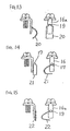
- FIGs. 12(A) to (D) An assembly procedure sequence of the prescribed embodiment is shown in Figs. 12(A) to (D).
- the washer-attached terminal screws 8, 8 are set to the housing main body 9 (Fig. 12(A)); then, a contact kit including the terminal fixtures 6, 6 and transmitter element 3 is attached thereto (Fig. 12(B)); thereafter, the coil springs 18, 18 are dropped down into specified spaces under natural conditions (Fig. 12(C)); lastly, the main body casing 10 is assembled (Fig. 12(D) ) completing the assembly procedure.
- Fig. 16(A) is its back side view whereas Fig. 16(B) is a side view thereof. Note in Fig. 16(B) that the lower part corresponds to the front side in an ordinary use situation whereas the upper part corresponds to the back side.
- Fig. 17 is a pictorial representation of a cross-section of a housing as taken along a plane passing through the center lines of two terminal screws 38, 38 at the contact section 32 discussed supra.
- a contact section 32 is coupled by elastic engagement pieces 42 of casing main body 40 in back of an operation section 31 to ensure that instructions from the operation section 31 are transferred to a transmitter element 33, which is rendered operative in response to an operation of the operation section 1 thereby causing movable contacts 34 to be ON and OFF with respect to fixed contacts 35 associated therewith.
- Each fixed contact 35 is provided at one end of a terminal fixture 36.
- a female screw 37 is formed at an emboss section of the terminal fixture 36 for allowing a washer-attached terminal screw 38 to be mated with the female screw 37 with a lead wire terminal being sandwiched between the surface of terminal fixture 36 and a washer 44.
- the foregoing respective parts are held by a housing main body 39.
- the transmitter element 33 changes in position to move forwardly (downward in the drawing) while allowing the contacts 34, 35 to turn off; when the operation section 31 is operated to turn on, the transmitter element 33 is displaced backwardly causing contacts 34, 35 to turn on.
- the axis directions ⁇ , ⁇ of terminal screws 38, 38 are slanted causing the screw head section to open.
- Such terminal screw axis inclination makes easier driver-tool operations of terminal screws in cases where a plurality of the contact section are to be coupled together while enabling the recovery force of the torsion coil spring to function efficiently as will be described later.
- Fig. 19 is a diagram showing a side view of the above embodiment at certain side opposite to that of Fig. 17 under the condition that the main body casing 40 is removed away; and, Fig. 20 depicts its elevational view.
- Fig. 21 is a partly enlarged view of a torsion coil spring and its associated nearby portion, and Fig. 22 illustrates a cross-section as taken along line B-B of Fig. 21.
- This partition wall is provided in a specified direction that subdivides the thickness direction of this terminal device into two portions.
- This partition wall has a surface 47 on one side whereat the torsion coil spring 46 is disposed, which surface is surrounded by a first barrier 48 extending in the forward/backward direction for partition of the transmitter element 39, and a second barrier 49 elongated in the right/left direction for partitioning the contacts 34, 35.
- a circular projection 50 is integrally formed near an intersection of these two barriers 48, 49 - i.e. at one corner of the surface 47 - thus allowing the coil section of torsion coil spring 46 to be attached to the projection 50.
- the first barrier 48 is formed with a stopper section at which the distal end of a fixed arm 51 of the torsion coil spring 46 rests whereas the second barrier 49 has a through-going hole allowing the washer guide section 45 to pass through it.
- a movable arm 52 of the torsion coil spring 46 is latched at its distal end to the tip of washer guide section 45.
- a stopper section is formed for slidably supporting the same. Note in Fig. 21 that a dash-and-dot line K is used to indicate the center line of a passage for permitting displacement of the washer guide section 45.
- the projection 50 is disposed at a position spaced apart by a predefined distance D from the passage K of this washer guide section.
- the terminal screw 38 is separated together with its washer 44 from the terminal fixture 36 due to presence of a recovery force of the torsion coil spring 46 thereby to define an opening as wide enough to permit insertion of a lead wire or the like between the distal end of terminal screw 38 and the terminal fixture 36.
- the the lead wire may be inserted from any one of two perpendicular directions: a direction W 3 shown in Figs. 16 and 17, or alternatively, a direction W 4 shown in Fig. 16.
- the washer guide section 46 is likewise displaced causing the torsion coil spring 46 to change in shape as shown in Fig. 23.
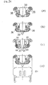
- Figs. 24(A) to (D) are diagrams for explanation of an assembly method of the above-mentioned comparative example.
- the washer-attached terminal screws 38, 38 are set to the housing main body 39 (Fig. 24(A)); then, a contact kit involving the terminal fixtures 36, 36 and transmitter element 39 is attached thereto (Fig. 24(B)).
- the torsion coil springs 46, 46 are put on the surface 47 under natural conditions (Fig. 24(C)); next, the torsion coil spring 46 is forced to slide on the surface 47 to come closer to the projection 50.
- the torsion coil spring 46 may be successfully set to the projection 50 as can be seen from Figs. 19 and 21.
- the main body casing 40 is assembled (Fig. 24(D)) completing the assembly procedure.
- the upper terminal screw 69A is in the recovered state defining an opening or gap between the surface of terminal fixture 66 and the distal end plane of terminal screw 69A for permitting insertion of a lead wire or the like.
- the lower terminal screw 69B is in the locked or clamped state with a lead wire terminal held therebetween.
- the two terminal screws 69A, 69B are disposed at selected locations exhibiting point-to-point symmetry in a manner such that all but the top portions of terminal screws are covered by the terminal-side housing 68 including the finger protect sections 70, 70, and that circular driver-insertion holes 70A, 70A permitting rotation of terminal screws are defined at selected portions corresponding to the terminal screw top portions of the finger protect sections 70, 70.
- Fig. 27 shows an enlarged back side view of a washer for support of a terminal screw and its nearby section
- Fig. 28 is a GHIJ cross-section of the structure of Fig. 27. Note here that the GH cross-section of Fig. 27 crosses at right angles with the CD cross-section of Fig. 26.
- a terminal-side housing 68 is coupled by rigid engagement in back of a main body-side housing 67 while causing two terminal fixtures 66, 66 to be electrically connected to a transformer 64 and also placed on the side of the main body-side housing.
- a screw hole 71 is defined at each terminal fixture 66 for being mated with a corresponding terminal screw 69.
- a washer 72 is located in back of the terminal screw 66.
- a terminal screw 69 is inserted rotatably but unreleasably into a substantially square washer section 72A of the washer 72.
- a washer guide section 73 of a substantially rectangular shape and spring pressing section 74 are integrally formed at the washer section 72A.
- the terminal-side housing 68A has a finger protect section 70 formed at the opposite side to the location of indicator section 61 for functioning as a stopper that may define the recovery position of the terminal screw 69.
- a washer guide groove 75, a cylindrical recovery compression coil spring containment space 76 and a guide bar 77 are integrally formed near the finger protect section 70 on the surface opposing the indicator section 61, wherein the washer guide groove 75 is for causing the washer guide section 73 to displace and slide in a direction parallel with the axis direction of the terminal screw 69, and wherein the guide bar 77 centrally penetrates through the spring containment space 76 and has its forward tip acting as a free end.
- the foregoing respective parts are coupled with a wall section on the side of the indicator section 61 of terminal-side housing 68.
- a latch section 79 is also integrally formed at one part of the front opening section (the position for intersection with terminal fixture 66) of the spring containment space 76 for permitting insertion of a coil spring 78 and yet preventing its release therefrom.
- the washer guide section 75, spring containment space 76 and guide bar 77 are parallel in axis direction to the terminal screw 69. Characteristically, the length of the washer guide section 73 is short so that it equals to that of the terminal screw 69 whereby it remains free from engagement with the terminal fixture 66.
- terminal screw 69 is unclamped in order to take out the lead wire or the like, when the terminal screw 69 goes out of the screw hole 71 of terminal fixture 66, the device is quickly recovered at its recovered state due to application of the recovery force of the coil spring 78.
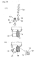
- Figs. 29(A) and (B) show an assembly process sequence of the above comparative example.
- the terminal screw 69 is provided at the washer section 72A of washer 72 in a way such that it remains rotatable but is prevented from releasing or dropping down from it.
- the coil spring 78 is provided allowing the guide bar 77 to be placed at the center of coil spring 78 in the spring containment space 76.
- the coil spring 78 is compressed causing it to reside at the latch section 79 of the spring containment space 76, whereby the terminal screw 69 comes at the recovery position as shown in Fig.
- the washer guide section 73 and washer guide groove 75 as used in this comparative example may be modified in various forms when reduction to practice. Several ones of such modifications are illustrated in Fig. 30. Note in Fig. 30 that while pictorial representation of the coil spring(s) is eliminated, the disposal location of such coil spring may also be fully selectable along with that of the washer guide section.
- a structure shown in Fig. 30(A) is arranged to provide a T-shaped washer guide section 73A at one side of a square washer 72.
- Shown in Fig. 30(B) is a structure which further employs L-shaped bent sections 73B at the both sides of the aforesaid T-shape.
- FIG. 30(C) is arranged by extending one side of the washer 72 into a rectangular shape with its extension part 73C being used as the washer guide section.
- a structure of Fig. 30(D) is provided with a washer guide section 73D of a hook shape at part of one side of the washer 72.
- FIG. 31 to 36 A further comparative example not being a part of the invention is shown in Figs. 31 to 36 which makes use of a torsion coil spring as its recovery spring for a transformer-associated terminal device similar to that shown in Figs. 25 to 30.
- Fig. 31 shows a back side view of an example incorporating the invention into the transformer-associated indicator lamp whereas Fig. 32 depicts an LMNO cross-section of the structure of Fig. 31.
- An indicator section 81 has an indication section on its front side.
- a transformer section 82 is coupled in back of the indicator section 81; in further back of it, a terminal section 83 is provided.
- the transformer section 82 includes a transformer 84 with its primary winding electrically interconnected to terminal fixtures 86, 86 on the back side, and a secondary winding electrically connected to plug-like terminals 85, 85, which are electrically coupled to a light source as built in the indicator section 81, such as an incandescent lamp (not shown) by way of example.
- the transformer 84 is wrapped by a main body-side housing 87, in back of which a terminal-side housing 88 is coupled by engagement therewith.
- This terminal-side housing 88 has finger-protect sections 90, 90 as integrally formed therewith for covering the head portions of terminal screws 89, 89 while functioning also as stoppers.
- the two terminal screws 89, 89 are disposed at selected locations offering point-to-point symmetry in a manner such that all but the top portions of terminal screws 89, 89 are covered by the terminal-side housing 88 including the finger protect sections 90, 90, and that round driver-insertion holes permitting rotation of terminal screws 89, 89 are defined at certain portions corresponding to the terminal screw top portions of the finger protect sections 90, 90.
- a washer 92 for supporting the terminal screw 89 is of a substantially square shape: It has one side at which a down-standing piece is formed to be bent at right angles toward the terminal fixture thus forming a washer guide section 93.
- This washer guide section 93 is displaceable and slidable in the axis direction of the terminal screw 89 along a washer guide groove 94 as formed in the terminal-side housing 88.
- the terminal-side housing 88 is formed with a recovery torsion coil spring containment space 95 which is adjacent to the washer guide groove 94 and is open at its back plane for allowing a torsion coil spring 96 to be held within this spring containment space 95.
- the torsion coil spring 96 is configured under free condition so that it has a coil section 96a and two arm sections 96b, 96c, wherein the tip of each arm section is bent orthogonally forming a stopper distal end section 96d, 96e.
- This torsion coil spring 96 exhibits point-symmetry and has no direction-dependency.
- a cut-away portion 97 is formed at certain location on a side surface as distant far from the torsion coil spring 96 of the washer guide section 93 thus allowing the movable arm section 96c of torsion coil spring 96 to rest here at its hook-shaped distal end section 96e.
- the spring containment space 95 may consist of a hold section of a semicylindrical shape for accepting and holding therein the coil section 96a of torsion coil spring 96, and an installation passage 99 having an opening on the housing back side for accommodation of the torsion coil spring 96 into the hold section 98.
- a stopper section 100 is formed at certain location on a side surface distant far from the washer guide groove 94 of holder section 98, causing the fixed arm section 96d of torsion coil spring 96 to rest thereon at its distal end section 96d to thereby eliminate any accidental release therefrom.
- the movable arm section 96c of torsion coil spring 96 may be displaced with a change in position of the washer guide section 93; the torsion coil spring 96 operates to continuously apply to the washer guide section 93 a specific force which pushes it backward.
- the position of the torsion coil spring 96 is in back of the location of the screw hole as provided at the terminal fixture 86. Accordingly, the stopper point with the torsion coil spring 96 as provided at the washer guide section 93 is near or around the washer 92 causing the washer guide section 93 to decrease in dimension in the forward/backward direction.
- the washer guide section is increased in size due to the fact that the torsion coil spring 114 is disposed along an extension line from the axis direction of the terminal screw 110 whereas the washer guide section 112 is supported so that it penetrates the terminal fixture 111 even in the state that the terminal screw 110 is placed at a position farthest from the terminal screws 111. Also importantly, the direction of a line connecting bending points of the washer 92 and washer guide section 93 is at right angles to the axis direction of torsion coil spring 96. For instance, in the prior art shown in Fig. 4, the two directions are in parallel with each other. These characteristics of the invention may greatly contribute to a reduction in depth dimension of the terminal device as a whole.
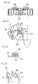
- FIG. 35 An assembly method of the torsion coil spring 96 is shown in Fig. 35.
- the washer guide section 93 which is formed at the washer 92 of terminal screw 89 is inserted into the washer guide groove 94 from the front side of the terminal-side housing 88 causing the head section of the terminal screw 89 to be brought into contact with the finger protect section 90.
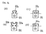
- the washer guide section 93 and washer guide groove 94 of the invention may be modified in a variety of ways when reduction to practice. Some of such modifications are illustrated in Fig. 36.
- a structure shown in Fig. 36(A) employs a T-shaped washer guide section 93A provided at one side of a square washer 92.
- Depicted in Fig. 36(B) is a structure which further employs L-shaped bent sections 93B at both sides of the aforesaid T-shape.
- a structure of Fig. 36(C) is configured by extending one side of the washer 92 into a rectangular shape with its extension part 93C used as the washer guide section.
- a structure of Fig. 36(D) comes with a hook-shaped washer guide section 93D at part of one side of the washer 92.
- Fig. 1 shows a push button switch which is one prior art of the present invention.
- Fig. 2 is a diagram showing in partial cross-section a side view of a transformer-attached indicator lamp which is another prior art of the invention.
- Fig. 3 is a partial cross-sectional view of the back side of the transformer-attached indication lamp of Fig. 2.
- Fig. 4 shows a terminal device as still another prior art of the invention.
- Fig. 5 depicts yet another prior art of the invention.
- Fig. 6 depicts a further prior art of the invention.
- Fig. 7 is a diagram showing a cross-sectional view, in a direction along an associative terminal screw, of a terminal device for a push button switch in accordance with one preferred embodiment of the invention.
- Fig. 8 is a diagram depicting a cross-section of the terminal device of Fig. 7 along a recovery spring thereof.
- Fig. 9 is a diagram showing an outer appearance of a housing of the terminal device of Fig. 7.
- Fig. 10 is a disassembly diagram of a housing main body 9 and main body casing 10 of the terminal device of Fig. 7.
- Fig. 11 is a diagram showing a recovery mechanism part of the terminal device of Fig. 7.
- Fig. 12 is a diagram showing the time-sequential assembly process steps of the terminal device of Fig. 7.
- Fig. 14 is a diagram showing a still another modified embodiment of the recovery spring of the invention.
- Fig. 15 is a diagram showing a yet another modified embodiment of the recovery spring of the invention.
- Fig. 16 illustrates outer appearance of a terminal device for use with a push button in accordance with an comparative example not being a part of the invention, wherein (A) is a back side view whereas (B) is a side view thereof.
- Fig. 17 is a diagram showing a cross-sectional view of the terminal device of Fig. 16.
- Fig. 18 is a disassembly diagram of a housing main body 39 and main body casing 40 of the terminal device of Fig. 16.
- Fig. 19 is a diagram showing a side view of the terminal device of Fig. 16 at the opposite side to that of Fig. 17 with the main body casing 40 removed away.
- Fig. 20 is an elevational view of the structure shown in Fig. 19.
- Fig. 21 is a diagram showing an enlarged view of the recovery spring of Fig. 19 along with its nearby section.
- Fig. 22 is a B-B cross-sectional view of the structure of Fig. 21.
- Fig. 23 is a diagram for explanation of an operation of a washer guide section and its associated recovery spring of the terminal device of Fig. 16.
- Fig. 24 is a diagram for explanation of assembly process of the terminal device of Fig. 16.
- Fig. 25 is a diagram showing in cross-section a transformer-associated indicator lamp in accordance with another comparative example not being a part of the invention.
- Fig. 26 is a back-surface diagram of the terminal device of Fig. 25.
- Fig. 27 is an enlarged back-surface diagram of a washer supporting a terminal screw of the terminal device of Fig. 25 along with the nearby section thereof.
- Fig. 28 is a GHIJ cross-sectional diagram of the structure of Fig. 27.
- Fig. 29 is a diagram for explanation of assembly process of the terminal device of Fig. 25.
- Fig. 30 is a diagram showing one modification of a washer guide section 37 and its associated washer guide groove 75 in the invention.
- Fig. 31 is a back-surface diagram of a transformer-associated indicator lamp in accordance with a still further comparative example not being a part of the invention.
- Fig. 32 is an LMNO cross-sectional diagram of the structure of Fig. 31.
- Fig. 33 depicts a back side view (A) and its side view (B) of a recovery spring adaptable for use in the terminal device of Fig. 31.
- Fig. 34 is a partly enlarged illustration of the recovery spring and its nearby section of the terminal device of Fig. 31.
- Fig. 35 is a diagram for explanation of one exemplary assembly method of the recovery spring in the terminal device of Fig. 31.
- Fig. 36 is a diagram showing a modification of the washer guide section and washer guide groove of this invention.
Landscapes
- Connections Arranged To Contact A Plurality Of Conductors (AREA)
- Connections By Means Of Piercing Elements, Nuts, Or Screws (AREA)
- Push-Button Switches (AREA)
Description
Claims (3)
- A terminal device having at one side of a washer (14) supporting a terminal screw (8), a washer guide section (16) being bent toward a terminal fixture (6) mated with the terminal screw (8), while extending in parallel with the axis of said terminal screw (8), wherein in the locked state of said terminal device, a recovery spring (18) is compressed by said washer guide section (16),
characterized in that
said recovery spring (18) is provided between a housing (9) and an intermediate portion of said washer guide section (16) at the opposite side to said terminal screw (8) which side turning away from the terminal fixture (6) and the washer (14). - The terminal device according to claim 1, wherein said recovery spring (18) is a compression coil spring having a housing-side receptor section engageable with the housing main body (9).
- The terminal device according to claim 1, wherein a finger protect section (13) is formed to be integral with the housing (9) supporting said terminal fixture for also attaining a stopper function during detachment of said terminal screw (8).
Applications Claiming Priority (7)
| Application Number | Priority Date | Filing Date | Title |
|---|---|---|---|
| JP4298196 | 1996-02-29 | ||
| JP08042982A JP3110672B2 (en) | 1996-02-29 | 1996-02-29 | Terminal device |
| JP8042981A JP3056066B2 (en) | 1996-02-29 | 1996-02-29 | Terminal device |
| JP42982/96 | 1996-02-29 | ||
| JP42981/96 | 1996-02-29 | ||
| JP4298296 | 1996-02-29 | ||
| PCT/JP1997/000634 WO1997032361A1 (en) | 1996-02-29 | 1997-02-28 | Terminal device |
Publications (3)
| Publication Number | Publication Date |
|---|---|
| EP0825679A1 EP0825679A1 (en) | 1998-02-25 |
| EP0825679A4 EP0825679A4 (en) | 2000-02-09 |
| EP0825679B1 true EP0825679B1 (en) | 2003-05-14 |
Family
ID=26382718
Family Applications (1)
| Application Number | Title | Priority Date | Filing Date |
|---|---|---|---|
| EP97905432A Expired - Lifetime EP0825679B1 (en) | 1996-02-29 | 1997-02-28 | Terminal device |
Country Status (7)
| Country | Link |
|---|---|
| US (1) | US6193566B1 (en) |
| EP (1) | EP0825679B1 (en) |
| KR (1) | KR100473828B1 (en) |
| CN (1) | CN1088921C (en) |
| DE (1) | DE69721912T2 (en) |
| TW (1) | TW359911B (en) |
| WO (1) | WO1997032361A1 (en) |
Families Citing this family (11)
| Publication number | Priority date | Publication date | Assignee | Title |
|---|---|---|---|---|
| DE10339670B4 (en) * | 2003-08-28 | 2006-02-16 | Siemens Ag | Clamping device and thus equipped switching device for conductor connection by means of ring cable lug |
| DE202004002779U1 (en) * | 2004-02-21 | 2005-06-30 | Wieland Electric Gmbh | Terminal block e.g. for closed cable lugs, has spring-loaded flange positioned in threaded channel |
| US20070117471A1 (en) * | 2005-11-19 | 2007-05-24 | Liebert Corporation | Battery connection systems and methods for use thereof |
| KR100890167B1 (en) * | 2007-05-31 | 2009-03-25 | (주)티에이치엔 | Connector Chip Guide |
| CN102394424B (en) * | 2011-06-22 | 2013-02-13 | 上海航天科工电器研究院有限公司 | Electrical connector of self-return type sliding cover structure |
| US9006946B2 (en) * | 2012-06-29 | 2015-04-14 | Samsung Electro-Mechanics Co., Ltd. | Motor structure and flat type vibration motor structure using the same |
| CN107504894B (en) * | 2017-09-07 | 2024-04-09 | 武汉优泰电子技术有限公司 | Binding post for strain gauge |
| BE1025978B1 (en) * | 2018-02-05 | 2019-09-03 | Phoenix Feinbau Gmbh & Co Kg | Method for producing a threaded hole in a busbar piece of a terminal |
| KR102552796B1 (en) * | 2018-09-28 | 2023-07-06 | 아이뎃쿠 가부시키가이샤 | enable switch |
| JP7232073B2 (en) * | 2019-02-18 | 2023-03-02 | 日本航空電子工業株式会社 | Connection method, connection structure and connection terminal |
| US10498053B1 (en) * | 2019-02-19 | 2019-12-03 | Stephen Sawzin | Electrical wiring junction box |
Family Cites Families (10)
| Publication number | Priority date | Publication date | Assignee | Title |
|---|---|---|---|---|
| JPS59110980U (en) * | 1983-01-15 | 1984-07-26 | 吉田電機工業株式会社 | Terminal block |
| JPS6163759A (en) | 1984-09-05 | 1986-04-01 | 東レ株式会社 | Production of higly interlaced felt |
| JPH044366Y2 (en) * | 1986-04-15 | 1992-02-07 | ||
| JPS63105236A (en) | 1986-10-21 | 1988-05-10 | Mazda Motor Corp | Lubricating oil supplying device for rotary piston engine |
| JPH01143248A (en) * | 1987-11-30 | 1989-06-05 | Nec Corp | Semiconductor integrated circuit device |
| JPH0526906Y2 (en) * | 1988-03-23 | 1993-07-08 | ||
| JPH0244663A (en) * | 1988-08-04 | 1990-02-14 | Fuji Denki Kogyo Kk | Terminal base device |
| JP2725519B2 (en) * | 1991-10-01 | 1998-03-11 | 三菱電機株式会社 | Terminal block |
| JPH06195595A (en) | 1992-12-25 | 1994-07-15 | Mazda Motor Corp | Display device for vehicle |
| JPH07105999A (en) * | 1993-10-01 | 1995-04-21 | Toyo Giken Kk | Terminal connecting device |
-
1997
- 1997-02-27 TW TW086102401A patent/TW359911B/en not_active IP Right Cessation
- 1997-02-28 DE DE69721912T patent/DE69721912T2/en not_active Expired - Lifetime
- 1997-02-28 CN CN97190226A patent/CN1088921C/en not_active Expired - Lifetime
- 1997-02-28 EP EP97905432A patent/EP0825679B1/en not_active Expired - Lifetime
- 1997-02-28 KR KR1019970707541A patent/KR100473828B1/en not_active Expired - Lifetime
- 1997-02-28 US US08/945,709 patent/US6193566B1/en not_active Expired - Lifetime
- 1997-02-28 WO PCT/JP1997/000634 patent/WO1997032361A1/en not_active Ceased
Also Published As
| Publication number | Publication date |
|---|---|
| TW359911B (en) | 1999-06-01 |
| CN1183175A (en) | 1998-05-27 |
| KR19990008017A (en) | 1999-01-25 |
| DE69721912T2 (en) | 2004-03-11 |
| EP0825679A1 (en) | 1998-02-25 |
| DE69721912D1 (en) | 2003-06-18 |
| EP0825679A4 (en) | 2000-02-09 |
| CN1088921C (en) | 2002-08-07 |
| KR100473828B1 (en) | 2005-08-17 |
| US6193566B1 (en) | 2001-02-27 |
| WO1997032361A1 (en) | 1997-09-04 |
Similar Documents
| Publication | Publication Date | Title |
|---|---|---|
| US6193566B1 (en) | Terminal device | |
| US7909664B2 (en) | Wire termination apparatus and method | |
| US20050098419A1 (en) | Lever fitting-type power supply circuit breaker | |
| EP1077456A2 (en) | Breaker device | |
| WO2012063528A1 (en) | Connector and switch | |
| JP3161351B2 (en) | Auto-lock continuity inspection unit | |
| EP0535507A2 (en) | A terminal connecting device | |
| KR101361879B1 (en) | Slide switch | |
| CN106953214B (en) | Connector plug with two groups of different current pin groups | |
| JP3605923B2 (en) | Wire connection terminal device, outlet provided with wire connection terminal device, switch provided with wire connection terminal device, connector provided with wire connection terminal device, terminal block provided with wire connection terminal device, and joint provided with wire connection terminal device box | |
| EP1326261B1 (en) | Grip type switch device and controller for industrial machinery using the switch device | |
| EP1605559B1 (en) | Socket for electric component | |
| GB2325796A (en) | Clamping in ultrasonic cable connection | |
| MY117442A (en) | Socket for electrical parts with guide wall section to keep lever members from coming off | |
| KR19990013992A (en) | Electrical connector assembly with means for simultaneously mating plugs and receptacle connectors | |
| KR100290210B1 (en) | Modular jack | |
| KR200224291Y1 (en) | Multi way switch | |
| CN100429827C (en) | Cable connectors and connector terminal blocks for electrical contact with cables | |
| EP1263008B1 (en) | Switch device | |
| CN218415198U (en) | Door contact switch and socket thereof | |
| JP3110666B2 (en) | Terminal device | |
| CN212848144U (en) | Gate control switch | |
| JP2003086285A (en) | Power supply plug | |
| CN218415196U (en) | Door contact switch convenient to disconnect and socket thereof | |
| JPH0548390Y2 (en) |
Legal Events
| Date | Code | Title | Description |
|---|---|---|---|
| PUAI | Public reference made under article 153(3) epc to a published international application that has entered the european phase |
Free format text: ORIGINAL CODE: 0009012 |
|
| 17P | Request for examination filed |
Effective date: 19971203 |
|
| AK | Designated contracting states |
Kind code of ref document: A1 Designated state(s): CH DE DK FR GB LI SE |
|
| A4 | Supplementary search report drawn up and despatched |
Effective date: 19991223 |
|
| AK | Designated contracting states |
Kind code of ref document: A4 Designated state(s): CH DE DK FR GB LI SE |
|
| RIC1 | Information provided on ipc code assigned before grant |
Free format text: 7H 01R 4/38 A, 7H 01R 9/22 B, 7H 01R 4/30 B |
|
| 17Q | First examination report despatched |
Effective date: 20001130 |
|
| GRAG | Despatch of communication of intention to grant |
Free format text: ORIGINAL CODE: EPIDOS AGRA |
|
| GRAG | Despatch of communication of intention to grant |
Free format text: ORIGINAL CODE: EPIDOS AGRA |
|
| GRAH | Despatch of communication of intention to grant a patent |
Free format text: ORIGINAL CODE: EPIDOS IGRA |
|
| GRAH | Despatch of communication of intention to grant a patent |
Free format text: ORIGINAL CODE: EPIDOS IGRA |
|
| GRAA | (expected) grant |
Free format text: ORIGINAL CODE: 0009210 |
|
| AK | Designated contracting states |
Designated state(s): CH DE DK FR GB LI SE |
|
| PG25 | Lapsed in a contracting state [announced via postgrant information from national office to epo] |
Ref country code: LI Free format text: LAPSE BECAUSE OF FAILURE TO SUBMIT A TRANSLATION OF THE DESCRIPTION OR TO PAY THE FEE WITHIN THE PRESCRIBED TIME-LIMIT Effective date: 20030514 Ref country code: CH Free format text: LAPSE BECAUSE OF FAILURE TO SUBMIT A TRANSLATION OF THE DESCRIPTION OR TO PAY THE FEE WITHIN THE PRESCRIBED TIME-LIMIT Effective date: 20030514 |
|
| REG | Reference to a national code |
Ref country code: GB Ref legal event code: FG4D |
|
| REG | Reference to a national code |
Ref country code: CH Ref legal event code: EP |
|
| REF | Corresponds to: |
Ref document number: 69721912 Country of ref document: DE Date of ref document: 20030618 Kind code of ref document: P |
|
| PG25 | Lapsed in a contracting state [announced via postgrant information from national office to epo] |
Ref country code: SE Free format text: LAPSE BECAUSE OF FAILURE TO SUBMIT A TRANSLATION OF THE DESCRIPTION OR TO PAY THE FEE WITHIN THE PRESCRIBED TIME-LIMIT Effective date: 20030814 Ref country code: DK Free format text: LAPSE BECAUSE OF FAILURE TO SUBMIT A TRANSLATION OF THE DESCRIPTION OR TO PAY THE FEE WITHIN THE PRESCRIBED TIME-LIMIT Effective date: 20030814 |
|
| REG | Reference to a national code |
Ref country code: CH Ref legal event code: PL |
|
| ET | Fr: translation filed | ||
| PLBE | No opposition filed within time limit |
Free format text: ORIGINAL CODE: 0009261 |
|
| STAA | Information on the status of an ep patent application or granted ep patent |
Free format text: STATUS: NO OPPOSITION FILED WITHIN TIME LIMIT |
|
| 26N | No opposition filed |
Effective date: 20040217 |
|
| REG | Reference to a national code |
Ref country code: FR Ref legal event code: PLFP Year of fee payment: 20 |
|
| PGFP | Annual fee paid to national office [announced via postgrant information from national office to epo] |
Ref country code: DE Payment date: 20160226 Year of fee payment: 20 |
|
| PGFP | Annual fee paid to national office [announced via postgrant information from national office to epo] |
Ref country code: FR Payment date: 20160222 Year of fee payment: 20 Ref country code: GB Payment date: 20160222 Year of fee payment: 20 |
|
| REG | Reference to a national code |
Ref country code: DE Ref legal event code: R071 Ref document number: 69721912 Country of ref document: DE |
|
| REG | Reference to a national code |
Ref country code: GB Ref legal event code: PE20 Expiry date: 20170227 |
|
| PG25 | Lapsed in a contracting state [announced via postgrant information from national office to epo] |
Ref country code: GB Free format text: LAPSE BECAUSE OF EXPIRATION OF PROTECTION Effective date: 20170227 |