EP0825560A2 - Verfahren zur Herstellung von Animationen - Google Patents
Verfahren zur Herstellung von Animationen Download PDFInfo
- Publication number
- EP0825560A2 EP0825560A2 EP97114351A EP97114351A EP0825560A2 EP 0825560 A2 EP0825560 A2 EP 0825560A2 EP 97114351 A EP97114351 A EP 97114351A EP 97114351 A EP97114351 A EP 97114351A EP 0825560 A2 EP0825560 A2 EP 0825560A2
- Authority
- EP
- European Patent Office
- Prior art keywords
- motion
- arm
- rigid
- modeling
- models
- Prior art date
- Legal status (The legal status is an assumption and is not a legal conclusion. Google has not performed a legal analysis and makes no representation as to the accuracy of the status listed.)
- Granted
Links
Images


Classifications
-
- G—PHYSICS
- G06—COMPUTING OR CALCULATING; COUNTING
- G06T—IMAGE DATA PROCESSING OR GENERATION, IN GENERAL
- G06T13/00—Animation
- G06T13/20—3D [Three Dimensional] animation
- G06T13/40—3D [Three Dimensional] animation of characters, e.g. humans, animals or virtual beings
Definitions
- the present invention relates to a method for generating animations of a human figure modeled by a multi-articulated structure in computer graphics (CG) and, more particularly, to a method for generating animations of shoulder rotation and arm swing of a human figure modeled by a multi-articulate d structure constructed by rigid bars or sticks connected or joined by joints, a recording medium having recorded thereon the method and an animation generating apparatus using the method.
- CG computer graphics
- the method for generating animations of various parts of the human body by the use of such parameters utilizes (1) an interpolation scheme that employs linear or elementary functions, (2) a scheme that formulates an equation of motion and performs numerical calculations to satisfy initial and final conditions, or (3) a scheme that uses motion data obtained by extracting feature parameters of joint positions in the human body from an image taken by a video camera or measuring positional changes of the human body by a magnetic or electric sensor.
- An object of the present invention is to provide an animation generating method according to which, in the generation of an animation of a human figure modeled by a multi-articulated structure using rigid sticks joined by joints, parameters contributing to the motions of respective rigid sticks are easy to identify and individually controllable and motion generating schemes for the respective parameters can freely be selected or combined.
- Another object of the present invention is to provide an animation generating method using the above method and a recording medium with the method recorded thereon.
- the animation generating method models the human body including shoulders and arms by a multi-articulated structure made up of plural rigid sticks connected by joints and generates the modeled human figure motions. This method comprises the following steps:
- the animation generating apparatus models the human body including shoulders and arms by a multi-articulated structure made up of plural rigid sticks connected by joints and generates human figure animations.
- This apparatus comprises:
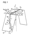
- Fig. 1 schematically illustrates a multi-articulated structure and motions of its respective parts, for explaining the principles of the present invention.
- the human body is modeled by a multi-articulated structure including both shoulders and both arms formed by linking rigid sticks with joints, the arms each linked to one of the shoulder joints are allowed to rotate in a constraint plane passing through the link, and the position of the arm is defined by its angle to a reference line in the constraint plane.
- a parameter that defines the position of the arm is only an angle, and since the angle directly represents the angular position of the arm in the animation, motions of respective parts of the multi- articulated structure can easily be set in the production of the animation and angular position control is simple.
- a rigid stick 11 of a length 2W joining left and right shoulder joints 13 L nd 13 R is a modeled version of both shoulders of the human body and that the center O of the rigid stick 11 is set at a reference position (x 0 ,y 0 ,z 0 ) in a coordinate system (x,y,z).
- the normal of a circle 14 of rotation of the rigid stick 11 on the y axis (a vertical axis) passing through the center O of the rigid stick 11 vertically thereto represents the axial direction of the human body (the direction of the backbone).
- the circle 14 sits in an x-z plane, but as will be described later on, the plane of the circle 14 need not always to cross the y axis at right angles thereto.
- the right shoulder joint 13 R has rotatably connected thereto one end of the right upper arm 12 1 modeled by a rigid stick, to the other end of which is rotatably connected the right lower arm 12 2 similarly modeled by a rigid stick.
- the coordinates (x s ,y s ,z s ) of one end of the rigid stick 11 i.e.
- the shoulder joint 13 R in the 3D space are unequivocally determined by the following equation, based on an angle ⁇ between the projection of the rigid stick 11 to the x-z plane and the z axis and the shoulder width 2W.
- x s x 0 +Wsin ⁇
- y s y 0
- z s z 0 +Wcos ⁇
- the motion of the upper arm 12 1 of a length L 1 is constrained in a plane 15 containing a tangent 15a to the circle 14 at the upper end of the upper arm 12 1 , that is, at the shoulder joint 13 R .
- This plane will hereinafter referred to as a constraint plane.
- the upper arm 12 1 is rotatable about the shoulder joint 13 R in the constraint plane 15.
- the angular position of the upper arm 12 1 is defined by an angle ⁇ 1 , between the upper arm 121 and a reference line 15b that is a straight line along which a plane containing the rigid stick 11 and the y axis crosses the constraint plane 15.
- An angle ⁇ that the constraint plane 15 forms with the y axis represents a tilt angle of the upper arm 121 from the body and an angle ⁇ 1 of the upper arm 12 1 to the reference line 15b the angular position of a swing of the upper arm 12 1 from the body in the front-to-back direction. Similar angular positions of the right arm are also defined though not shown in Fig. 1.
- the motion of the lower arm 12 2 of a length L 2 connected to the lower end of the upper arm 12 1 (that is, to the elbow joint 16) is also constrained in the same constraint plane 15 as that of the upper arm 121 and its angular position is defined by an angle ⁇ 2 that the lower arm 12 2 forms with the upper am 12 1 .
- the parameter ⁇ 2 representative of the angular position of the lower arm 12 2 is also a parameter that directly indicates the attitude of the lower arm 12 2 of the human figure model.
- the prior art uses the coordinates (x,y,z) to represent the positions of feature points of a human figure animation (for example, an eye, a nose, tiptoe, an elbow, etc.) and generates an animation by expressing their motions using a linear interpolation or equation of motion, but in the case of using the coordinates (x,y,z) as parameters, it is no easy task for an observer to comprehend or grasp the attitude of the 3D animation. Also in the case of using cylindrical or polar coordinates, the angle parameters are not easy to grasp because the parameter representation does not match the actual human instinctive control. That is, since it is hard to learn which motion each parameter contributes to, it is no easy task to instinctively determine, for example, movement limits of respective parts of the human figure for generating an animation.
- the parameters ⁇ , ⁇ 1 and ⁇ 2 which define the arm 12 to which the present invention is applied, are parameters that enable the observer to directly understand the attitude of the human figure model and it is clear the motion to which each parameter contributes; therefore, these parameters are easy to use for governing the generation of human figure animations.
- the present invention has its feature in that motions of human arms are represented by changes in the arm positions defined by angle parameters in the constraint plane as referred to above.
- the position of the arm of the human figure is defined by the angle parameters in the constraint plane and the arm motion or swing is expressed using temporal variations of the angle parameters as described below.
- the modeling of the arm motion through utilization of the angle parameters can be done, for example, by (1) interpolating between two boundary conditions, (2) using an equation of motion that satisfies two boundary conditions, and (3) using measured data.
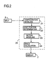
- Fig. 2 illustrates in block form the configuration of the multi-articulated structure animation generating apparatus according to the present invention, indicated generally by 20.
- the animation generating apparatus 20 comprises a configuration modeling part 21, a joint position determination part 22, a motion modeling part 23 and an angle calculation part 24.
- the configuration modeling part 21 is connected to an input part 6 that inputs information necessary for representing motions of the arm 12.
- the angle calculation part 24 outputs its calculated angular position of each rigid stick and provides it to a display part 7, which projects a 3D multi-articulated structure constructed by rigid sticks onto a 2D plane, thereby displaying an animation of the projected model.
- any of the above-mentioned methods can be used for modeling of the arm motion.
- the information necessary for the generation of the animation of the arm 12, for example, the coordinates (x s ,y s ,z s ) of the shoulder, the length L 1 of the upper arm 12 1 , the length L 2 of the lower arm 12 2 , initial angular positions ⁇ 1 and ⁇ 2 of the upper and lower arms and initial angular velocities at the initial angular positions, are input into the configuration modeling part 21.
- the mass of each of the upper and lower arms is also input.
- the configuration modeling part 21 models the arm 12 by approximating the arm structure with a physical pendulum formed as a rigid body, determines various physical quantities (the lengths, mass, centroids, maximum expansion angle, maximum bend angle and moment of inertia of the upper and lower arms, and outputs these arm models and its determined physical quantities.
- the joint position determination part 22 calculates the position of the shoulder joint 13 R that serves as the fulcrum of the rigid physical pendulum of the configuration modeling part 21.
- the position of the shoulder joint can be calculated by any methods as long as they regard it as a point in a 3D space and compute its coordinate value and velocity and acceleration.
- the motion modeling part 23 Based on the joint position determined by the joint position determination part 22, the motion modeling part 23 creates, following the designated modeling scheme, a motion model by generating an interpolation formula or equation of motion representing the arm-motion state through the use of the configuration model and physical quantities output from the configuration modeling part 21.
- the arm angle calculating part 24 calculates the angle representative of the configuration of the arm at a certain time t based on the equation of the motion model determined by the motion modeling part 23. In this instance, however, the angular position may be computed using plural motion models as described later on.
- Fig. 1 shows a configuration model in which the rigid stick 11 between the both shoulder joints is rotatable on the y axis within a predetermined angular range and the coordinate positions (x s ,y s ,z s ) of each shoulder joint is defined by the angle ⁇ of the shoulder about the y axis and the half shoulder width W
- the rigid stick 11 between the shoulder joints may be made rotatable on the x axis as well over a predetermined angular range with a view to creating a more realistic representation of the motion of the human figure model.
- Fig. 3 shows a configuration model in such an instance.
- the rigid stick 11 is shown to have turned an angle ⁇ about the y axis and an angle ⁇ about the x axis.
- the coordinates (x s ,y s ,z s ) of the shoulder joint is defined by the following equations using the angles ⁇ and ⁇ and the half shoulder width W.
- the rigid stick 11 between the both shoulder joints is turned on the vertical coordinate axis y, centrifugal force is exerted on the left and right arms 12 outwardly thereof.
- the angle r of the constraint plane 15 to the vertical coordinate axis ⁇ may be changed according to the centrifugal force.
- the motions of the arms 12 1 and 12 2 are defined by the angular positions ⁇ 1 and ⁇ 2 in the constraint plane 15 with respect to such given shoulder joint coordinates (x s ,y s ,z s ).
- the upper and lower arms 12 1 and 12 2 are shown to be movable in the same constraint plane 15, but in order to represent the motion of the arm model more faithfully to the actual arm motion, it is possible to divide the constraint plane 15, by a straight line passing through the elbow joint, into two independent constraint planes 15 1 and 15 2 for the upper and lower arms 12 1 and 12 2 , respectively.
- the constraint plane 152 containing the lower arm 12 2 is made rotatable over a predetermined range of angles about the upper arm 12 1 .
- the angular position of the lower arm 12 2 in the constraint plane 15 2 can be defined by the angles ⁇ 2 and ⁇ ; hence, once the coordinates (x E ,y E ,z E ) of the elbow joint 16 are defined, the position of the lower arm 12 2 can also easily be defined using these parameters.
- the arm angle calculation part 24 represents motions of respective parts based on one motion modeling scheme selected by the motion modeling part 23, the interpolation method has a defect that the motions becomes uniform and monotonous in the case of generating animations that do not primarily aim at motions accompanying the human walking, such as the arm motion or the like.
- the number of degrees of freedom increases according to the model building method, resulting in an increase in the computational complexity.
- the method for generating animations from image data of the human body in motion by a video camera or position detected data by a magnetic sensor is difficult of application to various motion scenes, it is necessary to acquire a wide variety of motion data.
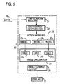
- Fig. 5 there is illustrated in block form an embodiment of the invention that overcomes such defects.
- This embodiment is identical in basic configuration with the Fig. 2 embodiment but differs from the latter in that the motion modeling part 23 is provided with plural (three in this example) kinds of modeling section 23a, 23b and 23c for modeling the motion state of the arm 12 by different methods. Another point of difference is that the arm angle calculation part 24 has calculation sections 24a, 24b and 24c respectively corresponding to the modeling sections 23a, 23b and 23c of the motion modeling part 23. Additionally, this embodiment has an angle combine/output part 26 that performs weighted combining of calculated angles. This embodiment will be described below.
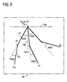
- the configuration modeling part 21 is supplied with input data from the input part 6, such as sizes, mass, shapes and boundary conditions (movable ranges of respective parts of a multi-articulated model of the human body, and uses the data to dispose respective parts of a structure formed by rigid sticks linked by joints, an arm model in this case. While in Fig. 4 the angles ⁇ 1 and ⁇ 2 are chosen so that the counterclockwise direction about the rigid stick 11 is positive, any coordinate system can be used as long as the orientation or configuration of the arm 12 can be represented unequivocally.
- the point position determination part 22 computes the positions of the shoulder joints 13 R and 13 L .
- the model of the shoulder is not limited specifically to that shown in Fig. 3 or 4 but may be others as long as the coordinates (x s ,y s ,z s ) of the should joint can be calculated.
- the motion modeling part 23 models the motion state of the arm model in the system of Fig. 4 by three different methods in this example. That is, based on the arm model and physical quantities determined in the configuration modeling part 21, the motion modeling part 23 determines modeling by equations of motion or modeling by equations of interpolation and outputs the models.
- the motions between the states q 0 , q 1 and q 2 are assumed to be linear motions, that is, the motion from the state q(t 0 ) to q(t 1 ) and from q(t 1 ) to q(t 2 ) are regarded as constant-speed motion states, and an equation of the motion state, which represents the angular position and/or angular velocity at given time t, is formulated using the linear interpolation method.
- the motion states between the states q 0 , q 1 and q 3 are assumed to be states of motion at a velocity approximated by a sine curve, for instance, and an equation of the motion state, which represents the angular position and/or angular velocity at given time 1, is formulated using the sine interpolation method.
- these states q 0 , q 1 and q 2 are assumed to be motion states that obey laws of physics, and they are defined as motions that result from the aforementioned Lagrange's equation of motion (6), where q is generalized coordinates ( ⁇ 1 , ⁇ 2 ) of this system and Fq a generalized force concerning q.
- the generalized force may be any force as long as the system can represent the states q 0 , q 1 and q 2 .
- angles ⁇ a 1 (t) and ⁇ a 2 (t) of the arm 12 at time t between t 0 and t 2 are calculated based on the motion state determined by the motion modeling section 23a.
- angles ⁇ b 1(t) and ⁇ b 2 (t) or ⁇ b 1 (t k ) and ⁇ b 2 (t k ) of the arm 12 are calculated based on the motion state determined by the motion modeling section 23b.
- angles ⁇ c 1 (t) and ⁇ c 2 (t) or ⁇ c 1 (t k ) and ⁇ c 2 (t k ) of the arm 12 are calculated based on the motion state determined by the motion modeling section 23c.
- motions of the arm 12 can efficiently be calculated as motions accompanying those of the rigid stick 11 between the both shoulders. Further, by combining or overlapping calculation results of plural motion states, it is possible to generate, for example, linear or dynamic motions alone, and by arbitrarily combining these motions, various other motion states can also be generated.
- this embodiment employs plural (three) sets of motion modeling select parts 27 and arm angle calculation parts 24 to prepare plural sets of different combinations of motion modeling schemes for each of the rigid sticks that model the arm, and as required, results of arm angle calculations by different set of such motion modeling schemes are subjected to weighted combining in the combine/output part 26.
- the configuration modeling part 21 determines the configuration of the arm as shown in Fig. 4, for instance. That is, the parameters that are designated in this case are the angle of rotation ⁇ of the shoulder about the axis in the forward direction (indicating rocking of the shoulder), the angle of rotation ⁇ of the shoulder about the axis in the vertical direction, the angle of rotation ⁇ of the constraint plane 15 1 containing the upper arm from the vertical plane (indicating the angle between the upper am and the side of the human figure under the armpit), the angle ⁇ 1 of the upper arm 12 1 in the constraint plane 15 1 , the angle of rotation ⁇ of the constraint plane 15 2 containing the lower arm 12 2 about the upper arm 12 1 and the angle ⁇ 2 of the lower arm 12 2 in the constraint plane 15 2 , and the reference position O is set at the center of the shoulder in Fig. 4, for instance.
- the joint position determination part 22 determines the position of the point O designated to be the origin in Fig. 4.
- the configuration modeling part 21 designates the coordinates (x 0 ,y 0 ,z 0 ) of the origin O to be at another point
- the joint position determination part 22 determines the that position. For example, when the point O is derivable from the motion of another part of the body, a certain point of that part is connected to the origin O.
- the motion modeling part 23 determines procedures of plural motion modeling schemes to be used. While this embodiment employs three kinds of motion modeling schemes, any other schemes may be added.
- the motion modeling section 23 utilizes dynamics.
- the afore-mentioned Lagrange's equation of motion (6) for this coordinate system is formulated by a well-known scheme of dynamics.
- the generalized coordinates q represent ⁇ , ⁇ , ⁇ R , ⁇ L , ⁇ R 1 , ⁇ L 1 , ⁇ R 2 , ⁇ L 2 , ⁇ R and ⁇ L
- the generalized force Fq is a torque corresponding to the individual coordinates, the suffixes R and L indicating the right and the left side, respectively.
- the motion modeling section 23b determines the parameter value at each point in time by the linear interpolation scheme. For example, where the values q 0 and q 1 of a certain motion state parameter q at initial and final points in time t 0 and t 1 of the motion are already determined, the value at an arbitrary time t (where t 0 ⁇ t ⁇ t 1 ) between the initial and final points in time is determined by linear interpolation. The same goes for the case where a value q m at time t m (where t 0 ⁇ t m ⁇ t 1 ) is already determined at initial time t 0 . It is no problem how many such values exist at points between the initial and final ones. Further, the parameters may also take the same value from initial time to to final one t 1 .
- the motion modeling section 23c determines the parameter value at each time by such a nonlinear interpolation as a sine function interpolation.
- the value of the parameter q at each time t is determined by such a combination of second- and third-order equations and an elementary that the parameter takes the already value at that time.
- the motion model select part 27 determined the motion state of the arm for which a calculation is actually conducted. For instance:
- the arm angle calculation part 24 performs actual angle calculations in the calculating sections 24a, 24b and 24c following the parameter calculating methods determined as described above. In this instance, it is also possible, with a view to providing increased efficiency for the calculation procedure, to conduct calculations at each time in the following order:
- the results calculated in the arm angle calculation part 24 may be used intact as output values, but other combinations of parameter calculating methods can be used.
- Fig. 7 there are provided pairs of motion modeling select sections and angle calculation sections 27', 24' and 27'', 24'' similar to the pair of motion modeling part 27 and angle calculation part 24 so that a combination of motion models to be applied to each rigid stick, different from the combination of motion models selected by the motion model select part 27, is selected and that arm angles are calculated based on the newly selected combination of motion models.
- the results of angular position calculations by the arm angle position calculating parts 24, 24' and 24'' for the rigid sticks respectively corresponding thereto are suitably weighted and combined in the combine/output part 26, from which the combined output is fed to the display part 7. In this case, the angle or angular velocity values at each point in time may also be combined.
- This embodiment is advantageous in that the computing time can be reduced as compared in the case of computing all parameters through utilization of dynamics in Fig. 4, for example, and that the value of a particular parameter can be varied arbitrarily or held constant.
- the animation generating methods of the present invention described previously with reference to Figs. 2, 5 and 8 are each prestored as animation generating sequences in a memory or similar recording medium and the animation is generated by a computer or DSP following the generating sequences read out of the recording medium.
- motions of respective rigid sticks connected by joints to form a multi-articulated structure are represented by parameters in a constraint plane for easier recognition of their contribution to the motions
- animations can efficiently be generated without any particular skill.
- the joint is a model approximated by a physical pendulum and the joint motion is represented by an equation of motion formulated for the model--this permits more realistic calculation of motions of the arm joint or the like.
- animations can efficiently be created and the individual parameters can be controlled with ease.
- angles or angular velocities formed by plural motion states are combined, a variety of motion states can be represented.
Landscapes
- Physics & Mathematics (AREA)
- General Physics & Mathematics (AREA)
- Engineering & Computer Science (AREA)
- Theoretical Computer Science (AREA)
- Processing Or Creating Images (AREA)
Applications Claiming Priority (3)
| Application Number | Priority Date | Filing Date | Title |
|---|---|---|---|
| JP21997296 | 1996-08-21 | ||
| JP21997296 | 1996-08-21 | ||
| JP219972/96 | 1996-08-21 |
Publications (3)
| Publication Number | Publication Date |
|---|---|
| EP0825560A2 true EP0825560A2 (de) | 1998-02-25 |
| EP0825560A3 EP0825560A3 (de) | 1999-01-27 |
| EP0825560B1 EP0825560B1 (de) | 2004-03-03 |
Family
ID=16743923
Family Applications (1)
| Application Number | Title | Priority Date | Filing Date |
|---|---|---|---|
| EP97114351A Expired - Lifetime EP0825560B1 (de) | 1996-08-21 | 1997-08-20 | Verfahren zur Herstellung von Animationen |
Country Status (4)
| Country | Link |
|---|---|
| US (1) | US6104412A (de) |
| EP (1) | EP0825560B1 (de) |
| CA (1) | CA2213884C (de) |
| DE (1) | DE69727866T2 (de) |
Cited By (4)
| Publication number | Priority date | Publication date | Assignee | Title |
|---|---|---|---|---|
| GB2372420A (en) * | 2000-12-11 | 2002-08-21 | 20 20 Speech Ltd | Virtual presenter |
| GB2391146A (en) * | 2002-07-17 | 2004-01-28 | Kaydara Inc | Generating animation data with constrained parameters |
| EP1505546A2 (de) | 2003-08-06 | 2005-02-09 | Kabushiki Kaisha Square Enix (also trading as Square Enix Co., Ltd.) | Verfahren zum Darstellen eines dreidimensionalen Bildes durch Modellieren eines mit einem ersten Objekt verbundenen zweiten Objektes |
| EP1639552A4 (de) * | 2003-05-14 | 2010-08-25 | Pixar | Verfahren und vorrichtung zur statistischen dynamischen modellierung |
Families Citing this family (9)
| Publication number | Priority date | Publication date | Assignee | Title |
|---|---|---|---|---|
| JP3655083B2 (ja) * | 1998-02-25 | 2005-06-02 | 富士通株式会社 | ロボットの位置決めを行うインタフェース装置 |
| US7071914B1 (en) * | 2000-09-01 | 2006-07-04 | Sony Computer Entertainment Inc. | User input device and method for interaction with graphic images |
| JP2002319036A (ja) | 2001-02-13 | 2002-10-31 | Sega Corp | アニメーション生成プログラム |
| JP3790816B2 (ja) * | 2002-02-12 | 2006-06-28 | 国立大学法人 東京大学 | 人型リンク系の運動生成方法 |
| GB0216819D0 (en) * | 2002-07-19 | 2002-08-28 | Kaydara Inc | Generating animation data |
| WO2004047426A2 (en) * | 2002-11-15 | 2004-06-03 | Esc Entertainment, A California Corporation | Reality-based light environment for digital imaging in motion pictures |
| CN101833785A (zh) * | 2010-05-11 | 2010-09-15 | 浙江大学 | 一种具有物理真实感的可控动态形状插值方法 |
| US9383895B1 (en) | 2012-05-05 | 2016-07-05 | F. Vinayak | Methods and systems for interactively producing shapes in three-dimensional space |
| CN118644808A (zh) * | 2024-08-13 | 2024-09-13 | 杭州倚澜科技有限公司 | 基于骨骼约束的人体形状和姿态估计的自监督学习方法 |
Family Cites Families (8)
| Publication number | Priority date | Publication date | Assignee | Title |
|---|---|---|---|---|
| US4999553A (en) * | 1989-12-28 | 1991-03-12 | The United States Of America As Represented By The Administrator Of The National Aeronautics And Space Administration | Method and apparatus for configuration control of redundant robots |
| US5483630A (en) * | 1990-07-12 | 1996-01-09 | Hitachi, Ltd. | Method and apparatus for representing motion of multiple-jointed object, computer graphic apparatus, and robot controller |
| EP0520099A1 (de) * | 1990-12-25 | 1992-12-30 | Shukyohojin, Kongo Zen Sohonzan Shorinji | Verwendete Bewegung-Analyse und Entwurf |
| US5430643A (en) * | 1992-03-11 | 1995-07-04 | The United States Of America As Represented By The Administrator Of The National Aeronautics And Space Administration | Configuration control of seven degree of freedom arms |
| JP3214776B2 (ja) * | 1994-04-13 | 2001-10-02 | 株式会社東芝 | 仮想環境表示装置および方法 |
| US5767861A (en) * | 1994-08-11 | 1998-06-16 | Kabushiki Kaisha Sega Enterprises | Processing apparatus and method for displaying a moving figure constrained to provide appearance of fluid motion |
| EP0712097A2 (de) * | 1994-11-10 | 1996-05-15 | Matsushita Electric Industrial Co., Ltd. | Verfahren und System zur Behandlung von Bewegungseinheiten für Rechneranimation einer gelenkigen Figur |
| US5847716A (en) * | 1996-07-31 | 1998-12-08 | Silicon Graphics, Inc. | Manipulation of graphic structures using inverse kinematics |
-
1997
- 1997-08-19 CA CA002213884A patent/CA2213884C/en not_active Expired - Fee Related
- 1997-08-19 US US08/912,863 patent/US6104412A/en not_active Expired - Fee Related
- 1997-08-20 EP EP97114351A patent/EP0825560B1/de not_active Expired - Lifetime
- 1997-08-20 DE DE69727866T patent/DE69727866T2/de not_active Expired - Fee Related
Cited By (5)
| Publication number | Priority date | Publication date | Assignee | Title |
|---|---|---|---|---|
| GB2372420A (en) * | 2000-12-11 | 2002-08-21 | 20 20 Speech Ltd | Virtual presenter |
| GB2391146A (en) * | 2002-07-17 | 2004-01-28 | Kaydara Inc | Generating animation data with constrained parameters |
| EP1639552A4 (de) * | 2003-05-14 | 2010-08-25 | Pixar | Verfahren und vorrichtung zur statistischen dynamischen modellierung |
| EP1505546A2 (de) | 2003-08-06 | 2005-02-09 | Kabushiki Kaisha Square Enix (also trading as Square Enix Co., Ltd.) | Verfahren zum Darstellen eines dreidimensionalen Bildes durch Modellieren eines mit einem ersten Objekt verbundenen zweiten Objektes |
| EP1505546A3 (de) * | 2003-08-06 | 2006-05-03 | Kabushiki Kaisha Square Enix (also trading as Square Enix Co., Ltd.) | Verfahren zum Darstellen eines dreidimensionalen Bildes durch Modellieren eines mit einem ersten Objekt verbundenen zweiten Objektes |
Also Published As
| Publication number | Publication date |
|---|---|
| EP0825560B1 (de) | 2004-03-03 |
| CA2213884A1 (en) | 1998-02-21 |
| US6104412A (en) | 2000-08-15 |
| EP0825560A3 (de) | 1999-01-27 |
| DE69727866T2 (de) | 2005-01-27 |
| CA2213884C (en) | 2001-05-22 |
| DE69727866D1 (de) | 2004-04-08 |
Similar Documents
| Publication | Publication Date | Title |
|---|---|---|
| EP0825560B1 (de) | Verfahren zur Herstellung von Animationen | |
| CN114417738B (zh) | 稀疏imu实时人体动作捕捉及关节受力预测方法及系统 | |
| EP1334901B1 (de) | Verfahren zum Erzeugen der Bewegung eines humanoiden Systems | |
| Isaacs et al. | Controlling dynamic simulation with kinematic constraints | |
| Spillmann et al. | CoRdE: Cosserat rod elements for the dynamic simulation of one-dimensional elastic objects | |
| EP1288867B1 (de) | Verfahren zur Erzeugung von Bewegungen | |
| Borst et al. | A spring model for whole-hand virtual grasping | |
| EP0805418A2 (de) | Rechnergrafikanimationsverfahren | |
| Shin et al. | Physical Touch-Up of Human Motions. | |
| CN112428272A (zh) | 一种面向数字孪生的机器人-环境动态交互渲染系统和方法 | |
| RU2308764C2 (ru) | Перемещение виртуального сочлененного объекта в виртуальном пространстве с предотвращением столкновений сочлененного объекта с элементами окружающего пространства | |
| JP3668663B2 (ja) | 仮想空間における動作入力方法および装置およびその動作入力プログラムを記録した記録媒体 | |
| CN111338287A (zh) | 机器人运动控制方法、装置、系统、机器人及存储介质 | |
| JP3866168B2 (ja) | 多重構造を用いた動作生成システム | |
| Alvarado et al. | Generating Upper‐Body Motion for Real‐Time Characters Making their Way through Dynamic Environments | |
| CN116265202A (zh) | 一种机器人的控制方法、装置及介质、一种机器人 | |
| Duysak et al. | Efficient modelling and simulation of soft tissue deformation using mass-spring systems | |
| JP3516377B2 (ja) | 多関節構造体の運動像生成方法及びそれを記録した記録媒体及びそれを使った運動像生成装置 | |
| Tak et al. | Example guided inverse kinematics | |
| Lämmle et al. | Process simulation using physical joining models for learning robot-based assembly tasks | |
| Huang et al. | Interactive human motion control using a closed-form of direct and inverse dynamics | |
| Kang et al. | An efficient control over human running animation with extension of planar hopper model | |
| Narang et al. | Fbcrowd: Interactive multi-agent simulation with coupled collision avoidance and human motion synthesis | |
| KR101895331B1 (ko) | 바이페드 제어 장치 및 방법 | |
| CA2043883C (en) | Computer-implemented motion analysis method using dynamics |
Legal Events
| Date | Code | Title | Description |
|---|---|---|---|
| PUAI | Public reference made under article 153(3) epc to a published international application that has entered the european phase |
Free format text: ORIGINAL CODE: 0009012 |
|
| 17P | Request for examination filed |
Effective date: 19970820 |
|
| AK | Designated contracting states |
Kind code of ref document: A2 Designated state(s): DE FR GB |
|
| AX | Request for extension of the european patent |
Free format text: AL;LT;LV;RO;SI |
|
| PUAL | Search report despatched |
Free format text: ORIGINAL CODE: 0009013 |
|
| AK | Designated contracting states |
Kind code of ref document: A3 Designated state(s): AT BE CH DE DK ES FI FR GB GR IE IT LI LU MC NL PT SE |
|
| AX | Request for extension of the european patent |
Free format text: AL;LT;LV;RO;SI |
|
| AKX | Designation fees paid |
Free format text: DE FR GB |
|
| 17Q | First examination report despatched |
Effective date: 20010913 |
|
| GRAP | Despatch of communication of intention to grant a patent |
Free format text: ORIGINAL CODE: EPIDOSNIGR1 |
|
| GRAS | Grant fee paid |
Free format text: ORIGINAL CODE: EPIDOSNIGR3 |
|
| GRAA | (expected) grant |
Free format text: ORIGINAL CODE: 0009210 |
|
| AK | Designated contracting states |
Kind code of ref document: B1 Designated state(s): DE FR GB |
|
| REG | Reference to a national code |
Ref country code: GB Ref legal event code: FG4D |
|
| REF | Corresponds to: |
Ref document number: 69727866 Country of ref document: DE Date of ref document: 20040408 Kind code of ref document: P |
|
| ET | Fr: translation filed | ||
| PLBE | No opposition filed within time limit |
Free format text: ORIGINAL CODE: 0009261 |
|
| STAA | Information on the status of an ep patent application or granted ep patent |
Free format text: STATUS: NO OPPOSITION FILED WITHIN TIME LIMIT |
|
| 26N | No opposition filed |
Effective date: 20041206 |
|
| PGFP | Annual fee paid to national office [announced via postgrant information from national office to epo] |
Ref country code: DE Payment date: 20070824 Year of fee payment: 11 |
|
| PGFP | Annual fee paid to national office [announced via postgrant information from national office to epo] |
Ref country code: GB Payment date: 20070815 Year of fee payment: 11 |
|
| PGFP | Annual fee paid to national office [announced via postgrant information from national office to epo] |
Ref country code: FR Payment date: 20070618 Year of fee payment: 11 |
|
| GBPC | Gb: european patent ceased through non-payment of renewal fee |
Effective date: 20080820 |
|
| REG | Reference to a national code |
Ref country code: FR Ref legal event code: ST Effective date: 20090430 |
|
| PG25 | Lapsed in a contracting state [announced via postgrant information from national office to epo] |
Ref country code: FR Free format text: LAPSE BECAUSE OF NON-PAYMENT OF DUE FEES Effective date: 20080901 Ref country code: DE Free format text: LAPSE BECAUSE OF NON-PAYMENT OF DUE FEES Effective date: 20090303 |
|
| PG25 | Lapsed in a contracting state [announced via postgrant information from national office to epo] |
Ref country code: GB Free format text: LAPSE BECAUSE OF NON-PAYMENT OF DUE FEES Effective date: 20080820 |