EP0825412A2 - Wuchtgeschoss mit mehrfachen Schlagwirkungssegmenten - Google Patents
Wuchtgeschoss mit mehrfachen Schlagwirkungssegmenten Download PDFInfo
- Publication number
- EP0825412A2 EP0825412A2 EP97250215A EP97250215A EP0825412A2 EP 0825412 A2 EP0825412 A2 EP 0825412A2 EP 97250215 A EP97250215 A EP 97250215A EP 97250215 A EP97250215 A EP 97250215A EP 0825412 A2 EP0825412 A2 EP 0825412A2
- Authority
- EP
- European Patent Office
- Prior art keywords
- penetrator
- segment
- fins
- segments
- penetrator segment
- Prior art date
- Legal status (The legal status is an assumption and is not a legal conclusion. Google has not performed a legal analysis and makes no representation as to the accuracy of the status listed.)
- Withdrawn
Links
- 230000000977 initiatory effect Effects 0.000 claims abstract description 7
- 230000000087 stabilizing effect Effects 0.000 claims description 18
- 230000007423 decrease Effects 0.000 claims description 14
- 230000003116 impacting effect Effects 0.000 claims description 11
- 230000000295 complement effect Effects 0.000 claims description 6
- 230000002411 adverse Effects 0.000 claims description 3
- 238000000926 separation method Methods 0.000 description 7
- 238000010304 firing Methods 0.000 description 3
- 230000035515 penetration Effects 0.000 description 3
- 239000002360 explosive Substances 0.000 description 2
- 230000000149 penetrating effect Effects 0.000 description 2
- 230000003247 decreasing effect Effects 0.000 description 1
- 239000007789 gas Substances 0.000 description 1
- 230000004048 modification Effects 0.000 description 1
- 238000012986 modification Methods 0.000 description 1
- 239000011150 reinforced concrete Substances 0.000 description 1
- 230000000452 restraining effect Effects 0.000 description 1
Images

Classifications
-
- F—MECHANICAL ENGINEERING; LIGHTING; HEATING; WEAPONS; BLASTING
- F42—AMMUNITION; BLASTING
- F42B—EXPLOSIVE CHARGES, e.g. FOR BLASTING, FIREWORKS, AMMUNITION
- F42B12/00—Projectiles, missiles or mines characterised by the warhead, the intended effect, or the material
- F42B12/02—Projectiles, missiles or mines characterised by the warhead, the intended effect, or the material characterised by the warhead or the intended effect
- F42B12/04—Projectiles, missiles or mines characterised by the warhead, the intended effect, or the material characterised by the warhead or the intended effect of armour-piercing type
- F42B12/10—Projectiles, missiles or mines characterised by the warhead, the intended effect, or the material characterised by the warhead or the intended effect of armour-piercing type with shaped or hollow charge
- F42B12/16—Projectiles, missiles or mines characterised by the warhead, the intended effect, or the material characterised by the warhead or the intended effect of armour-piercing type with shaped or hollow charge in combination with an additional projectile or charge, acting successively on the target
Definitions
- the present invention relates to a projectile weapon for penetrating targets, and more particularly to a penetrator having a plurality of penetrator segments that aerodynamically separate during flight and then sequentially impact a target.
- targets such as command and control centers are often buried underground and hardened with reinforced concrete overburdens.
- Heavily armored targets such as heavy tanks may be protected by multiple layers of hard armor, the defeat of which requires substantial penetration capability focused on a single impact point on the target.
- the defeat of other targets such as light armored vehicles and unarmored trucks can be enhanced by multiple impacts in different locations on the target.
- a projectile which impacts and penetrates a target by virtue of its kinetic energy, rather than by explosive energy.
- a projectile which impacts and penetrates a target by virtue of its kinetic energy, rather than by explosive energy.
- substantial stresses may be applied to the projectile by initial contact with the target or by certain features of the armor protection, and the impact may result in the breakup of the projectile with very little damage to the target.
- a penetrator is employed at hypervelocity, a single large impacting element is not as effective in penetration of heavy armor as the same mass divided into a plurality of impact segments that each impact the target in the same location.
- U.S. Patent No. 5,088,416 discloses one such projectile having multiple impact bodies positioned sequentially along a central rod which holds the impact bodies in initial axial alignment. After a predetermined flight time, the impact bodies are released and biased apart by springs or dished washers so that the impact bodies spread apart along the rod. The impact bodies then successively impact the target so that each impact body independently attacks the target with its full kinetic energy.
- U.S. Patent No. 4,716,834 discloses a projectile having a pre-penetrator and a main penetrator.
- the pre-penetrator contains a plurality of stacked cylindrical cores in axial alignment with each other. Centering and/or fixing means between the cores include a weakened portion so as to achieve a fracturing or separation upon the application of a predetermined load.
- the projectile impacts a target
- the leading core in the stack impacts the target and disintegrates, followed by the impact of the next core in the stack, and so on until all the cores have successively impacted the target.
- U.S. Patent No. 4,708,064 discloses a similar projectile having a plurality of stacked cores contained within the projectile.
- the cores are interfitted and connected together by centering and/or fixing means which break upon impact, such as a thin-walled and comparatively soft casing or easily rupturable pins, which hold the cores in alignment until impact.
- centering and/or fixing means which break upon impact
- each core sequentially impacts the target in the same location while the centering and/or fixing means tear away from the impact so as not to adversely interfere with the impact of each core.
- U.S. Patent No. 4,635,556 discloses a penetrator that has a stack of interfitted core elements having partially convex front faces and complementary partially concave rear faces, and which are contained within a casing.
- a main penetrator body interfits with the rearmost core element and a tip at the front of the forwardmost core elements presses the core elements toward the main penetrator body.
- the core elements form radially outwardly open annular grooves at the faces which allow the penetrator to break apart at these grooves. Upon reaching the target, each core element sequentially impacts the target.
- U.S. Patent No. 5,526,752 contains multiple warheads mounted in tandem within the casing of the projectile.
- a fuzing mechanism located at the front of the casing causes the warheads to detonate sequentially, starting with the rearmost warhead to the frontmost warhead.
- U.S. Patent No. 4,901,645 discloses a projectile having a single penetrator rod that has a plurality of annular grooves. Upon impact, the rod breaks along the grooves, allowing the rod to separate into sections that then separately impact the target in the same location.
- penetrator segments the effectiveness and location of the impact of each impact body, core, warhead or rod section (all referred to as penetrator segments) depends on the impact of the preceding penetrator segment. Because the segments of these penetrators are held closely together up to the point of impact, either by a central rod or by containment within the penetrator, each segment will impact the same location on the target almost immediately after the impact of the preceding segment. If the preceding segment does not fully disintegrate immediately upon impact, then the impact of the next segment will be disrupted by the debris and remnants from the preceding impact.
- a greater distance between the segments thereby allowing for a greater amount of time between impacts, would allow each segment to impact the target after the preceding segment has fully disintegrated and the gases and/or remnants of the preceding impact have been exhausted.
- the above described penetrators do not allow for a significant distance between the segments due to size constraints of the projectile, both for storage and deployment purposes.
- each of the segments in these penetrators is held in axial alignment until impact, these penetrators are constrained to impacting a target at a single location. While sequential impact in a single location can be desirable for penetrating buried and/or multilayered targets, other targets may be more suitably defeated by multiple impacts in several locations. The above described projectiles cannot impact a target at multiple locations, even though the penetrators contain multiple impact segments.
- Another object of the present invention is to provide a penetrator capable of separating into multiple segments before impacting a target such that the distance between the separated segments is sufficient to prevent the impact of a preceding segment from adversely affecting the impact of a following segment. It is a further object of the invention that the segments aerodynamically separate during the flight of the penetrator, thus eliminating the requirement of additional components for causing separation of the segments. It is also an object of a preferred embodiment of the invention that the segments be aerodynamically stable during flight.
- Another object of the present invention is to provide a penetrator having a stiff flight body that can also easily separate into multiple spaced-apart segments during flight. It is a further object of the present invention to provide a penetrator having a smaller stored length than the fully deployed length upon initiating impact with a target.
- the invention is a penetrator comprised of a plurality of stacked penetrator segments, including a leading penetrator segment, at least one intermediate penetrator segment, and a trailing penetrator segment, all sequentially positioned along the longitudinal axis of the penetrator.
- Each penetrator segment has a nose portion and a rear portion.
- the rear portion of the leading penetrator segment and of each intermediate penetrator segment has a plurality of fins pivotally mounted thereon and a rearwardly opening cavity.
- the rear portion of the trailing penetrator segment has an enlarged tail.
- the penetrator segments are stacked along the longitudinal axis of the penetrator such that the rearwardly opening cavity of the leading penetrator segment contains the nose portion of the forwardmost intermediate penetrator segment.
- Each intermediate penetrator segment is stacked with its nose portion positioned within the rearwardly opening cavity of the immediately preceding penetrator segment.
- the penetrator segments are further stacked such that the nose portion of the trailing penetrator segment is positioned within the rearwardly opening cavity of the rearmost intermediate penetrator segment.
- Each fin on the penetrator segments has a stabilizing portion and a deployment preventing arm.
- the deployment preventing arm contacts the nose portion of the immediately following penetrator segment when that nose portion is fully inserted into the respective rearwardly opening cavity.
- the contact between the nose portion and the deployment preventing arm of each fin prevents the fins from pivoting to their deployed positions and causes the fins to be restrained in their stowed positions.
- the contact between the nose portion and the arm of each fin is discontinued, thereby permitting the fins of the penetrator segment can pivot to their deployed positions.
- aerodynamic drag against the enlarged tail of the trailing penetrator segment causes the velocity of the trailing penetrator segment to decrease with respect to the remaining stacked penetrator segments.
- the nose portion of the trailing penetrator segment thereby withdraws from the rearwardly opening cavity of the rearmost intermediate penetrator segment and the trailing penetrator segment thus separates from the remaining stacked penetrator segments.
- the withdrawal of the nose portion of the trailing penetrator segment from the rearwardly opening cavity of the rearmost intermediate penetrator segment permits the fins of the rearmost positioned intermediate penetrator segment to deploy.
- the stabilizing portions of the deployed fins of the rearmost intermediate penetrator segment encounter aerodynamic drag, thus decreasing the velocity of the rearmost intermediate penetrator segment.
- the nose portion of the rearmost intermediate penetrator segment thereby withdraws from the rearwardly opening cavity of the immediately preceding penetrator segment, which thus permits the fins of the immediately preceding penetrator segment to deploy.
- the fins of each of the at least one intermediate penetrator segment are similarly allowed to deploy, until the forwardmost intermediate penetrator segment separates from the leading penetrator segment. Thereupon, the penetrator has fully separated into discrete penetrator segments which are aerodynamically stabilized and which can sequentially impact a target.
- the separated penetrator segments can then impact the target in a collinear manner so that each penetrator segment impacts the target in the same location.
- the penetrator segments will disperse due to aerodynamic asymmetries, thereby causing the penetrator segments to impact the target in multiple locations.
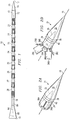
- Fig. 1 is a side view of a penetrator according to the present invention, the penetrator having a plurality of stacked penetrator segments.
- Fig. 2A is a perspective view of a penetrator segment having fins in a stowed position.
- Fig. 2B is a perspective view of a penetrator segment having fins in a deployed position.
- Fig. 3 is a side view of three penetrator segments in a partially deployed configuration.
- Fig. 4 is a cross-sectional view of a fin in its stowed position and contacting the nose portion of a penetrator segment.
- Fig. 1 shows a penetrator 10 having a leading end 12, a trailing end 14, and a longitudinal axis 16 extending between the ends 12 and 14.
- the penetrator 10 is comprised of a plurality of stacked penetrator segments 20 - 28, including a leading penetrator segment 20, seven intermediate penetrator segments 21-27, and a trailing penetrator segment 28.
- Fig. 2A shows a representative individual intermediate penetrator segment, for example, intermediate penetrator segment 21, in a stowed configuration.
- the intermediate penetrator segment 21 has a nose portion 32 and a rear portion 34.
- the exterior surface of the nose portion 32 is tapered in shape.
- the nose portion 32 shown in Fig. 2A is substantially in the shape of a right circular cone which is coaxial with axis 16, but other suitable tapered shapes may be used as well.
- the rear portion 34 is preferably at least substantially in the shape of a right circular cylinder which is also coaxial with axis 16.
- the rear portion 34 further has a rearwardly opening cavity 35 which is shown by a dashed line in Fig. 2A.
- the cavity 35 is preferably tapered in shape so as to be able to accommodate and to be complementary to the tapered shape of a nose portion of another penetrator segment.
- Each of four fins 36A-36D (only 36A and 36B being visible in Fig. 2A) is pivotally mounted to the rear portion 34 so that the fins extend forwardly therefrom when in their stowed positions.
- the fins 36A-36D are shown in their stowed positions wherein the fins 36A-36D are laid alongside the rear portion 34 of the penetrator segment 21 with the longitudinal axis of each fin being at least substantially parallel to the longitudinal axis 16.
- Optional grooves 38 and 40 located between the nose portion 32 and the rear portion 34, allow for the penetrator 10 to be encompassed by a sabot (not shown in these figures).
- a sabot can be used to facilitate the firing of the penetrator 10 from a launch tube, for example, by conforming the outer shape and size of the penetrator 10, including the sabot, to the shape and size of the launch tube. Upon firing the penetrator 10 from the launch tube, the sabot would break apart and fall away from the penetrator 10.
- Fig. 2B shows the penetrator segment 21 with its fins 36A-36D in a deployed position.
- a section 37 of the rear portion 34 has a diameter that is sufficiently smaller than the maximum diameter of the nose portion 32 so that the section 37 of the rear portion 34 can accommodate the fins 36A-36D such that when they are in the stowed position they do not significantly protrude radially outwardly beyond the maximum diameter of the nose portion 32.
- the fins 36A-36D preferably have a curved shape so as to lay smoothly against the curved surface of section 37 of the rear portion 34.
- Fig. 3 shows an intermediate stage in the deployment of the penetrator 10 wherein two intermediate penetrator segments, for example intermediate penetrator segments 25 and 26, are still in the stacked configuration, and a third intermediate penetrator segment 27 has separated from the penetrator segment 26.
- penetrator segment 25 has a nose portion 42, a rear portion 44, fins 46A-46D (46D not visible) in the stowed position and a rearwardly opening cavity 48.
- the penetrator segment 26 has a nose portion 52, a rear portion 54, fins 56A-56D (56D not visible) in the deployed position, and a rearwardly opening cavity 58.
- the nose portion 52 of the penetrator segment 26 is still positioned within the cavity 48 of the penetrator segment 25, so that the penetrator segments 26 and 25 are stacked.
- Each fin for example fin 46A, has a stabilizing portion 60 and a deployment preventing arm 62 on opposite sides of a pivot pin 65.
- the pivot pin 65 runs through a pinhole 66 in the fin 46A and is mounted between two bosses 66A and 66B positioned on either side of the fin 46A(only boss 66A is visible; see also bosses 39A and 39B in Fig. 2B).
- Pivot pin 65 is preferably located in a plane which is perpendicular to the longitudinal axis 16.
- Fig. 4 shows a cross sectional view of fin 46A in its stowed position.
- the stabilizing portion 60 and the deployment preventing arm 62 are positioned on opposite sides of pivot pin 65 around which the stabilizing portion 60 and the arm 62 can rotate.
- the deployment preventing arm 62 of the fin 46A is shown contacting the nose portion 52 of the intermediate penetrator segment 26.
- the contact of the arm 62 with the nose portion 52 prevents the fin 46A from pivoting in an outward direction, thus the fin 46A is restrained in a stowed position with the longitudinal axis of the fin 46A being substantially parallel to the longitudinal axis 16.
- arm 62 contacts the nose portion 52 of the penetrator segment 25, causing the fin 46A to remain forwardly pivoted about pivot pin 65 thereby restraining the fin 46A in a stowed position.
- the fins 56A-56D are free to pivot to their deployed positions wherein the longitudinal axis of each fin 56A-56D is at an angle to the longitudinal axis 16.
- the stabilizing portions 68A-68D (68D not visible) of these fins 56A-56D facilitates the aerodynamic stability of the penetrator segment 26 during flight.
- the deployment of the fins is preferably accomplished by aerodynamic forces acting on the stabilizing portions of the fins.
- deployment may be caused by a suitable mechanism such as by springs bearing the fins toward their deployed position. While four fins have been illustrated for each penetrator segment other than the trailing penetrator segment 28, any suitable number of fins can be employed.
- the penetrator 10 is formed of stacked penetrator segments 20-28. While penetrator 10 is shown to have nine penetrator segments, the penetrator may have any suitable number of penetrator segments, with the potential for destroying a target increasing as more segments are used.
- the shape of each nose portion such as nose portion 52, is complementary to the shape of each cavity, such as cavity 48 so that there is no play or such that there is slight interference between the stacked penetrator segments 20-28.
- the shape of each nose portion and each cavity should be suitably selected to allow the penetrator segments 20-28 to separate due to aerodynamic forces generated upon deployment of the penetrator 10.
- the plurality of stacked penetrator segments 20-28 includes a leading penetrator segment 20 and a trailing penetrator segment 28 which preferably have slightly different characteristics than the intermediate penetrator segments 21-27 as described with respect to Figs. 2A-B, 3 and 4.
- the leading penetrator segment 20 preferably has an elongated nose portion 70 that has a cylindrically shaped base 72 and a tapered tip 74.
- the trailing penetrator segment 28 preferably has an elongated rear portion 82 that has a cylindrically shaped base 84 and an enlarged tail portion 86 that can provide aerodynamic stability to the penetrator 10 before initiation of separation of the penetrator segments.
- the enlarged tail portion 86 is preferably in the form of a frustoconical shape which expands outwardly from front to rear, but can also be in any other suitable shape or in the form of a plurality of fins.
- the flow of air across penetrator segment 27 thereby forces the fins of penetrator segment 27 to pivot to their deployed positions.
- aerodynamic drag against these fins causes the velocity of the penetrator segment 27 to decrease with respect to the remaining stacked penetrator segments 20-26.
- the penetrator segment 27 separates from penetrator segment 26 which then becomes the rearmost penetrator segment of the stacked penetrator segments 20-26.
- the nose portion of the penetrator segment 27 withdraws from the cavity of penetrator segment 26, the nose portion of the penetrator segment 27 no longer contacts the deployment preventing arms of the fins of the penetrator segment 26.
- Fig. 3 is representative of the configuration of penetrator segments 27, 26 and 25 after penetrator 27 has separated from the stacked penetrator segments 20-26.
- Penetrator segment 27 is shown with its fins in their deployed positions and separated from penetrator segment 26. Because the fins of penetrator segment 26 have deployed, penetrator segment 26 will begin separating from penetrator segment 25. Similarly, the remaining stacked penetrator segments 20-24 will each separate from the rearmost intermediate penetrator segment in the stack forwardly until intermediate penetrator segment 21 withdraws from the leading penetrator segment 20.
- the length of the penetrator 10 in the stacked configuration shown in Fig. 1 is less than, and preferably significantly less than, the length of the penetrator in its fully deployed configuration after the penetrator segments 20-28 have separated from each other.
- the penetrator segments 20-28 can be joined in the stacked configuration shown in Fig. 1 by a releasable securing member 90, which runs along the longitudinal axis 16 of the penetrator 10 and through axially aligned bores in the penetrator segments 20-28 (axial bores not shown).
- the securing member 90 can be a rod, wire or cord, for example.
- a release mechanism such as a time-to-go-fuse or explosive bolt, can be used to release the securing member 90 so that the penetrator segments 20-28 can separate from each other.
- the securing member 90 can serve to enhance the rigidity of the penetrator 10 before the penetrator segments 20-28 begin to separate and to control the time during the flight of the penetrator 10 at which the penetrator segments 20-28 begin to separate.
- the securing member 90 is released early in the flight of the penetrator 10 and at a suitably large distance from the intended target, then asymmetric aerodynamic forces acting upon the penetrator segments 20-28 after separation can cause the penetrator segments 20-28 to scatter so that the penetrator segments 20-28 impact the target in multiple locations.
- the penetrator segments 20-28 will be substantially axially aligned upon impacting the target so that the penetrator segments 20-28 will sequentially impact the target in substantially the same location.
- the penetrator segments 20-28 are separated from each other, and the distance between the penetrator segments 20-28 (the amount of separation between immediately adjacent penetrator segments) can be controlled through the use of securing member 90.
- the stacked configuration of the penetrator 10 shown in Fig. 1 can also be described as a plurality of contiguous pairs of penetrator segments, with each contiguous pair having a front penetrator segment and a rear penetrator segment which has its nose positioned in the cavity of the front penetrator segment.
- leading penetrator segment 20 and the forwardmost intermediate penetrator segment 21 form one contiguous pair, with the leading penetrator segment 20 being the front penetrator segment of the pair and the intermediate penetrator segment 21 being the rear penetrator segment of the pair.
- intermediate penetrator segments 21 and 22 form another contiguous pair, with the intermediate penetrator segment 21 being the front penetrator segment of the pair and intermediate penetrator segment 22 being the rear penetrator segment of the pair.
- each contiguous pair of penetrator segments separates by the rear penetrator segment of the pair withdrawing from the cavity of the front penetrator segment of the pair.
- aerodynamic drag against the tail portion 86 of the rear penetrator segment 27 causes the velocity of the rear penetrator segment 28 to decrease with respect to the front penetrator segment 27 and rear penetrator segment 28 thereby separates from the front penetrator segment 27.
- the rearmost contiguous pair of stacked penetrator segments becomes the intermediate penetrator segment 27(the rear penetrator segment of the pair) and the intermediate penetrator segment 26 (the front penetrator segment of the pair). Because the deployment preventing arms of the fins of the rear penetrator segment 27 no longer contact the nose portion of the penetrator segment 28, the fins of the rear penetrator segment 27 are free to deploy. Aerodynamic drag against the stabilizing portions of the thus deployed fins of penetrator segment 27 causes the velocity of the penetrator segment 27 to decrease with respect to the penetrator segment 26, which then causes the penetrator segment 27 to separate from the penetrator segment 26.
- the rearmost contiguous pair of stacked penetrator segments thereby becomes the intermediate penetrator segment 26 (the rear penetrator segment of the pair) and intermediate penetrator segment 25 (the front penetrator segment of the pair).
- intermediate penetrator segment 26 the rear penetrator segment of the pair
- intermediate penetrator segment 25 the front penetrator segment of the pair.
- the contiguous pair formed by intermediate penetrator segments 25 and 24 separates, as do the contiguous pairs formed by intermediate penetrator segments 24 and 23, 23 and 22, and 22 and 21.
- the last (forwardmost) contiguous pair formed by the forwardmost intermediate penetrator segment 21 (the rear penetrator segment of the pair) and the leading penetrator segment 20 (the front penetrator segment of the pair) separates due to the decrease in velocity of the penetrator segment 21 caused by aerodynamic drag against the stabilizing portions of the segment's deployed fins.
Landscapes
- Engineering & Computer Science (AREA)
- Chemical & Material Sciences (AREA)
- Combustion & Propulsion (AREA)
- General Engineering & Computer Science (AREA)
- Current-Collector Devices For Electrically Propelled Vehicles (AREA)
- Moulds For Moulding Plastics Or The Like (AREA)
- Aiming, Guidance, Guns With A Light Source, Armor, Camouflage, And Targets (AREA)
Applications Claiming Priority (2)
| Application Number | Priority Date | Filing Date | Title |
|---|---|---|---|
| US699225 | 1996-08-19 | ||
| US08/699,225 US5834684A (en) | 1996-08-19 | 1996-08-19 | Penetrator having multiple impact segments |
Publications (2)
| Publication Number | Publication Date |
|---|---|
| EP0825412A2 true EP0825412A2 (de) | 1998-02-25 |
| EP0825412A3 EP0825412A3 (de) | 2001-11-14 |
Family
ID=24808427
Family Applications (1)
| Application Number | Title | Priority Date | Filing Date |
|---|---|---|---|
| EP97250215A Withdrawn EP0825412A3 (de) | 1996-08-19 | 1997-07-21 | Wuchtgeschoss mit mehrfachen Schlagwirkungssegmenten |
Country Status (4)
| Country | Link |
|---|---|
| US (1) | US5834684A (de) |
| EP (1) | EP0825412A3 (de) |
| JP (1) | JPH10122800A (de) |
| IL (1) | IL121569A (de) |
Cited By (1)
| Publication number | Priority date | Publication date | Assignee | Title |
|---|---|---|---|---|
| EP0898145A2 (de) | 1997-08-21 | 1999-02-24 | Lockheed Martin Corporation | Penetratorgeschoss mit mehreren Teile, wobei eines dieser Teile ein Explosiv enthält |
Families Citing this family (23)
| Publication number | Priority date | Publication date | Assignee | Title |
|---|---|---|---|---|
| AUPR867101A0 (en) * | 2001-11-02 | 2001-11-29 | Marine Research Wa Pty Ltd | Munitions |
| AUPS182802A0 (en) * | 2002-04-19 | 2002-05-30 | Metal Storm Limited | Projectile sealing arrangement |
| AUPS303702A0 (en) * | 2002-06-20 | 2002-07-11 | Metal Storm Limited | A cartridge assembly for multiple projectiles |
| US6959893B1 (en) * | 2003-04-01 | 2005-11-01 | The United States Of America As Represented By The Secretary Of The Army | Light fighter lethality seeker projectile |
| US7530315B2 (en) | 2003-05-08 | 2009-05-12 | Lone Star Ip Holdings, Lp | Weapon and weapon system employing the same |
| US8661980B1 (en) | 2003-05-08 | 2014-03-04 | Lone Star Ip Holdings, Lp | Weapon and weapon system employing the same |
| AU2003902297A0 (en) * | 2003-05-13 | 2003-07-24 | Metal Storm Limited | External propellant initiation system and projectile |
| US7895946B2 (en) | 2005-09-30 | 2011-03-01 | Lone Star Ip Holdings, Lp | Small smart weapon and weapon system employing the same |
| US7690304B2 (en) | 2005-09-30 | 2010-04-06 | Lone Star Ip Holdings, Lp | Small smart weapon and weapon system employing the same |
| US7448324B1 (en) * | 2006-05-03 | 2008-11-11 | At&T Intellectual Property Ii, L.P. | Segmented rod projectile |
| US8541724B2 (en) | 2006-09-29 | 2013-09-24 | Lone Star Ip Holdings, Lp | Small smart weapon and weapon system employing the same |
| US8117955B2 (en) | 2006-10-26 | 2012-02-21 | Lone Star Ip Holdings, Lp | Weapon interface system and delivery platform employing the same |
| US8707868B2 (en) | 2006-11-30 | 2014-04-29 | The United States Of America As Represented By The Secretary Of The Navy | Pre-compressed penetrator element for projectile |
| USH2230H1 (en) | 2006-11-30 | 2009-08-04 | The United States Of America As Represented By The Secretary Of The Navy | Ceramic and stacked penetrator against a hardened target |
| US8119956B2 (en) * | 2008-10-02 | 2012-02-21 | Raytheon Company | Multi-stage hyper-velocity kinetic energy missile |
| US8438977B2 (en) * | 2008-12-25 | 2013-05-14 | Lockheed Martin Corporation | Projectile having deployable fin |
| US8291828B2 (en) | 2010-03-04 | 2012-10-23 | Glasser Alan Z | High velocity ammunition round |
| US8096243B2 (en) * | 2010-03-04 | 2012-01-17 | Glasser Alan Z | High velocity ammunition round |
| US9068803B2 (en) | 2011-04-19 | 2015-06-30 | Lone Star Ip Holdings, Lp | Weapon and weapon system employing the same |
| US9194678B2 (en) * | 2012-04-25 | 2015-11-24 | Wilcox Industries Corp. | Modular rocket system |
| CN111595209B (zh) * | 2020-05-25 | 2022-06-28 | 宁波曙翔新材料股份有限公司 | 一种穿甲杆 |
| US11685527B2 (en) * | 2020-12-18 | 2023-06-27 | Corvid Technologies LLC | Projectile delivery systems and weaponized aerial vehicles and methods including same |
| DE102021002063A1 (de) | 2021-04-20 | 2022-01-05 | Bundesrepublik Deutschland (Bundesamt für Ausrüstung, Informationstechnik und Nutzung der Bundeswehr) | Penetrator für eine großkalibrige Munition |
Citations (6)
| Publication number | Priority date | Publication date | Assignee | Title |
|---|---|---|---|---|
| US4635556A (en) | 1982-03-17 | 1987-01-13 | Rheinmetall Gmbh | Penetrator shell with stacked core elements |
| US4708064A (en) | 1977-09-29 | 1987-11-24 | Rheinmetall Gmbh | Impact projectile |
| US4716834A (en) | 1980-03-27 | 1988-01-05 | Rheinmetall Gmbh | Inertial penetrator projectile |
| US4901645A (en) | 1980-08-23 | 1990-02-20 | Rheinmetall, Gmbh | Inertial projectile having a breakable pre-penetrator |
| US5088416A (en) | 1978-10-19 | 1992-02-18 | Rheinmetall Gmbh | Impact projectile |
| US5526752A (en) | 1994-09-06 | 1996-06-18 | Rockwell International Corporation | Weapon for destruction of deeply buried and hardened targets |
Family Cites Families (13)
| Publication number | Priority date | Publication date | Assignee | Title |
|---|---|---|---|---|
| US395881A (en) * | 1889-01-08 | Patrick citxxingiiam | ||
| US2804823A (en) * | 1955-05-13 | 1957-09-03 | Jablansky Louis | Multiple unit projectile |
| US4492166A (en) * | 1977-04-28 | 1985-01-08 | Martin Marietta Corporation | Submunition having terminal trajectory correction |
| FR2535450B1 (fr) * | 1981-03-05 | 1986-11-14 | Saint Louis Inst | Projectile perforant |
| DE3207220A1 (de) * | 1982-02-27 | 1983-09-08 | Rheinmetall GmbH, 4000 Düsseldorf | Geschossanordnung |
| US4565340A (en) * | 1984-08-15 | 1986-01-21 | Ford Aerospace & Communications Corporation | Guided projectile flight control fin system |
| DE3609092A1 (de) * | 1986-03-19 | 1990-11-22 | Rheinmetall Gmbh | Geschoss fuer eine rohrwaffe zum bekaempfen aktiv und passiv reagierender sonderpanzerungen |
| FR2609542B1 (fr) * | 1987-01-14 | 1994-05-06 | Serat | Perfectionnements apportes aux projectiles a charges creuses tandem |
| DE3834925A1 (de) * | 1988-10-13 | 1990-04-19 | Siegfried Trost | Huelsenlose munition, fuer insbesondere kalibergleiche sturm-, maschinen- und scharfschuetzengewehre |
| DE3904625A1 (de) * | 1989-02-16 | 1990-08-30 | Diehl Gmbh & Co | Unterkalibriges geschoss |
| DE4007810A1 (de) * | 1990-03-12 | 1991-09-19 | Werner Beiter | Pfeilspitze |
| USH905H (en) * | 1990-09-13 | 1991-04-02 | The United States Of America As Represented By The Secretary Of The Army | Fin assembly |
| FR2718842B1 (fr) * | 1994-04-15 | 1996-06-28 | Luchaire Defense Sa | Projectile destiné à agresser des cibles dures. |
-
1996
- 1996-08-19 US US08/699,225 patent/US5834684A/en not_active Expired - Fee Related
-
1997
- 1997-07-21 EP EP97250215A patent/EP0825412A3/de not_active Withdrawn
- 1997-08-18 IL IL12156997A patent/IL121569A/en not_active IP Right Cessation
- 1997-08-19 JP JP9236498A patent/JPH10122800A/ja active Pending
Patent Citations (6)
| Publication number | Priority date | Publication date | Assignee | Title |
|---|---|---|---|---|
| US4708064A (en) | 1977-09-29 | 1987-11-24 | Rheinmetall Gmbh | Impact projectile |
| US5088416A (en) | 1978-10-19 | 1992-02-18 | Rheinmetall Gmbh | Impact projectile |
| US4716834A (en) | 1980-03-27 | 1988-01-05 | Rheinmetall Gmbh | Inertial penetrator projectile |
| US4901645A (en) | 1980-08-23 | 1990-02-20 | Rheinmetall, Gmbh | Inertial projectile having a breakable pre-penetrator |
| US4635556A (en) | 1982-03-17 | 1987-01-13 | Rheinmetall Gmbh | Penetrator shell with stacked core elements |
| US5526752A (en) | 1994-09-06 | 1996-06-18 | Rockwell International Corporation | Weapon for destruction of deeply buried and hardened targets |
Cited By (1)
| Publication number | Priority date | Publication date | Assignee | Title |
|---|---|---|---|---|
| EP0898145A2 (de) | 1997-08-21 | 1999-02-24 | Lockheed Martin Corporation | Penetratorgeschoss mit mehreren Teile, wobei eines dieser Teile ein Explosiv enthält |
Also Published As
| Publication number | Publication date |
|---|---|
| IL121569A0 (en) | 1998-02-08 |
| EP0825412A3 (de) | 2001-11-14 |
| IL121569A (en) | 2001-04-30 |
| US5834684A (en) | 1998-11-10 |
| JPH10122800A (ja) | 1998-05-15 |
Similar Documents
| Publication | Publication Date | Title |
|---|---|---|
| US5834684A (en) | Penetrator having multiple impact segments | |
| US5988071A (en) | Penetrator having multiple impact segments, including an explosive segment | |
| US6021716A (en) | Penetrator having multiple impact segments | |
| US6367388B1 (en) | Ammunition cartridge with differently packed shotshell wad projectile chambers | |
| JP4199118B2 (ja) | 複数の発射体が整列される弾頭 | |
| ES2273375T3 (es) | Proyectil o cabeza de combate. | |
| JP4057590B2 (ja) | タンデム弾頭 | |
| US4648324A (en) | Projectile with enhanced target penetrating power | |
| EP3105538B1 (de) | Munition mit penetrator und einem externen kabelbaum | |
| US3903804A (en) | Rocket-propelled cluster weapon | |
| US8661980B1 (en) | Weapon and weapon system employing the same | |
| US4708064A (en) | Impact projectile | |
| US20110179963A1 (en) | Weapon and Weapon System Employing the Same | |
| JP4430070B2 (ja) | 放出角度が低減された運動エネルギー式ロッド型弾頭 | |
| EP0350821A2 (de) | Gefechtskopf | |
| US4080900A (en) | Projectile | |
| JPH06147797A (ja) | 演習用発射体 | |
| US8222583B2 (en) | Drag-stabilized water-entry projectile and cartridge assembly | |
| US3677179A (en) | Telescoping ordnance device | |
| US3427976A (en) | Ordnance projectile | |
| EP0298494B1 (de) | Submunitions-Wirkteil, sowie Flechettes-Gefechtskopf und Flechettes dafür | |
| US6662726B1 (en) | Kinetic energy penetrator | |
| US6899034B1 (en) | Controlled energy release projectile | |
| US7503261B2 (en) | Universal KE projectile, in particular for medium caliber munitions | |
| US9476682B1 (en) | Multi-charge munitions, incorporating hole-boring charge assemblies |
Legal Events
| Date | Code | Title | Description |
|---|---|---|---|
| PUAI | Public reference made under article 153(3) epc to a published international application that has entered the european phase |
Free format text: ORIGINAL CODE: 0009012 |
|
| AK | Designated contracting states |
Kind code of ref document: A2 Designated state(s): AT BE CH DE DK ES FI FR GB GR IE IT LI LU MC NL PT SE |
|
| PUAL | Search report despatched |
Free format text: ORIGINAL CODE: 0009013 |
|
| AK | Designated contracting states |
Kind code of ref document: A3 Designated state(s): AT BE CH DE DK ES FI FR GB GR IE IT LI LU MC NL PT SE |
|
| AKX | Designation fees paid | ||
| REG | Reference to a national code |
Ref country code: DE Ref legal event code: 8566 |
|
| STAA | Information on the status of an ep patent application or granted ep patent |
Free format text: STATUS: THE APPLICATION IS DEEMED TO BE WITHDRAWN |
|
| 18D | Application deemed to be withdrawn |
Effective date: 20020515 |