EP0825304B1 - Apparatus for separating floating and non-floating particulate from rainwater drainage - Google Patents
Apparatus for separating floating and non-floating particulate from rainwater drainage Download PDFInfo
- Publication number
- EP0825304B1 EP0825304B1 EP97650036A EP97650036A EP0825304B1 EP 0825304 B1 EP0825304 B1 EP 0825304B1 EP 97650036 A EP97650036 A EP 97650036A EP 97650036 A EP97650036 A EP 97650036A EP 0825304 B1 EP0825304 B1 EP 0825304B1
- Authority
- EP
- European Patent Office
- Prior art keywords
- drain water
- floating
- tank
- water
- outlet
- Prior art date
- Legal status (The legal status is an assumption and is not a legal conclusion. Google has not performed a legal analysis and makes no representation as to the accuracy of the status listed.)
- Expired - Lifetime
Links
Images


Classifications
-
- E—FIXED CONSTRUCTIONS
- E03—WATER SUPPLY; SEWERAGE
- E03F—SEWERS; CESSPOOLS
- E03F5/00—Sewerage structures
- E03F5/14—Devices for separating liquid or solid substances from sewage, e.g. sand or sludge traps, rakes or grates
- E03F5/16—Devices for separating oil, water or grease from sewage in drains leading to the main sewer
-
- B—PERFORMING OPERATIONS; TRANSPORTING
- B01—PHYSICAL OR CHEMICAL PROCESSES OR APPARATUS IN GENERAL
- B01D—SEPARATION
- B01D21/00—Separation of suspended solid particles from liquids by sedimentation
- B01D21/0087—Settling tanks provided with means for ensuring a special flow pattern, e.g. even inflow or outflow
-
- B—PERFORMING OPERATIONS; TRANSPORTING
- B01—PHYSICAL OR CHEMICAL PROCESSES OR APPARATUS IN GENERAL
- B01D—SEPARATION
- B01D21/00—Separation of suspended solid particles from liquids by sedimentation
- B01D21/26—Separation of sediment aided by centrifugal force or centripetal force
- B01D21/267—Separation of sediment aided by centrifugal force or centripetal force by using a cyclone
-
- E—FIXED CONSTRUCTIONS
- E03—WATER SUPPLY; SEWERAGE
- E03F—SEWERS; CESSPOOLS
- E03F5/00—Sewerage structures
- E03F5/12—Emergency outlets
- E03F5/125—Emergency outlets providing screening of overflowing water
-
- E—FIXED CONSTRUCTIONS
- E03—WATER SUPPLY; SEWERAGE
- E03F—SEWERS; CESSPOOLS
- E03F5/00—Sewerage structures
- E03F5/14—Devices for separating liquid or solid substances from sewage, e.g. sand or sludge traps, rakes or grates
-
- B—PERFORMING OPERATIONS; TRANSPORTING
- B01—PHYSICAL OR CHEMICAL PROCESSES OR APPARATUS IN GENERAL
- B01D—SEPARATION
- B01D2221/00—Applications of separation devices
- B01D2221/12—Separation devices for treating rain or storm water
Definitions
- the present invention relates to a containment system that separates floating and non-floating particulate, such as oil and sand respectively, from water drainage and in particular to a containment system which is more efficient than the prior art.
- U. S. Patent No. 601,794 discloses a catch basin for sewers intended to remove dirt and trash from water that has run off a street.
- U. S. Patent No. 1,675,714 discloses a catch basin which is intended to catch debris or trash of the nature that would obstruct the sewer. This invention lacks means for separating floating particulate from the rain water.
- U.S. Patent No. 3,815,749 discloses a street drain to be used in conjunction with a sewage system in which there is a water collection basin and a dry well. There are two discharge openings, one to discharge to the dry well and the other to discharge to the sewer system.
- U. S. Patent No. 4,363,731 discloses a device for regulating the rate of flow of waste water that is mixed with rainwater by passing the mixture through a series of orifices.
- U. S. Patent No. 4,935,132 discloses a drain pipe filter which is intended to separate oily contaminants exiting a floating drain. This device is not intended to separate solid particulate from rainwater in the manner of the present invention.
- U. S. Patent No. 4,983,295 discloses a cylindrical vessel in which floatable and non-floatable particulates that are suspended in water are separated by means of rotational movement of the water.
- U. S. Patent No 4,985,148 discloses a separator tank for rain and waste water wherein the water is introduced and forced to travel through a pre-defined passage leading to an exit pipe. This invention does not provide means for separating floatable particulate when an overflow condition, as may be encountered during an intense rainfall, occurs
- German Utility Patent No. 9,100,565 U discloses an apparatus for providing some filtering of overflow waste water.
- a retention pond of horizontally arranged screens allows for some filtering of coarse matter.
- DE-A-4,242,519 discloses an apparatus for separating floating matter from a waste water stream diverted from a main sewage pipeline.
- DE-A-19,501,034 discloses an apparatus comprising a conical tank with a vertical partition within the tank for separating floating matter from a liquid, in particular sewage. Non-floating matter is allowed to settle within the tank, after which it may be removed.
- a further object of the present invention is to remove large amounts of surface run-off water, especially during a storm, separating residues contained in such water, and processing the water in such a way that no water builds up on the street, which would result in flooding conditions.
- the potential-toxic and environmentally unsafe nature of this collected particulate makes this invention an important safeguard to both cleaning drainage water and removal of dangerous contaminants.
- the present invention accordingly provides an apparatus for separating floating and non-floating particulate from drain water as set out in the appended claims.
- the present invention has a tank defining a chamber with an inlet and an outlet.
- a bulkhead with openings is spaced opposite the inlet and extends from the base of the chamber.
- a baffle is located between the bulkhead and the outlet and extends from the top of the chamber to near the bottom.
- An orifice plate or plates and a weir plate are adjustably mounted in series with a pair of vertically spaced outlets of the flow control chamber and control the rate of flow therethrough.
- the system is seen as having four sections, namely, a non-floating particulate containment chamber a floating particulate containment chamber, a flow control chamber; and an outlet chamber. It is to be understood that each of the noted chambers may be of the same size, that they may each be of a different size, or that several may be of the same size while others may be of different size, without deviating from the basic operation of the invention.
- the invention 10 is shown in Fig. 1 in perspective view and includes a tank 12, an inlet pipe 14, a bulkhead 16, baffle 18, at least one removable cover 20, orifice plate 22 and weir plate 23, low-level outlet 24, and high-level outlet 26, openings 28 and 29 in bulkhead 16, and an outlet pipe 30.
- a tank 12 an inlet pipe 14
- a bulkhead 16 baffle 18, at least one removable cover 20, orifice plate 22 and weir plate 23, low-level outlet 24, and high-level outlet 26, openings 28 and 29 in bulkhead 16, and an outlet pipe 30.
- the bulkhead 16 and the wall of the tank 12 make a generally ovate or circular non-floating particulate containment chamber and that the inlet pipe is axially offset from the center of this chamber.
- bulkhead 16 can be, but is not limited to a circular wall configuration.
- the non-floatable particulate entrained therein are contained by bulkhead 16.
- the bulkhead openings 28 and 29 allow passage of water.
- the bulkhead is constructed such that the floatable particulate flows through the bulkhead All of the floatable particulate is to be contained by the baffle 18.
- the arrows in Fig. 2 show the drainage path taken by the rainwater through the subject invention.
- Figs. 3A to 3F show the present invention during different stages of operation.
- the phantom line in Fig. 3A indicates the water level 50 before or after a drainage event when there is little or no drainage flow.
- the phantom line in Fig. 3B indicates the water level 50 during the initial phase of operation with non-floatable particulate being retained by bulkhead 16 and floatable particulate by baffle 18.
- the phantom line in Fig. 3C indicates the water level 50 during the transitional phase of operation as the volume of flow increases.
- the phantom line in Fig. 3D indicates the water level 50 during full capacity phase operation.
- the phantom line in Fig. 3E indicates the water level 50 which decreases during the phase in which water ceases to enter the invention 10.
- the phantom line in Fig. 3F indicates the water level 50 after all drainage has ceased, and the non floating particulate containment chamber 31 has been cleaned.
- the tank 12 preferably, has a volume in the range of 2,83 to 28,31 m 3 (one hundred to one thousand cubic feet) with overall dimensions of 1,22 to 3,05 m (four to ten feet) wide, by 2,43 to 5,49 m (eight to eighteen feet) long, by 1,22 to 3,35 m (four to eleven feet) high.
- the inlet pipe 14 is, preferably, in the range of 0,30 to 0,91 m (one to three feet) in diameter.
- the bulkhead 16 is, preferably, from about 0,91 m (three feet) high to the height of the tank and the size of the opening under the baffle is in the range of 0,30 to 0,91 m (one to three feet) and is the width of the tank.
- the low-level outlet 24 is in the range of 0,30 to 0,91 m (one to three feet) in a generally rectangular orientation.
- the high-level outlet 26 is, preferably, in the range of 0,61 to 1,22 m (two to four feet) in a generally rectangular orientation.
- the removable covers are preferably 0,30 to 0,91 m (one to three feet) in diameter and preferably are made of cast iron.
- the outlet chamber 34 preferably, has a volume of 1,42 to 8,50 m 2 (fifty to three hundred cubic feet) and is preferably substantially equal in volume to the flow control chamber 33.
- the non-floating particulate containment chamber 31 and the floating particulate containment chamber 32 have been show substantially the same size Cor convenience of the drawings only.
- containment chambers do not have to be similarly sized and therefore it is within the scope of the present invention to have the two chambers of different size in accordance with local drainage requirements.
- pipes are made of materials selected for durability and resistance, especially non reaction to the composition of the materials contained in the flow.
- the pipes are made of plastic.
- the tank, bulkhead, and baffle are preferably made of concrete, although other materials may also be used.
- the overall water level rises as the water flows through the openings 28 and 29 and exits through the low-level outlet 24 at a rate controlled by the orifice plate 22.
- the orifice plate 22 is slightly higher then the opening 29 thereby allowing skimming of the non-floating particulate into the containment chamber during cleaning.
- the overall water level rises because the inlet flow rate exceeds the outlet flow rate. This is referred to as the initial phase, as shown in Fig. 3B.
- the transition phase As shown in Fig. 3C, the vertical separation distance between the floating particulate and the bottom of the baffle 18 increases.
- the water level rises to the level of the high level outlet 26, as shown in Fig. 3D.
- the rate of flow of the exiting water is increasing slightly as the water level is increasing but is still controlled by the orifice plate 22. This continues until the water level rises above the opening in the weir plate 23 at the high level outlet 26. At this point the flow rate through the tank 12 begins to increase significantly.
- the high outlet 26 is controlled by plate 23 which is designed to transfer as much water as the outlet pipe 30 can discharge. This continues until the rate at which the water is introduced through the inlet 14 decreases to the point where the water level drops below the level of the high-level outlet 26. The remaining water in the tank 12 is discharged at a rate determined by the orifice plate 22. Eventually the water level drops to the invert elevation of the orifice plate 22 which covers the low level outlet 24 as shown in Fig 3E Now the point has been reached where there is no flow through the tank 12.
- the overall low water level as shown in Fig. 3E is an important feature of the invention 10 because it permits an easy inspection. It is anticipated that the level of particulate accumulation can be determined for example by removing covers 20 to see if there is enough accumulated floating and non-floating particulate to necessitate the cleaning of the tank 12.
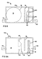
- Fig. 5 shows the preferred embodiment of the bulkhead 16.
- the incoming flow is deflected by the curved wall of the non-floating particulate 31 chamber creating a swirling action Once the fluids drain, the swirling action continues to prevent the non-floating particulate from being carried through the bulkhead openings.
- openings in the bulkhead may be either substantially rectangular or circular.
- the only general restriction is that no openings should be substantially opposite the inlet to avoid non floating material from being carried through the bulkhead by shear force of the flow.
- opening 28 should be no lower than the midpoint of the inlet pipe for substantially the same reason.
- Figs 6 and 7 show preferred embodiments of the weir plate and orifice plate with profiled openings to control flow to the outlet pipe 30.
- the vertical slots are for adjustable mounting of the plates.
- Other opening profiles are also possible, for example, using only one aperture and plate which may produce a varying aperture for controlling flow through the outlet chamber 34
- the single plate and single aperture shown in Fig. 8 provides a single means for controlling water level in the movement of the water from the flow control chamber 33 to the outlet chamber 34.
- the wide upper section of the single aperture accommodates larger volumes of water experienced with high water levels, while the narrow lower section accommodates less water volume at low water levels.
- variations in a single aperture shape may provide suitable water flow control.
- Figs. 9 and 9A show a horizontal section view showing an alternate embodiment 10a of the present invention.
- This embodiment 10a includes an alternative means for controlling the flow of water from the separation tank to the outlet portion of an alternative tank 12a of the present invention.
- This alternative means would be used in place of the weir plate and orifice designed to control high-level and low-level water flow rates, respectively.
- Screen capture channels 90 allow a lower screen portion 91 and an upper screen portion 92 to be removeably dropped into place
- Lower screen portion 91 is a fine-mesh screen that filters out small particulates that may be transferred from the floating and non-floating particulate section of the tank.
- Upper portion 92 is a coarse-mesh screen that filters out relatively large particulates from the floating and non-floating particulate sections. All other elements of the tank 12a remain the same as referenced with respect to Fig. 1.
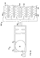
- Fig. 10 shows a schematic diagram of the present invention as shown in Fig. 1 in combination with a downstream fluid distribution system 100, such as, for example, a retention area 100 that is external to the tank 12.
- the retention area 100 can be of any one of a variety of commonly known designs capable of receiving drain water from the tank 12 by way of a distributor such as one or more distribution tubes 101.
- the distribution tubes may have perforations 102, as shown, when used in conjunction with a porous filtering bed, such as sand 103 that forms the retention area 100. Any material similar to sand 103 may be used to disperse the drain water so long as it provides good percolation characteristics, including, but not limited to, peat and compost filtering media, for example.
- the retention area 100 may be a simple holding tank, with the distribution tubes 101 being non-perforated.
- Figs. 11 and 11A show a schematic diagram of an alternative embodiment of the present invention in combination with a detention basin 111
- the detention basin 111 is used for diverting higher drain water flow rates than those permitted under most regulatory requirements.
- a supplemental tank discharge 112 is shown in addition to outlet pipe 30 for the purpose of transferring such sudden flow occurrences. Excessive drain water exits from tank 12b through discharge 112 to detention basin 111.
- a return 113 is provided to move drain water out of the detention basin 111 utilizing a one-way valve 114 of the type known to those skilled in the art. The one-way valve permits the return of water from the detention basin 111 only after the sudden influx has passed. While Figs. 10, 11, and 11A show two particular types of output receiving means, it should be noted that any other type of output receiving means for holding or dispersing drain water may be utilized without straying from the intended scope of the present invention.
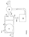
- Fig. 12 is a schematic diagram of the present invention as shown in Fig.1 in combination with an oil/water separator 120.
- the separator 120 is shown connected to a low-flow outlet 30b via oritice 22.
- a high-flow outlet 30a is connected to weir 23.
- the low-flow discharge runs through separator 120 where oil coalesces out of the drain water.
- the two flows paths reconnect at connector 121 and to outlet pipe 30.
- separator 120 is shown, it is noted that any drain water treatment device may be used in a manner similar to that of the separator 120 shown in Fig. 12. It has been observed that a separator such as the ECOSTAR(TM) oil/water separator made available by Environment XXI of East Pembroke, New York, would be a suitable add-on separator to the tank 12 of the present invention.
Description
- The present invention relates to a containment system that separates floating and non-floating particulate, such as oil and sand respectively, from water drainage and in particular to a containment system which is more efficient than the prior art.
- The art of controlling drainage water is very old. There have been many attempts to provide systems which will separate materials entrained in the water so that substantially only water flows past the catch basin or trap. The following discussion covers some of the many known approaches to solving this problem.
- U. S. Patent No. 601,794 discloses a catch basin for sewers intended to remove dirt and trash from water that has run off a street.
- U. S. Patent No. 1,675,714 discloses a catch basin which is intended to catch debris or trash of the nature that would obstruct the sewer. This invention lacks means for separating floating particulate from the rain water.
- U.S. Patent No. 3,815,749 discloses a street drain to be used in conjunction with a sewage system in which there is a water collection basin and a dry well. There are two discharge openings, one to discharge to the dry well and the other to discharge to the sewer system.
- U. S. Patent No. 4,363,731 discloses a device for regulating the rate of flow of waste water that is mixed with rainwater by passing the mixture through a series of orifices.
- U. S. Patent No. 4,935,132 discloses a drain pipe filter which is intended to separate oily contaminants exiting a floating drain. This device is not intended to separate solid particulate from rainwater in the manner of the present invention.
- U. S. Patent No. 4,983,295 discloses a cylindrical vessel in which floatable and non-floatable particulates that are suspended in water are separated by means of rotational movement of the water.
- U. S. Patent No 4,985,148 discloses a separator tank for rain and waste water wherein the water is introduced and forced to travel through a pre-defined passage leading to an exit pipe. This invention does not provide means for separating floatable particulate when an overflow condition, as may be encountered during an intense rainfall, occurs
- German Utility Patent No. 9,100,565 U discloses an apparatus for providing some filtering of overflow waste water. A retention pond of horizontally arranged screens allows for some filtering of coarse matter.
- DE-A-4,242,519 discloses an apparatus for separating floating matter from a waste water stream diverted from a main sewage pipeline.
- DE-A-19,501,034 discloses an apparatus comprising a conical tank with a vertical partition within the tank for separating floating matter from a liquid, in particular sewage. Non-floating matter is allowed to settle within the tank, after which it may be removed.
- It is an object of the present invention to remove floating and non-floating particulate from run off water during either sudden storms or steady prolonged rainfalls.
- A further object of the present invention is to remove large amounts of surface run-off water, especially during a storm, separating residues contained in such water, and processing the water in such a way that no water builds up on the street, which would result in flooding conditions.
- It is a further object of the present invention to provide a safe and effective means to collect, remove, and dispose of accumulated floating and non-floating particulate. The potential-toxic and environmentally unsafe nature of this collected particulate makes this invention an important safeguard to both cleaning drainage water and removal of dangerous contaminants.
- The present invention accordingly provides an apparatus for separating floating and non-floating particulate from drain water as set out in the appended claims.
- The present invention has a tank defining a chamber with an inlet and an outlet. A bulkhead with openings is spaced opposite the inlet and extends from the base of the chamber. A baffle is located between the bulkhead and the outlet and extends from the top of the chamber to near the bottom. An orifice plate or plates and a weir plate are adjustably mounted in series with a pair of vertically spaced outlets of the flow control chamber and control the rate of flow therethrough. The system is seen as having four sections, namely, a non-floating particulate containment chamber a floating particulate containment chamber, a flow control chamber; and an outlet chamber. It is to be understood that each of the noted chambers may be of the same size, that they may each be of a different size, or that several may be of the same size while others may be of different size, without deviating from the basic operation of the invention.
- The present invention will now be described, by way of example, with reference to the accompanying drawings in which:
- Fig. 1 is a perspective view of the preferred embodiment partially broken away to reveal the bulkhead, openings, baffle and control outlet(s);
- Fig. 2 is a horizontal section through the present invention looking from top to bottom.
- Fig. 3A is a side elevation, partially broken away, showing the subject invention in a dry weather condition;
- Fig. 38 is a view similar to Fig. 3A showing the subject invention during the initial phase of operation;
- Fig. 3C is a view similar to Fig. 3A showing the subject invention during the transitional phase of operation;
- Fig. 3D is a view similar to Fig. 3A showing the present invention during full capacity phase of operation;
- Fig. 3E is a view similar to Fig. 3A showing the present invention during the final phase of operation when water ceases to enter the apparatus;
- Fig. 3F is a view similar to Fig. 3A showing the present invention after the collected non-floating particulate has been removed and drainage has ceased;
- Fig. 4 is a longitudinal vertical section through the present invention;
- Fig. 5 is a transverse vertical section taken along line 5-5 of Fig. 4;
- Fig. 6 and 7 are enlarged elevations of the preferred embodiments of the weir plate and orifice plate, respectively.
- Fig. 8 is an enlarged elevation that combines Figures 6 & 7 into an alternative flow control embodiment.
- Fig. 9 is a horizontal section view showing an alternate embodiment of the present invention.
- Fig. 9A is a side elevation view of the alternative embodiment in Fig. 9.
- Fig. 10 is a schematic diagram of the present invention as shown in Fig. 1 in combination with a sand-filter.
- Fig. 11 is a schematic diagram of an alternative embodiment of the present invention in combination with a detention basin.
- Fig. 11A is a side view of the alternative embodiment in Fig. 11.
- Fig. 12 is a schematic diagram of the present invention as shown in Fig. 1 in combination with an oil/water separator.
-
- The
invention 10 is shown in Fig. 1 in perspective view and includes atank 12, aninlet pipe 14, abulkhead 16,baffle 18, at least oneremovable cover 20,orifice plate 22 andweir plate 23, low-level outlet 24, and high-level outlet 26,openings bulkhead 16, and anoutlet pipe 30. It will be noted, from Fig. 2, that thebulkhead 16 and the wall of thetank 12 make a generally ovate or circular non-floating particulate containment chamber and that the inlet pipe is axially offset from the center of this chamber. It is anticipated thatbulkhead 16 can be, but is not limited to a circular wall configuration. - The water enters the subject invention through
inlet pipe 14 and, due to the offset of the pipe and chamber shape, a swirling motion is imparted to the flow. The non-floatable particulate entrained therein are contained bybulkhead 16. Thebulkhead openings baffle 18. - The
orifice plate 22, through which the low level water exits, controls the low level water flow. Theweir plate 23, through which the high level water exits controls the high level water flow. The arrows in Fig. 2 show the drainage path taken by the rainwater through the subject invention. - Figs. 3A to 3F show the present invention during different stages of operation. The phantom line in Fig. 3A indicates the
water level 50 before or after a drainage event when there is little or no drainage flow. The phantom line in Fig. 3B indicates thewater level 50 during the initial phase of operation with non-floatable particulate being retained bybulkhead 16 and floatable particulate bybaffle 18. The phantom line in Fig. 3C indicates thewater level 50 during the transitional phase of operation as the volume of flow increases. The phantom line in Fig. 3D indicates thewater level 50 during full capacity phase operation. The phantom line in Fig. 3E indicates thewater level 50 which decreases during the phase in which water ceases to enter theinvention 10. The phantom line in Fig. 3F indicates thewater level 50 after all drainage has ceased, and the non floatingparticulate containment chamber 31 has been cleaned. - The
tank 12, preferably, has a volume in the range of 2,83 to 28,31 m3 (one hundred to one thousand cubic feet) with overall dimensions of 1,22 to 3,05 m (four to ten feet) wide, by 2,43 to 5,49 m (eight to eighteen feet) long, by 1,22 to 3,35 m (four to eleven feet) high. Theinlet pipe 14 is, preferably, in the range of 0,30 to 0,91 m (one to three feet) in diameter. Thebulkhead 16 is, preferably, from about 0,91 m (three feet) high to the height of the tank and the size of the opening under the baffle is in the range of 0,30 to 0,91 m (one to three feet) and is the width of the tank. - The low-
level outlet 24 is in the range of 0,30 to 0,91 m (one to three feet) in a generally rectangular orientation. The high-level outlet 26 is, preferably, in the range of 0,61 to 1,22 m (two to four feet) in a generally rectangular orientation The removable covers are preferably 0,30 to 0,91 m (one to three feet) in diameter and preferably are made of cast iron. Theoutlet chamber 34, preferably, has a volume of 1,42 to 8,50 m2 (fifty to three hundred cubic feet) and is preferably substantially equal in volume to theflow control chamber 33. The non-floatingparticulate containment chamber 31 and the floatingparticulate containment chamber 32 have been show substantially the same size Cor convenience of the drawings only. - Additionally, the containment chambers do not have to be similarly sized and therefore it is within the scope of the present invention to have the two chambers of different size in accordance with local drainage requirements.
- Preferably all pipes are made of materials selected for durability and resistance, especially non reaction to the composition of the materials contained in the flow. Preferably, the pipes are made of plastic. The tank, bulkhead, and baffle are preferably made of concrete, although other materials may also be used.
- In use, water drainage possibly mixed with sewage, will enter the
tank 12 through theinlet 14, resulting in a swirling motion being imparted thereto. Initial drainage at very low levels begins throughopening 29. As flow levels increase, the water level rises behind thebulkhead 16 until it is higher than the crest of opening 28 at which point the water level rises in the rest of thetank 12. Oil and other floating particulate, which are mixed in the water rise along with the overall water level. - The overall water level rises as the water flows through the
openings level outlet 24 at a rate controlled by theorifice plate 22. Theorifice plate 22 is slightly higher then theopening 29 thereby allowing skimming of the non-floating particulate into the containment chamber during cleaning. The overall water level rises because the inlet flow rate exceeds the outlet flow rate. This is referred to as the initial phase, as shown in Fig. 3B. - During the next phase, referred to as the transition phase, as shown in Fig. 3C, the vertical separation distance between the floating particulate and the bottom of the
baffle 18 increases. The water level rises to the level of thehigh level outlet 26, as shown in Fig. 3D. The rate of flow of the exiting water is increasing slightly as the water level is increasing but is still controlled by theorifice plate 22. This continues until the water level rises above the opening in theweir plate 23 at thehigh level outlet 26. At this point the flow rate through thetank 12 begins to increase significantly. - During the next phase, referred to as the full capacity phase, as shown in Fig 3D, the
high outlet 26 is controlled byplate 23 which is designed to transfer as much water as theoutlet pipe 30 can discharge. This continues until the rate at which the water is introduced through theinlet 14 decreases to the point where the water level drops below the level of the high-level outlet 26. The remaining water in thetank 12 is discharged at a rate determined by theorifice plate 22. Eventually the water level drops to the invert elevation of theorifice plate 22 which covers thelow level outlet 24 as shown in Fig 3E Now the point has been reached where there is no flow through thetank 12. - The overall low water level as shown in Fig. 3E is an important feature of the
invention 10 because it permits an easy inspection. It is anticipated that the level of particulate accumulation can be determined for example by removingcovers 20 to see if there is enough accumulated floating and non-floating particulate to necessitate the cleaning of thetank 12. - Fig. 5 shows the preferred embodiment of the
bulkhead 16. The incoming flow is deflected by the curved wall of the non-floating particulate 31 chamber creating a swirling action Once the fluids drain, the swirling action continues to prevent the non-floating particulate from being carried through the bulkhead openings. - It is contemplated that other patterned arrays of openings in the bulkhead may be either substantially rectangular or circular. The only general restriction is that no openings should be substantially opposite the inlet to avoid non floating material from being carried through the bulkhead by shear force of the flow. Also opening 28 should be no lower than the midpoint of the inlet pipe for substantially the same reason.
- Figs 6 and 7 show preferred embodiments of the weir plate and orifice plate with profiled openings to control flow to the
outlet pipe 30. The vertical slots are for adjustable mounting of the plates. Other opening profiles are also possible, for example, using only one aperture and plate which may produce a varying aperture for controlling flow through theoutlet chamber 34 For example, the single plate and single aperture shown in Fig. 8 provides a single means for controlling water level in the movement of the water from theflow control chamber 33 to theoutlet chamber 34. In that embodiment of the invention the wide upper section of the single aperture accommodates larger volumes of water experienced with high water levels, while the narrow lower section accommodates less water volume at low water levels. Of course, it is to be understood that variations in a single aperture shape may provide suitable water flow control. - Figs. 9 and 9A show a horizontal section view showing an
alternate embodiment 10a of the present invention. Thisembodiment 10a includes an alternative means for controlling the flow of water from the separation tank to the outlet portion of analternative tank 12a of the present invention. This alternative means would be used in place of the weir plate and orifice designed to control high-level and low-level water flow rates, respectively.Screen capture channels 90 allow alower screen portion 91 and anupper screen portion 92 to be removeably dropped into placeLower screen portion 91 is a fine-mesh screen that filters out small particulates that may be transferred from the floating and non-floating particulate section of the tank.Upper portion 92 is a coarse-mesh screen that filters out relatively large particulates from the floating and non-floating particulate sections. All other elements of thetank 12a remain the same as referenced with respect to Fig. 1. - Fig. 10 shows a schematic diagram of the present invention as shown in Fig. 1 in combination with a downstream
fluid distribution system 100, such as, for example, aretention area 100 that is external to thetank 12. Theretention area 100 can be of any one of a variety of commonly known designs capable of receiving drain water from thetank 12 by way of a distributor such as one ormore distribution tubes 101. The distribution tubes may haveperforations 102, as shown, when used in conjunction with a porous filtering bed, such assand 103 that forms theretention area 100. Any material similar tosand 103 may be used to disperse the drain water so long as it provides good percolation characteristics, including, but not limited to, peat and compost filtering media, for example. Alternatively, theretention area 100 may be a simple holding tank, with thedistribution tubes 101 being non-perforated. - Figs. 11 and 11A show a schematic diagram of an alternative embodiment of the present invention in combination with a
detention basin 111 Thedetention basin 111 is used for diverting higher drain water flow rates than those permitted under most regulatory requirements. Asupplemental tank discharge 112 is shown in addition tooutlet pipe 30 for the purpose of transferring such sudden flow occurrences. Excessive drain water exits fromtank 12b throughdischarge 112 todetention basin 111. Areturn 113 is provided to move drain water out of thedetention basin 111 utilizing a one-way valve 114 of the type known to those skilled in the art. The one-way valve permits the return of water from thedetention basin 111 only after the sudden influx has passed. While Figs. 10, 11, and 11A show two particular types of output receiving means, it should be noted that any other type of output receiving means for holding or dispersing drain water may be utilized without straying from the intended scope of the present invention. - Additionally, any number of supplemental items designed to enhance the effectiveness of the
tank 12 of the present invention may be coupled to the tank, including, but not limited to, placement proximate to the area ofoutlet pipe 30. For example, Fig. 12 is a schematic diagram of the present invention as shown in Fig.1 in combination with an oil/water separator 120. Theseparator 120 is shown connected to a low-flow outlet 30b viaoritice 22. A high-flow outlet 30a is connected toweir 23. The low-flow discharge runs throughseparator 120 where oil coalesces out of the drain water. The two flows paths reconnect atconnector 121 and tooutlet pipe 30. Althoughseparator 120 is shown, it is noted that any drain water treatment device may be used in a manner similar to that of theseparator 120 shown in Fig. 12. It has been observed that a separator such as the ECOSTAR(TM) oil/water separator made available by Environment XXI of East Pembroke, New York, would be a suitable add-on separator to thetank 12 of the present invention. - The present invention may be subject to many modifications and changes without departing from the scope of the present invention as defined in the appended claims.
Claims (8)
- An apparatus for separating floating and non-floating particulates from drain water under relatively higher drain water flow rates such as occur during sudden storms and under relatively lower drain water flow rates such as occur during steady prolonged rainfall, the apparatus comprising a tank (12) for separating floating and non-floating particulates having an inlet (14) for introducing drain water and an outlet (30) for discharging the drain water,
a substantially cylindrical bulkhead (16) containment wall defining a chamber (31) for containing non-floating particulate under either flow rate and for inducing swirling of the drain water within said tank,
a floating particulate containment chamber (32),
a flow control chamber (33),
an outlet chamber (34),
a baffle (18) between the floating particulate containment chamber (32) and flow control chamber (33) which extends from the top of the tank to near the bottom for containing floating particulate in the floating particulate containment chamber under wither flow rate; and
the apparatus further including an output receiving means (100) for receiving said drain water from the outlet (30);
characterised in that the tank comprises
an orifice plate (22) and a weir plate (23) for a pair of vertically spaced outlets of the flow control chamber (33), the orifice plate (22) being positioned above the bottom of the baffle (18), to control the drain water discharge rate under said relatively lower drain water flow rates and said weir plate (23) being positioned to control the drain water discharge rate under said relatively higher drain water flow rates and to allow the drain water level within the tank to rise to a level greater than the level of the inlet (14). - The apparatus as defined in claim 1, wherein said output receiving means includes one or more distribution tubes.
- The apparatus as defined in claim 2, wherein at least one of said one or more distribution tubes is perforated.
- The apparatus as defined in claim 2, wherein each of said distribution tubes is positioned in a sand filter bed.
- The apparatus as claimed in claim 2, wherein each of said distribution tubes is positioned in a peat filter bed.
- The apparatus as defined in any preceding claim, wherein said output receiving means includes a controlled-outlet means for controlling direction of flow of said drain water from said tank outlet means, and a fluid-detention basin.
- The apparatus as defined in claim 6, wherein said controlled-outlet means is a one-way valve.
- The apparatus as defined in any preceding claim, further comprising a separator means for separating oil from said drain water, wherein said separator means is located between said tank outlet means and said output receiving means.
Applications Claiming Priority (2)
| Application Number | Priority Date | Filing Date | Title |
|---|---|---|---|
| US697319 | 1985-02-01 | ||
| US08/697,319 US5759415A (en) | 1991-10-02 | 1996-08-22 | Method and apparatus for separating floating and non-floating particulate from rainwater drainage |
Publications (3)
| Publication Number | Publication Date |
|---|---|
| EP0825304A2 EP0825304A2 (en) | 1998-02-25 |
| EP0825304A3 EP0825304A3 (en) | 1998-11-04 |
| EP0825304B1 true EP0825304B1 (en) | 2004-06-02 |
Family
ID=24800674
Family Applications (1)
| Application Number | Title | Priority Date | Filing Date |
|---|---|---|---|
| EP97650036A Expired - Lifetime EP0825304B1 (en) | 1996-08-22 | 1997-08-21 | Apparatus for separating floating and non-floating particulate from rainwater drainage |
Country Status (5)
| Country | Link |
|---|---|
| US (1) | US5759415A (en) |
| EP (1) | EP0825304B1 (en) |
| AU (1) | AU703425B2 (en) |
| CA (1) | CA2213267C (en) |
| DE (1) | DE69729355T2 (en) |
Families Citing this family (81)
| Publication number | Priority date | Publication date | Assignee | Title |
|---|---|---|---|---|
| US6638424B2 (en) | 2000-01-19 | 2003-10-28 | Jensen Enterprises | Stormwater treatment apparatus |
| AUPP048197A0 (en) | 1997-11-21 | 1997-12-18 | University Of South Australia | Stormwater filtration apparatus |
| AU733772B2 (en) * | 1997-11-21 | 2001-05-24 | University Of South Australia | Pollution separator and filtration apparatus |
| NZ504539A (en) * | 1997-11-21 | 2001-10-26 | Univ South Australia | Swirl chamber pollution separator and filtration apparatus for stormwater |
| US6120684A (en) * | 1998-01-06 | 2000-09-19 | Tec-Kon Enterprises, Llc | Stormwater treatment system |
| US6524473B2 (en) * | 1998-04-01 | 2003-02-25 | J. Kelly Williamson | Gravitational separator and drainwater treatment system for use in a horizontal passageway |
| AUPS253102A0 (en) * | 2002-05-23 | 2002-06-13 | Unisearch Limited | Oil from water separation system |
| DE69929804T2 (en) * | 1998-09-28 | 2006-10-19 | Ebara Corp. | METHOD AND DEVICE FOR DISINFECTION OF DRAINAGE RESIDUES |
| US6264835B1 (en) * | 1999-01-29 | 2001-07-24 | Thomas E Pank | Apparatus for separating a light from a heavy fluid |
| AU3701700A (en) | 1999-02-19 | 2000-09-04 | Zentox Corporation | Poultry processing water recovery and re-use process |
| US6802984B1 (en) | 1999-02-19 | 2004-10-12 | Zentox Corporation | Poultry processing water recovery and re-use process |
| US6337016B1 (en) * | 1999-03-19 | 2002-01-08 | Mycelx Technologies Corporation | Apparatus for removing noxious contaminants from drainage water |
| US6068765A (en) * | 1999-03-26 | 2000-05-30 | Stormceptor Corporation | Separator tank |
| US6605253B1 (en) | 1999-06-10 | 2003-08-12 | Zentox Corporation | Intervention techniques for reducing carcass contamination |
| GB9925384D0 (en) * | 1999-10-27 | 1999-12-29 | Bryant Group Plc | Apparatus for stromwater retention and release and method of use thereof |
| US7638065B2 (en) * | 2000-01-19 | 2009-12-29 | Jensen Precast | Stormwater treatment apparatus and method |
| US6350374B1 (en) | 2000-01-19 | 2002-02-26 | Jensen Enterprises, Inc. | Stormwater treatment apparatus |
| US7077967B2 (en) * | 2000-02-18 | 2006-07-18 | Zentox Corporation | Poultry processing water recovery and re-use process |
| US20040067160A1 (en) * | 2000-06-09 | 2004-04-08 | Michael Perkins | Intervention techniques for reducing carcass contamination |
| US6869528B2 (en) | 2001-02-26 | 2005-03-22 | Thomas E. Pank | Filtering system for runoff water |
| US7182856B2 (en) * | 2001-02-26 | 2007-02-27 | Pank Thomas E | Stormwater treatment train |
| US6478954B1 (en) * | 2001-06-06 | 2002-11-12 | Fresh Creek Technologies, Inc. | Debris collecting apparatus |
| US6547962B2 (en) | 2001-06-27 | 2003-04-15 | Tec-Kon Enterprises, Llc | Stormwater treatment system |
| KR100444284B1 (en) * | 2002-02-20 | 2004-08-11 | 아주대학교산학협력단 | Overflow discharge chamber in a combined system of sewage |
| US6783683B2 (en) | 2002-09-09 | 2004-08-31 | Advanced Drainage Systems, Inc. | Stormwater pollutant separation system and method of stormwater management |
| US6913155B2 (en) * | 2002-09-20 | 2005-07-05 | Graham John Bryant | Apparatus for trapping floating and non-floating particulate matter |
| US6855280B2 (en) * | 2002-11-27 | 2005-02-15 | Lear Corporation | Method for injection molding of plastic materials using gas holding pressure in mold |
| US7485220B2 (en) * | 2002-12-27 | 2009-02-03 | Kelty Charles F | Water skimmer |
| US7309443B2 (en) * | 2002-12-27 | 2007-12-18 | Kelty Charles F | Skimmer and filter |
| US6907997B2 (en) * | 2003-02-19 | 2005-06-21 | Hancor, Inc. | Water clarification system with coalescing plates |
| US6951619B2 (en) * | 2003-08-22 | 2005-10-04 | Graham Bryant | Apparatus for trapping floating and non-floating particulate matter |
| US6991114B2 (en) | 2003-09-17 | 2006-01-31 | Vortechnics, Inc. | Apparatus for separating floating and non-floating particulate from a fluid stream |
| US6919033B2 (en) * | 2003-10-13 | 2005-07-19 | Royal Environmental Systems, Inc. | Stormwater treatment system for eliminating solid debris |
| CA2448118A1 (en) * | 2003-11-05 | 2005-05-05 | Sameng Inc. | Storm water separator system |
| US7470361B2 (en) * | 2003-11-14 | 2008-12-30 | Eberly Christopher N | System for stormwater environmental control |
| US7022243B2 (en) * | 2003-11-20 | 2006-04-04 | Graham Bryant | Apparatus for treating storm water |
| SE526791C2 (en) * | 2004-03-15 | 2005-11-08 | Anders Persson | Swirl chamber with variable backrest and air injector for preventing sedimentation in day and waste water wells |
| US7799235B2 (en) * | 2004-07-23 | 2010-09-21 | Contech Stormwater Solutions, Inc. | Fluid filter system and related method |
| US20060283814A1 (en) * | 2005-04-29 | 2006-12-21 | Williamson J K | Gravitational separator and apparatus for separating floating particulate and volatile liquids from a stormwater stream adaptable for inline usage |
| US7238281B2 (en) | 2005-07-18 | 2007-07-03 | Ohio University | Storm water runoff treatment system |
| US20070021235A1 (en) * | 2005-07-19 | 2007-01-25 | Man Young Jung | Weight interchangeable putter |
| KR100549738B1 (en) * | 2005-07-27 | 2006-02-13 | 박노연 | Vortex separator for stormwater inflowing to center |
| GB2466583A (en) * | 2005-11-05 | 2010-06-30 | Michael John Lilley | A waste water separator device |
| EP1820845B1 (en) * | 2006-01-27 | 2008-04-30 | Krones AG | Whirlpool |
| WO2007124297A1 (en) * | 2006-04-21 | 2007-11-01 | Contech Stormwater Solutions Inc. | Stormwater treatment system with automated contaminant buildup detection |
| CA2652906C (en) * | 2006-05-22 | 2015-07-14 | Contech Stormwater Solutions Inc. | Apparatus for separating particulate from stormwater |
| US7674372B2 (en) * | 2007-01-26 | 2010-03-09 | Graves Jan D | Wastewater flow equalization system and method |
| US7459090B1 (en) | 2007-04-27 | 2008-12-02 | Lane Enterprises, Inc. | Stormwater treatment system and method |
| US8287726B2 (en) | 2007-08-15 | 2012-10-16 | Monteco Ltd | Filter for removing sediment from water |
| US8221618B2 (en) * | 2007-08-15 | 2012-07-17 | Monteco Ltd. | Filter for removing sediment from water |
| US7582216B2 (en) | 2007-08-22 | 2009-09-01 | Imbrium Systems Corp. | Water treatment and bypass system |
| US9546044B2 (en) | 2008-02-06 | 2017-01-17 | Oldcastle Precast, Inc. | Method and apparatus for capturing, storing, and distributing storm water |
| US8985897B2 (en) | 2008-02-06 | 2015-03-24 | Oldcastle Precast, Inc. | Method and apparatus for capturing, storing, and distributing storm water |
| US8113740B2 (en) * | 2008-02-06 | 2012-02-14 | Oldcastle Precast, Inc. | Method and apparatus for capturing, storing, and distributing storm water |
| WO2010118110A1 (en) | 2009-04-08 | 2010-10-14 | Kristar Enterprises, Inc. | Modular storm water filtration system |
| EP2287413A1 (en) * | 2009-08-21 | 2011-02-23 | Siemens Aktiengesellschaft | Gravity-fed basin |
| US8535533B2 (en) * | 2009-12-22 | 2013-09-17 | Kristar Enterprises, Inc. | Bioretention system with high internal high flow bypass |
| US8911626B2 (en) | 2009-12-22 | 2014-12-16 | Oldcastle Precast, Inc. | Bioretention system with internal high flow bypass |
| US9469981B2 (en) | 2009-12-22 | 2016-10-18 | Oldcastle Precast, Inc. | Fixture cells for bioretention systems |
| US8545696B2 (en) * | 2010-05-14 | 2013-10-01 | University Of Tennessee Research Foundation | Sediment and detention basin drainage system and method |
| US8460560B2 (en) * | 2010-06-18 | 2013-06-11 | Smith & Loveless, Inc. | Variable influent flow channel baffle |
| US9512606B2 (en) | 2011-08-21 | 2016-12-06 | Oldcastle Precast, Inc. | Bioretention swale overflow filter |
| CN103321283A (en) * | 2013-06-08 | 2013-09-25 | 河海大学 | Anti-blocking water-draining floor drain |
| US9506233B2 (en) | 2013-06-14 | 2016-11-29 | Oldcastle Precast, Inc. | Stormwater treatment system with gutter pan flow diverter |
| US20150060346A1 (en) * | 2013-08-30 | 2015-03-05 | Brentwood Industries, Inc. | Hood for Preventing the Discharge of Debris from a Wastewater Collection Basin |
| GB201316818D0 (en) * | 2013-09-23 | 2013-11-06 | C & D Associates Llp | Improvements in or relating to flow control and attenuation |
| GB2525257B (en) * | 2014-04-17 | 2020-06-17 | Hydro Int Ltd | Drainage system/apparatus for treating runoff |
| WO2016094299A1 (en) | 2014-12-08 | 2016-06-16 | Contech Engineered Solutions LLC | Hydrodynamic separator |
| US10118846B2 (en) | 2014-12-19 | 2018-11-06 | Oldcastle Precast, Inc. | Tree box filter with hydromodification panels |
| CN104763037B (en) * | 2015-04-27 | 2016-06-22 | 刘建华 | Early-stage rainwater stream abandoning inlet for stom water |
| AU2016304897A1 (en) | 2015-08-11 | 2018-01-25 | Paul Anthony Iorio | Stormwater biofiltration system and method |
| SG10201507989UA (en) * | 2015-09-25 | 2017-04-27 | Housing And Dev Board | Water harvesting system |
| US10029922B2 (en) * | 2016-02-12 | 2018-07-24 | Denny Hastings Flp 14 | Transportable multi-chamber water filtration systems |
| US10150063B2 (en) | 2016-12-29 | 2018-12-11 | Contech Engineered Solutions LLC | Hydrodynamic separator |
| US10584471B2 (en) | 2017-06-15 | 2020-03-10 | James Bradford Boulton | Integrated retaining wall and fluid collection system |
| CA3084464A1 (en) | 2017-10-17 | 2019-04-25 | Oldcastle Infrastructure, Inc. | Stormwater management system with internal bypass |
| US11420880B2 (en) | 2017-10-18 | 2022-08-23 | Oldcastle Infrastructure, Inc. | Stormwater filtration system with internal bypass pipe |
| US11002000B2 (en) * | 2019-03-26 | 2021-05-11 | Aquashield, Inc. | Gravitational separator providing enhanced contaminant separation |
| US20220023778A1 (en) * | 2020-07-27 | 2022-01-27 | Pre-Con Products | Double-Filter Basket for StormWater Retention System Drain |
| DE102020125237A1 (en) | 2020-09-28 | 2022-03-31 | Matthias Rieck | screening device |
| CN112675592A (en) * | 2020-12-28 | 2021-04-20 | 孟祥林 | Front liquid-residue separation method of ornamental water circulation system |
Family Cites Families (13)
| Publication number | Priority date | Publication date | Assignee | Title |
|---|---|---|---|---|
| US601794A (en) * | 1898-04-05 | Catch-basin for sewers | ||
| US1675714A (en) * | 1926-10-15 | 1928-07-03 | Sanitation Corp | Catch basin |
| DK135904B (en) * | 1971-09-28 | 1977-07-11 | Joergen Mosbaek Johannessen | Unit for regulating the drain from a well. |
| US3815749A (en) * | 1973-04-23 | 1974-06-11 | L Thompson | Street drain for use with a sewer system |
| US4363731A (en) * | 1980-11-19 | 1982-12-14 | Rodolfo Filippi | Device for regulating the flow of waste waters |
| US5004534A (en) * | 1988-05-16 | 1991-04-02 | Vincenzo Buzzelli | Catch basin |
| GB2223958B (en) * | 1988-10-07 | 1992-12-23 | Hydro Int Ltd | Separator |
| US4935132A (en) * | 1989-02-22 | 1990-06-19 | Warren Schaier | Drain pipe filter |
| US4985148A (en) * | 1990-02-08 | 1991-01-15 | Fibresep Ltd. | Improved separator tank construction |
| DE9100565U1 (en) * | 1991-01-18 | 1991-04-11 | Willems, Gilbert, 4300 Essen, De | |
| US5186821A (en) * | 1991-09-03 | 1993-02-16 | D. Thomas Murphy | Wastewater treatment process with cooperating velocity equalization, aeration and decanting means |
| DE4242519A1 (en) * | 1992-12-16 | 1994-06-23 | Hornbach Klaeranlagen Gmbh & C | Floating matter separator |
| DE19501034C2 (en) * | 1995-01-16 | 1998-02-26 | Huber Hans Gmbh Maschinen Und | Device for separating floating and suspended matter from a liquid |
-
1996
- 1996-08-22 US US08/697,319 patent/US5759415A/en not_active Expired - Lifetime
-
1997
- 1997-08-18 CA CA002213267A patent/CA2213267C/en not_active Expired - Lifetime
- 1997-08-21 DE DE69729355T patent/DE69729355T2/en not_active Expired - Fee Related
- 1997-08-21 EP EP97650036A patent/EP0825304B1/en not_active Expired - Lifetime
- 1997-08-22 AU AU35237/97A patent/AU703425B2/en not_active Expired
Also Published As
| Publication number | Publication date |
|---|---|
| US5759415A (en) | 1998-06-02 |
| DE69729355D1 (en) | 2004-07-08 |
| AU703425B2 (en) | 1999-03-25 |
| CA2213267C (en) | 2000-10-31 |
| EP0825304A2 (en) | 1998-02-25 |
| AU3523797A (en) | 1998-02-26 |
| DE69729355T2 (en) | 2005-06-16 |
| EP0825304A3 (en) | 1998-11-04 |
| CA2213267A1 (en) | 1998-02-22 |
Similar Documents
| Publication | Publication Date | Title |
|---|---|---|
| EP0825304B1 (en) | Apparatus for separating floating and non-floating particulate from rainwater drainage | |
| US7297266B2 (en) | Apparatus for separating particulates from a fluid stream | |
| US5788848A (en) | Apparatus and methods for separating solids from flowing liquids or gases | |
| US7022243B2 (en) | Apparatus for treating storm water | |
| US4261823A (en) | Storm drain catch basin | |
| US6641720B1 (en) | Apparatus and methods for separating solids from flowing liquids or gases | |
| US6350374B1 (en) | Stormwater treatment apparatus | |
| CA2621378C (en) | Apparatus for separating solids from flowing liquids | |
| US6120684A (en) | Stormwater treatment system | |
| KR100949325B1 (en) | The reduction apparatus nonpoint pollution sources being able to adopt at the front of the water storing place | |
| KR100605267B1 (en) | Rainwater controlling device | |
| WO2000020088A1 (en) | Oil and debris separator | |
| WO2008134435A1 (en) | Purification and separation system for a fluid flow stream | |
| KR100904287B1 (en) | Combined Sewer Overflow System | |
| KR200366226Y1 (en) | Hydrocyclone type separator | |
| AU2005316557B2 (en) | Apparatus for separating particulates from a fluid stream | |
| SK154794A3 (en) | Separator of sludge and oil | |
| EP1127199B1 (en) | Water purification arrangement for drain water catch basins | |
| AU727926B2 (en) | Apparatus and methods for separating solids from flowing liquids or gases | |
| SU1413204A1 (en) | Separating chamber | |
| GB2360713A (en) | Runoff water filtration apparatus | |
| WO1997027145A1 (en) | Apparatus for separating a light from a heavy fluid |
Legal Events
| Date | Code | Title | Description |
|---|---|---|---|
| PUAI | Public reference made under article 153(3) epc to a published international application that has entered the european phase |
Free format text: ORIGINAL CODE: 0009012 |
|
| AK | Designated contracting states |
Kind code of ref document: A2 Designated state(s): BE CH DE DK ES FI FR GB IE IT LI NL SE |
|
| AX | Request for extension of the european patent |
Free format text: AL;LT;LV;RO;SI |
|
| PUAL | Search report despatched |
Free format text: ORIGINAL CODE: 0009013 |
|
| AK | Designated contracting states |
Kind code of ref document: A3 Designated state(s): AT BE CH DE DK ES FI FR GB GR IE IT LI LU MC NL PT SE |
|
| AX | Request for extension of the european patent |
Free format text: AL;LT;LV;RO;SI |
|
| 17P | Request for examination filed |
Effective date: 19990504 |
|
| AKX | Designation fees paid |
Free format text: BE CH DE DK ES FI FR GB IE IT LI NL SE |
|
| 17Q | First examination report despatched |
Effective date: 20020521 |
|
| GRAP | Despatch of communication of intention to grant a patent |
Free format text: ORIGINAL CODE: EPIDOSNIGR1 |
|
| RTI1 | Title (correction) |
Free format text: APPARATUS FOR SEPARATING FLOATING AND NON-FLOATING PARTICULATE FROM RAINWATER DRAINAGE |
|
| GRAS | Grant fee paid |
Free format text: ORIGINAL CODE: EPIDOSNIGR3 |
|
| GRAA | (expected) grant |
Free format text: ORIGINAL CODE: 0009210 |
|
| RAP1 | Party data changed (applicant data changed or rights of an application transferred) |
Owner name: VORTECHNICS, INC. |
|
| AK | Designated contracting states |
Kind code of ref document: B1 Designated state(s): BE CH DE DK ES FI FR GB IE IT LI NL SE |
|
| PG25 | Lapsed in a contracting state [announced via postgrant information from national office to epo] |
Ref country code: NL Free format text: LAPSE BECAUSE OF FAILURE TO SUBMIT A TRANSLATION OF THE DESCRIPTION OR TO PAY THE FEE WITHIN THE PRESCRIBED TIME-LIMIT Effective date: 20040602 Ref country code: LI Free format text: LAPSE BECAUSE OF FAILURE TO SUBMIT A TRANSLATION OF THE DESCRIPTION OR TO PAY THE FEE WITHIN THE PRESCRIBED TIME-LIMIT Effective date: 20040602 Ref country code: IT Free format text: LAPSE BECAUSE OF FAILURE TO SUBMIT A TRANSLATION OF THE DESCRIPTION OR TO PAY THE FEE WITHIN THE PRESCRIBED TIME-LIMIT;WARNING: LAPSES OF ITALIAN PATENTS WITH EFFECTIVE DATE BEFORE 2007 MAY HAVE OCCURRED AT ANY TIME BEFORE 2007. THE CORRECT EFFECTIVE DATE MAY BE DIFFERENT FROM THE ONE RECORDED. Effective date: 20040602 Ref country code: FI Free format text: LAPSE BECAUSE OF FAILURE TO SUBMIT A TRANSLATION OF THE DESCRIPTION OR TO PAY THE FEE WITHIN THE PRESCRIBED TIME-LIMIT Effective date: 20040602 Ref country code: CH Free format text: LAPSE BECAUSE OF FAILURE TO SUBMIT A TRANSLATION OF THE DESCRIPTION OR TO PAY THE FEE WITHIN THE PRESCRIBED TIME-LIMIT Effective date: 20040602 Ref country code: BE Free format text: LAPSE BECAUSE OF FAILURE TO SUBMIT A TRANSLATION OF THE DESCRIPTION OR TO PAY THE FEE WITHIN THE PRESCRIBED TIME-LIMIT Effective date: 20040602 |
|
| REG | Reference to a national code |
Ref country code: GB Ref legal event code: FG4D |
|
| REG | Reference to a national code |
Ref country code: CH Ref legal event code: EP |
|
| REF | Corresponds to: |
Ref document number: 69729355 Country of ref document: DE Date of ref document: 20040708 Kind code of ref document: P |
|
| REG | Reference to a national code |
Ref country code: IE Ref legal event code: FG4D |
|
| PG25 | Lapsed in a contracting state [announced via postgrant information from national office to epo] |
Ref country code: SE Free format text: LAPSE BECAUSE OF FAILURE TO SUBMIT A TRANSLATION OF THE DESCRIPTION OR TO PAY THE FEE WITHIN THE PRESCRIBED TIME-LIMIT Effective date: 20040902 Ref country code: DK Free format text: LAPSE BECAUSE OF FAILURE TO SUBMIT A TRANSLATION OF THE DESCRIPTION OR TO PAY THE FEE WITHIN THE PRESCRIBED TIME-LIMIT Effective date: 20040902 |
|
| PG25 | Lapsed in a contracting state [announced via postgrant information from national office to epo] |
Ref country code: ES Free format text: LAPSE BECAUSE OF FAILURE TO SUBMIT A TRANSLATION OF THE DESCRIPTION OR TO PAY THE FEE WITHIN THE PRESCRIBED TIME-LIMIT Effective date: 20040913 |
|
| REG | Reference to a national code |
Ref country code: CH Ref legal event code: PL |
|
| NLV1 | Nl: lapsed or annulled due to failure to fulfill the requirements of art. 29p and 29m of the patents act | ||
| ET | Fr: translation filed | ||
| PLBE | No opposition filed within time limit |
Free format text: ORIGINAL CODE: 0009261 |
|
| STAA | Information on the status of an ep patent application or granted ep patent |
Free format text: STATUS: NO OPPOSITION FILED WITHIN TIME LIMIT |
|
| 26N | No opposition filed |
Effective date: 20050303 |
|
| PGFP | Annual fee paid to national office [announced via postgrant information from national office to epo] |
Ref country code: FR Payment date: 20080818 Year of fee payment: 12 |
|
| PGFP | Annual fee paid to national office [announced via postgrant information from national office to epo] |
Ref country code: DE Payment date: 20080930 Year of fee payment: 12 |
|
| REG | Reference to a national code |
Ref country code: FR Ref legal event code: ST Effective date: 20100430 |
|
| PG25 | Lapsed in a contracting state [announced via postgrant information from national office to epo] |
Ref country code: FR Free format text: LAPSE BECAUSE OF NON-PAYMENT OF DUE FEES Effective date: 20090831 Ref country code: DE Free format text: LAPSE BECAUSE OF NON-PAYMENT OF DUE FEES Effective date: 20100302 |
|
| PGFP | Annual fee paid to national office [announced via postgrant information from national office to epo] |
Ref country code: IE Payment date: 20140827 Year of fee payment: 18 |
|
| PGFP | Annual fee paid to national office [announced via postgrant information from national office to epo] |
Ref country code: GB Payment date: 20140827 Year of fee payment: 18 |
|
| GBPC | Gb: european patent ceased through non-payment of renewal fee |
Effective date: 20150821 |
|
| REG | Reference to a national code |
Ref country code: IE Ref legal event code: MM4A |
|
| PG25 | Lapsed in a contracting state [announced via postgrant information from national office to epo] |
Ref country code: IE Free format text: LAPSE BECAUSE OF NON-PAYMENT OF DUE FEES Effective date: 20150821 Ref country code: GB Free format text: LAPSE BECAUSE OF NON-PAYMENT OF DUE FEES Effective date: 20150821 |