EP0825074B1 - Air bag inflator - Google Patents
Air bag inflator Download PDFInfo
- Publication number
- EP0825074B1 EP0825074B1 EP97114073A EP97114073A EP0825074B1 EP 0825074 B1 EP0825074 B1 EP 0825074B1 EP 97114073 A EP97114073 A EP 97114073A EP 97114073 A EP97114073 A EP 97114073A EP 0825074 B1 EP0825074 B1 EP 0825074B1
- Authority
- EP
- European Patent Office
- Prior art keywords
- combustible material
- weight
- container
- gas
- oxygen
- Prior art date
- Legal status (The legal status is an assumption and is not a legal conclusion. Google has not performed a legal analysis and makes no representation as to the accuracy of the status listed.)
- Expired - Lifetime
Links
- 239000000463 material Substances 0.000 claims description 112
- 239000007789 gas Substances 0.000 claims description 67
- 238000002485 combustion reaction Methods 0.000 claims description 42
- 239000007800 oxidant agent Substances 0.000 claims description 31
- QVGXLLKOCUKJST-UHFFFAOYSA-N atomic oxygen Chemical compound [O] QVGXLLKOCUKJST-UHFFFAOYSA-N 0.000 claims description 30
- 239000001301 oxygen Substances 0.000 claims description 30
- 229910052760 oxygen Inorganic materials 0.000 claims description 30
- 239000011261 inert gas Substances 0.000 claims description 24
- -1 nitrogen containing compound Chemical class 0.000 claims description 21
- XKRFYHLGVUSROY-UHFFFAOYSA-N Argon Chemical compound [Ar] XKRFYHLGVUSROY-UHFFFAOYSA-N 0.000 claims description 20
- 239000000203 mixture Substances 0.000 claims description 16
- 239000001307 helium Substances 0.000 claims description 11
- 229910052734 helium Inorganic materials 0.000 claims description 11
- SWQJXJOGLNCZEY-UHFFFAOYSA-N helium atom Chemical compound [He] SWQJXJOGLNCZEY-UHFFFAOYSA-N 0.000 claims description 11
- XTFIVUDBNACUBN-UHFFFAOYSA-N 1,3,5-trinitro-1,3,5-triazinane Chemical compound [O-][N+](=O)N1CN([N+]([O-])=O)CN([N+]([O-])=O)C1 XTFIVUDBNACUBN-UHFFFAOYSA-N 0.000 claims description 10
- 229910052786 argon Inorganic materials 0.000 claims description 10
- 229920006217 cellulose acetate butyrate Polymers 0.000 claims description 8
- FGIUAXJPYTZDNR-UHFFFAOYSA-N potassium nitrate Chemical compound [K+].[O-][N+]([O-])=O FGIUAXJPYTZDNR-UHFFFAOYSA-N 0.000 claims description 8
- 231100000252 nontoxic Toxicity 0.000 claims description 7
- 230000003000 nontoxic effect Effects 0.000 claims description 7
- GDDNTTHUKVNJRA-UHFFFAOYSA-N 3-bromo-3,3-difluoroprop-1-ene Chemical compound FC(F)(Br)C=C GDDNTTHUKVNJRA-UHFFFAOYSA-N 0.000 claims description 6
- 239000011230 binding agent Substances 0.000 claims description 6
- AXZAYXJCENRGIM-UHFFFAOYSA-J dipotassium;tetrabromoplatinum(2-) Chemical compound [K+].[K+].[Br-].[Br-].[Br-].[Br-].[Pt+2] AXZAYXJCENRGIM-UHFFFAOYSA-J 0.000 claims description 6
- 229920001971 elastomer Polymers 0.000 claims description 6
- 239000000806 elastomer Substances 0.000 claims description 6
- 229910001487 potassium perchlorate Inorganic materials 0.000 claims description 6
- 229920001169 thermoplastic Polymers 0.000 claims description 6
- 238000000034 method Methods 0.000 claims description 5
- UZGLIIJVICEWHF-UHFFFAOYSA-N octogen Chemical compound [O-][N+](=O)N1CN([N+]([O-])=O)CN([N+]([O-])=O)CN([N+]([O-])=O)C1 UZGLIIJVICEWHF-UHFFFAOYSA-N 0.000 claims description 5
- SPSSULHKWOKEEL-UHFFFAOYSA-N 2,4,6-trinitrotoluene Chemical compound CC1=C([N+]([O-])=O)C=C([N+]([O-])=O)C=C1[N+]([O-])=O SPSSULHKWOKEEL-UHFFFAOYSA-N 0.000 claims description 4
- 239000004323 potassium nitrate Substances 0.000 claims description 4
- 235000010333 potassium nitrate Nutrition 0.000 claims description 4
- 239000000015 trinitrotoluene Substances 0.000 claims description 4
- ZCRYIJDAHIGPDQ-UHFFFAOYSA-N 1,3,3-trinitroazetidine Chemical compound [O-][N+](=O)N1CC([N+]([O-])=O)([N+]([O-])=O)C1 ZCRYIJDAHIGPDQ-UHFFFAOYSA-N 0.000 claims description 3
- AGUIVNYEYSCPNI-UHFFFAOYSA-N N-methyl-N-picrylnitramine Chemical compound [O-][N+](=O)N(C)C1=C([N+]([O-])=O)C=C([N+]([O-])=O)C=C1[N+]([O-])=O AGUIVNYEYSCPNI-UHFFFAOYSA-N 0.000 claims description 3
- TZRXHJWUDPFEEY-UHFFFAOYSA-N Pentaerythritol Tetranitrate Chemical compound [O-][N+](=O)OCC(CO[N+]([O-])=O)(CO[N+]([O-])=O)CO[N+]([O-])=O TZRXHJWUDPFEEY-UHFFFAOYSA-N 0.000 claims description 3
- 239000000026 Pentaerythritol tetranitrate Substances 0.000 claims description 3
- 239000004721 Polyphenylene oxide Substances 0.000 claims description 3
- 229920002301 cellulose acetate Polymers 0.000 claims description 3
- 229920001577 copolymer Polymers 0.000 claims description 3
- FONBHTQCMAUYEF-UHFFFAOYSA-N ethane-1,2-diamine;nitric acid Chemical compound NCCN.O[N+]([O-])=O.O[N+]([O-])=O FONBHTQCMAUYEF-UHFFFAOYSA-N 0.000 claims description 3
- 238000010438 heat treatment Methods 0.000 claims description 3
- QCOXCILKVHKOGO-UHFFFAOYSA-N n-(2-nitramidoethyl)nitramide Chemical compound [O-][N+](=O)NCCN[N+]([O-])=O QCOXCILKVHKOGO-UHFFFAOYSA-N 0.000 claims description 3
- 229960004321 pentaerithrityl tetranitrate Drugs 0.000 claims description 3
- 229920000728 polyester Polymers 0.000 claims description 3
- 229920000570 polyether Polymers 0.000 claims description 3
- 229920002635 polyurethane Polymers 0.000 claims description 3
- 239000004814 polyurethane Substances 0.000 claims description 3
- IDCPFAYURAQKDZ-UHFFFAOYSA-N 1-nitroguanidine Chemical compound NC(=N)N[N+]([O-])=O IDCPFAYURAQKDZ-UHFFFAOYSA-N 0.000 claims 2
- UAGLZAPCOXRKPH-UHFFFAOYSA-N nitric acid;1,2,3-triaminoguanidine Chemical compound O[N+]([O-])=O.NNC(NN)=NN UAGLZAPCOXRKPH-UHFFFAOYSA-N 0.000 claims 2
- 239000004416 thermosoftening plastic Substances 0.000 claims 1
- 239000003380 propellant Substances 0.000 description 86
- PAWQVTBBRAZDMG-UHFFFAOYSA-N 2-(3-bromo-2-fluorophenyl)acetic acid Chemical compound OC(=O)CC1=CC=CC(Br)=C1F PAWQVTBBRAZDMG-UHFFFAOYSA-N 0.000 description 22
- 239000002585 base Substances 0.000 description 21
- 239000000047 product Substances 0.000 description 19
- LELOWRISYMNNSU-UHFFFAOYSA-N hydrogen cyanide Chemical compound N#C LELOWRISYMNNSU-UHFFFAOYSA-N 0.000 description 18
- WSFSSNUMVMOOMR-UHFFFAOYSA-N Formaldehyde Chemical compound O=C WSFSSNUMVMOOMR-UHFFFAOYSA-N 0.000 description 16
- 239000003570 air Substances 0.000 description 15
- 239000012530 fluid Substances 0.000 description 15
- IJGRMHOSHXDMSA-UHFFFAOYSA-N Atomic nitrogen Chemical compound N#N IJGRMHOSHXDMSA-UHFFFAOYSA-N 0.000 description 13
- 239000004014 plasticizer Substances 0.000 description 13
- CURLTUGMZLYLDI-UHFFFAOYSA-N Carbon dioxide Chemical compound O=C=O CURLTUGMZLYLDI-UHFFFAOYSA-N 0.000 description 11
- MWUXSHHQAYIFBG-UHFFFAOYSA-N Nitric oxide Chemical compound O=[N] MWUXSHHQAYIFBG-UHFFFAOYSA-N 0.000 description 10
- UGFAIRIUMAVXCW-UHFFFAOYSA-N Carbon monoxide Chemical compound [O+]#[C-] UGFAIRIUMAVXCW-UHFFFAOYSA-N 0.000 description 9
- 229910002091 carbon monoxide Inorganic materials 0.000 description 9
- JCXJVPUVTGWSNB-UHFFFAOYSA-N nitrogen dioxide Inorganic materials O=[N]=O JCXJVPUVTGWSNB-UHFFFAOYSA-N 0.000 description 9
- MGWGWNFMUOTEHG-UHFFFAOYSA-N 4-(3,5-dimethylphenyl)-1,3-thiazol-2-amine Chemical compound CC1=CC(C)=CC(C=2N=C(N)SC=2)=C1 MGWGWNFMUOTEHG-UHFFFAOYSA-N 0.000 description 7
- 239000001569 carbon dioxide Substances 0.000 description 6
- 229910002092 carbon dioxide Inorganic materials 0.000 description 6
- 229910000831 Steel Inorganic materials 0.000 description 5
- 229910052784 alkaline earth metal Inorganic materials 0.000 description 5
- VNWKTOKETHGBQD-UHFFFAOYSA-N methane Chemical compound C VNWKTOKETHGBQD-UHFFFAOYSA-N 0.000 description 5
- 229910052757 nitrogen Inorganic materials 0.000 description 5
- 239000007787 solid Substances 0.000 description 5
- 239000010959 steel Substances 0.000 description 5
- ZFOZVQLOBQUTQQ-UHFFFAOYSA-N Tributyl citrate Chemical compound CCCCOC(=O)CC(O)(C(=O)OCCCC)CC(=O)OCCCC ZFOZVQLOBQUTQQ-UHFFFAOYSA-N 0.000 description 4
- 238000004519 manufacturing process Methods 0.000 description 4
- 229960003753 nitric oxide Drugs 0.000 description 4
- 239000002491 polymer binding agent Substances 0.000 description 4
- 239000000843 powder Substances 0.000 description 4
- 239000003381 stabilizer Substances 0.000 description 4
- 239000002341 toxic gas Substances 0.000 description 4
- WEAPVABOECTMGR-UHFFFAOYSA-N triethyl 2-acetyloxypropane-1,2,3-tricarboxylate Chemical compound CCOC(=O)CC(C(=O)OCC)(OC(C)=O)CC(=O)OCC WEAPVABOECTMGR-UHFFFAOYSA-N 0.000 description 4
- 229910002651 NO3 Inorganic materials 0.000 description 3
- NHNBFGGVMKEFGY-UHFFFAOYSA-N Nitrate Chemical compound [O-][N+]([O-])=O NHNBFGGVMKEFGY-UHFFFAOYSA-N 0.000 description 3
- 239000000020 Nitrocellulose Substances 0.000 description 3
- 101000982366 Oryza sativa subsp. japonica Protein MEI2-like 2 Proteins 0.000 description 3
- 229910052751 metal Inorganic materials 0.000 description 3
- 239000002184 metal Substances 0.000 description 3
- 229920001220 nitrocellulos Polymers 0.000 description 3
- 229920000642 polymer Polymers 0.000 description 3
- 230000009467 reduction Effects 0.000 description 3
- 230000035939 shock Effects 0.000 description 3
- 231100000331 toxic Toxicity 0.000 description 3
- 230000002588 toxic effect Effects 0.000 description 3
- JSOGDEOQBIUNTR-UHFFFAOYSA-N 2-(azidomethyl)oxirane Chemical compound [N-]=[N+]=NCC1CO1 JSOGDEOQBIUNTR-UHFFFAOYSA-N 0.000 description 2
- MYMOFIZGZYHOMD-UHFFFAOYSA-N Dioxygen Chemical compound O=O MYMOFIZGZYHOMD-UHFFFAOYSA-N 0.000 description 2
- 229910001963 alkali metal nitrate Inorganic materials 0.000 description 2
- 229910001485 alkali metal perchlorate Inorganic materials 0.000 description 2
- BRUFJXUJQKYQHA-UHFFFAOYSA-O ammonium dinitramide Chemical compound [NH4+].[O-][N+](=O)[N-][N+]([O-])=O BRUFJXUJQKYQHA-UHFFFAOYSA-O 0.000 description 2
- 230000008901 benefit Effects 0.000 description 2
- PZIMIYVOZBTARW-UHFFFAOYSA-N centralite Chemical compound C=1C=CC=CC=1N(CC)C(=O)N(CC)C1=CC=CC=C1 PZIMIYVOZBTARW-UHFFFAOYSA-N 0.000 description 2
- 238000004891 communication Methods 0.000 description 2
- 229910001882 dioxygen Inorganic materials 0.000 description 2
- 230000000694 effects Effects 0.000 description 2
- 238000012986 modification Methods 0.000 description 2
- 230000004048 modification Effects 0.000 description 2
- VLTRZXGMWDSKGL-UHFFFAOYSA-M perchlorate Inorganic materials [O-]Cl(=O)(=O)=O VLTRZXGMWDSKGL-UHFFFAOYSA-M 0.000 description 2
- VLTRZXGMWDSKGL-UHFFFAOYSA-N perchloric acid Chemical compound OCl(=O)(=O)=O VLTRZXGMWDSKGL-UHFFFAOYSA-N 0.000 description 2
- XLYOFNOQVPJJNP-UHFFFAOYSA-N water Substances O XLYOFNOQVPJJNP-UHFFFAOYSA-N 0.000 description 2
- KUCWUAFNGCMZDB-UHFFFAOYSA-N 2-amino-3-nitrophenol Chemical compound NC1=C(O)C=CC=C1[N+]([O-])=O KUCWUAFNGCMZDB-UHFFFAOYSA-N 0.000 description 1
- OYPRJOBELJOOCE-UHFFFAOYSA-N Calcium Chemical compound [Ca] OYPRJOBELJOOCE-UHFFFAOYSA-N 0.000 description 1
- DGAQECJNVWCQMB-PUAWFVPOSA-M Ilexoside XXIX Chemical compound C[C@@H]1CC[C@@]2(CC[C@@]3(C(=CC[C@H]4[C@]3(CC[C@@H]5[C@@]4(CC[C@@H](C5(C)C)OS(=O)(=O)[O-])C)C)[C@@H]2[C@]1(C)O)C)C(=O)O[C@H]6[C@@H]([C@H]([C@@H]([C@H](O6)CO)O)O)O.[Na+] DGAQECJNVWCQMB-PUAWFVPOSA-M 0.000 description 1
- WHXSMMKQMYFTQS-UHFFFAOYSA-N Lithium Chemical compound [Li] WHXSMMKQMYFTQS-UHFFFAOYSA-N 0.000 description 1
- 229910001209 Low-carbon steel Inorganic materials 0.000 description 1
- FYYHWMGAXLPEAU-UHFFFAOYSA-N Magnesium Chemical compound [Mg] FYYHWMGAXLPEAU-UHFFFAOYSA-N 0.000 description 1
- 229910002089 NOx Inorganic materials 0.000 description 1
- ZLMJMSJWJFRBEC-UHFFFAOYSA-N Potassium Chemical compound [K] ZLMJMSJWJFRBEC-UHFFFAOYSA-N 0.000 description 1
- NOVLQCYVQBNEEU-UHFFFAOYSA-I [K+].[Zr+4].[O-][Cl](=O)(=O)=O.[O-][Cl](=O)(=O)=O.[O-][Cl](=O)(=O)=O.[O-][Cl](=O)(=O)=O.[O-][Cl](=O)(=O)=O Chemical compound [K+].[Zr+4].[O-][Cl](=O)(=O)=O.[O-][Cl](=O)(=O)=O.[O-][Cl](=O)(=O)=O.[O-][Cl](=O)(=O)=O.[O-][Cl](=O)(=O)=O NOVLQCYVQBNEEU-UHFFFAOYSA-I 0.000 description 1
- 230000004913 activation Effects 0.000 description 1
- 239000000853 adhesive Substances 0.000 description 1
- 230000001070 adhesive effect Effects 0.000 description 1
- 230000032683 aging Effects 0.000 description 1
- 229910052783 alkali metal Inorganic materials 0.000 description 1
- 150000001340 alkali metals Chemical class 0.000 description 1
- 150000001342 alkaline earth metals Chemical class 0.000 description 1
- 125000005907 alkyl ester group Chemical group 0.000 description 1
- 125000000217 alkyl group Chemical group 0.000 description 1
- 239000012080 ambient air Substances 0.000 description 1
- 150000007860 aryl ester derivatives Chemical class 0.000 description 1
- 229910052788 barium Inorganic materials 0.000 description 1
- DSAJWYNOEDNPEQ-UHFFFAOYSA-N barium atom Chemical compound [Ba] DSAJWYNOEDNPEQ-UHFFFAOYSA-N 0.000 description 1
- 230000005540 biological transmission Effects 0.000 description 1
- 125000000484 butyl group Chemical group [H]C([*])([H])C([H])([H])C([H])([H])C([H])([H])[H] 0.000 description 1
- 239000006227 byproduct Substances 0.000 description 1
- 229910052792 caesium Inorganic materials 0.000 description 1
- TVFDJXOCXUVLDH-UHFFFAOYSA-N caesium atom Chemical compound [Cs] TVFDJXOCXUVLDH-UHFFFAOYSA-N 0.000 description 1
- 229910052791 calcium Inorganic materials 0.000 description 1
- 239000011575 calcium Substances 0.000 description 1
- 230000008859 change Effects 0.000 description 1
- 238000006243 chemical reaction Methods 0.000 description 1
- 150000001875 compounds Chemical class 0.000 description 1
- 230000001419 dependent effect Effects 0.000 description 1
- 125000001495 ethyl group Chemical group [H]C([H])([H])C([H])([H])* 0.000 description 1
- 239000002360 explosive Substances 0.000 description 1
- 239000011888 foil Substances 0.000 description 1
- 238000009472 formulation Methods 0.000 description 1
- CRJZNQFRBUFHTE-UHFFFAOYSA-N hydroxylammonium nitrate Chemical compound O[NH3+].[O-][N+]([O-])=O CRJZNQFRBUFHTE-UHFFFAOYSA-N 0.000 description 1
- 239000011872 intimate mixture Substances 0.000 description 1
- 231100000636 lethal dose Toxicity 0.000 description 1
- 229910052744 lithium Inorganic materials 0.000 description 1
- 229910052749 magnesium Inorganic materials 0.000 description 1
- 239000011777 magnesium Substances 0.000 description 1
- VUZPPFZMUPKLLV-UHFFFAOYSA-N methane;hydrate Chemical compound C.O VUZPPFZMUPKLLV-UHFFFAOYSA-N 0.000 description 1
- 125000002496 methyl group Chemical group [H]C([H])([H])* 0.000 description 1
- 230000003647 oxidation Effects 0.000 description 1
- 238000007254 oxidation reaction Methods 0.000 description 1
- 230000001590 oxidative effect Effects 0.000 description 1
- 239000004033 plastic Substances 0.000 description 1
- 229920003023 plastic Polymers 0.000 description 1
- 229910052700 potassium Inorganic materials 0.000 description 1
- 239000011591 potassium Substances 0.000 description 1
- OQGCDVVBFIWZLF-UHFFFAOYSA-I potassium titanium(4+) pentaperchlorate Chemical compound [K+].[Ti+4].[O-][Cl](=O)(=O)=O.[O-][Cl](=O)(=O)=O.[O-][Cl](=O)(=O)=O.[O-][Cl](=O)(=O)=O.[O-][Cl](=O)(=O)=O OQGCDVVBFIWZLF-UHFFFAOYSA-I 0.000 description 1
- 239000012255 powdered metal Substances 0.000 description 1
- 125000001436 propyl group Chemical group [H]C([*])([H])C([H])([H])C([H])([H])[H] 0.000 description 1
- 230000000717 retained effect Effects 0.000 description 1
- 229910052701 rubidium Inorganic materials 0.000 description 1
- IGLNJRXAVVLDKE-UHFFFAOYSA-N rubidium atom Chemical compound [Rb] IGLNJRXAVVLDKE-UHFFFAOYSA-N 0.000 description 1
- 229910052708 sodium Inorganic materials 0.000 description 1
- 239000011734 sodium Substances 0.000 description 1
- 239000010935 stainless steel Substances 0.000 description 1
- 229910001220 stainless steel Inorganic materials 0.000 description 1
- 229910052712 strontium Inorganic materials 0.000 description 1
- CIOAGBVUUVVLOB-UHFFFAOYSA-N strontium atom Chemical compound [Sr] CIOAGBVUUVVLOB-UHFFFAOYSA-N 0.000 description 1
- 239000000126 substance Substances 0.000 description 1
- 125000005207 tetraalkylammonium group Chemical group 0.000 description 1
Images


Classifications
-
- B—PERFORMING OPERATIONS; TRANSPORTING
- B60—VEHICLES IN GENERAL
- B60R—VEHICLES, VEHICLE FITTINGS, OR VEHICLE PARTS, NOT OTHERWISE PROVIDED FOR
- B60R21/00—Arrangements or fittings on vehicles for protecting or preventing injuries to occupants or pedestrians in case of accidents or other traffic risks
- B60R21/02—Occupant safety arrangements or fittings, e.g. crash pads
- B60R21/16—Inflatable occupant restraints or confinements designed to inflate upon impact or impending impact, e.g. air bags
- B60R21/26—Inflatable occupant restraints or confinements designed to inflate upon impact or impending impact, e.g. air bags characterised by the inflation fluid source or means to control inflation fluid flow
- B60R21/268—Inflatable occupant restraints or confinements designed to inflate upon impact or impending impact, e.g. air bags characterised by the inflation fluid source or means to control inflation fluid flow using instantaneous release of stored pressurised gas
- B60R21/272—Inflatable occupant restraints or confinements designed to inflate upon impact or impending impact, e.g. air bags characterised by the inflation fluid source or means to control inflation fluid flow using instantaneous release of stored pressurised gas with means for increasing the pressure of the gas just before or during liberation, e.g. hybrid inflators
-
- B—PERFORMING OPERATIONS; TRANSPORTING
- B60—VEHICLES IN GENERAL
- B60R—VEHICLES, VEHICLE FITTINGS, OR VEHICLE PARTS, NOT OTHERWISE PROVIDED FOR
- B60R21/00—Arrangements or fittings on vehicles for protecting or preventing injuries to occupants or pedestrians in case of accidents or other traffic risks
- B60R21/02—Occupant safety arrangements or fittings, e.g. crash pads
- B60R21/16—Inflatable occupant restraints or confinements designed to inflate upon impact or impending impact, e.g. air bags
- B60R21/26—Inflatable occupant restraints or confinements designed to inflate upon impact or impending impact, e.g. air bags characterised by the inflation fluid source or means to control inflation fluid flow
-
- B—PERFORMING OPERATIONS; TRANSPORTING
- B60—VEHICLES IN GENERAL
- B60R—VEHICLES, VEHICLE FITTINGS, OR VEHICLE PARTS, NOT OTHERWISE PROVIDED FOR
- B60R21/00—Arrangements or fittings on vehicles for protecting or preventing injuries to occupants or pedestrians in case of accidents or other traffic risks
- B60R21/02—Occupant safety arrangements or fittings, e.g. crash pads
- B60R21/16—Inflatable occupant restraints or confinements designed to inflate upon impact or impending impact, e.g. air bags
- B60R21/20—Arrangements for storing inflatable members in their non-use or deflated condition; Arrangement or mounting of air bag modules or components
-
- C—CHEMISTRY; METALLURGY
- C06—EXPLOSIVES; MATCHES
- C06D—MEANS FOR GENERATING SMOKE OR MIST; GAS-ATTACK COMPOSITIONS; GENERATION OF GAS FOR BLASTING OR PROPULSION (CHEMICAL PART)
- C06D5/00—Generation of pressure gas, e.g. for blasting cartridges, starting cartridges, rockets
- C06D5/06—Generation of pressure gas, e.g. for blasting cartridges, starting cartridges, rockets by reaction of two or more solids
-
- C—CHEMISTRY; METALLURGY
- C06—EXPLOSIVES; MATCHES
- C06D—MEANS FOR GENERATING SMOKE OR MIST; GAS-ATTACK COMPOSITIONS; GENERATION OF GAS FOR BLASTING OR PROPULSION (CHEMICAL PART)
- C06D5/00—Generation of pressure gas, e.g. for blasting cartridges, starting cartridges, rockets
- C06D5/10—Generation of pressure gas, e.g. for blasting cartridges, starting cartridges, rockets by reaction of solids with liquids
Definitions
- the present invention relates to a hybrid inflator for inflating a vehicle occupant protection device.
- a hybrid inflator for inflating a vehicle occupant protection device includes a quantity of a stored gas and a body of combustible material.
- the stored gas typically comprises an inert gas and an oxidizer gas.
- the oxidizer gas helps to support the combustion of the body of combustible material.
- An igniter is actuatable to ignite the body of combustible material. As the body of combustible material burns, combustion products heat the inert gas. This increases the pressure of the inert gas. The heated inert gas and the combustion products form the inflation fluid.
- the inflator includes in one embodiment a stored gas housing and a gas generator housing.
- Propellant grains are contained within the gas generator and an appropriate pressurized medium consisting essentially of an inert fluid and oxygen is contained within the stored gas housing.
- the pressurized medium flows through the gas generator or an extension thereof when exiting the inflator to the air/safety bag to enhance the mixing and reaction of the pressurised medium with the propellant gases.
- the hybrid inflator may utilise a gun-typ propellant as the formulation for the propellant grains and a mixture of at least one inert gas and oxygen for the pressurised medium.
- an apparatus for use in inflating a vehicle occupant protection device as set forth in claim 1 and a method for inflating a vehicle occupant protection device as set forth in claim 9 are provided.
- Preferred embodiments are disclosed in the dependent claims.
- the present invention relates to an apparatus for use in inflating a vehicle occupant protection device.
- the apparatus comprises a container, a supply of gas stored in the container, a combustible material, and igniter means for igniting the combustible material.
- the stored gas comprises an inert gas and an oxidizer gas.
- the combustible material comprises (a) a non-metallic nitrogen containing compound, (b) a thermoplastic polymer, and (c) an oxidizer selected from the group consisting of an alkali metal nitrate, alkali-earth metal nitrate, ammonium perchlorate, alkali metal perchlorate, alkali-earth metal perchlorate, organo-ammonium nitrate, and ammonium dinitramide.
- the combustible material when ignited, burns in the presence of the oxidizer gas and generates combustion products including heat for heating the inert gas.
- the apparatus further comprises a conduit for directing the heated inert gas and the combustion products toward the vehicle occupant protection device.
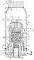
- An inflator 10 (Fig. 1) provides inflation fluid for inflating a vehicle occupant protection device, such as an air bag (not shown).
- the inflator 10 includes a generally cylindrical container 12 having a chamber 16 which holds a supply of stored gases.
- a cup shaped closure member 24 blocks gas flow from the chamber 16 through a plurality of discharge passages 28.
- the cup shaped closure member 24 has a closed end 24a and an opposite open end.
- a body 20 of combustible material is disposed in a housing 22.
- the body 20 of combustible material and the housing 22 extend into the cup shaped closure member 24.
- An igniter 32 is also disposed within the housing 22.
- the igniter 32 When an air bag is to be inflated, the igniter 32 is activated to ignite the body 20 of combustible material. Ignition of the body 20 of the combustible material creates heat and combustion products which apply pressure against the closed end 24a of the closure member 24. The pressure applied to the closed end 24a of the closure member 24 breaks the closure member and moves it away from the discharge passages 28, as shown in Fig. 4.
- the container 12 (Fig. 1) includes a cylindrical one-piece steel side wall 40.
- the side wall 40 has a longitudinal central axis which is coincident with a longitudinal central axis 42 of the container 12.
- the container 10 also includes a one-piece circular steel end wall 44 which is connected with the right end (as viewed in Fig. 1) of the side wall 40 at an annular weld 46.
- a fill passage 52 is formed in the end wall 44 and is closed by suitable means such as a steel ball 54 welded in place.
- the circular end wall 44 is coaxial with the side wall 40.
- the central axis 42 of the container 12 extends through the center of the end wall 44.
- a circular steel end wall 58 is connected with the left end (as viewed in Fig. 1) of the side wall 40 by an annular weld 60.
- the left end wall 58 is disposed in a coaxial relationship with the right end wall 44 and the side wall 40 of the container 12.
- the end wall 58 has parallel inner and outer, radially extending side surfaces 62 and 64.
- Inner side surface 62 is presented toward the interior of the container 12, while the outer side surface 64 is presented away from the interior of the container.
- the weld 60 connects the left end (as viewed in Fig. 1) of the side wall 40 with the end wall 58 at a location intermediate to the inner and outer side surfaces 62 and 64.
- the discharge passages 28 are formed in the end wall 58 and have cylindrical configurations with central axes which extend parallel to the central axis 42 of the container 12.
- the discharge passages 28 are arranged in an annular array about the central axis 42 of the container 12. Although only two discharge passages 28 are shown in Fig. 1, it should be understood that there are more than two discharge passages formed in the end wall 58. The number and arrangement of the discharge passages 28 can vary as desired.
- An annular metal foil seal 70 is secured by a suitable adhesive to the outer side surface 64 of the end wall 58 across the ends of each of the discharge passages 28.
- the seal 70 blocks the conduction of moisture from the environment around the inflator assembly 10 through the discharge passages 28.
- the housing 22 includes a tubular base section 74 (Fig. 2) which extends through the end wall 58 of the container 12.
- the base section 74 is generally circular in transverse section.
- An annular, radially extending shoulder 76 on the outer surface of the base section 74 abuts the inner side surface 62 of the end wall 58.
- An annular weld 80 connects the base section 74 of the housing 22 with the outer side surface 64 of the end wall 58.
- the base section 74 of the housing 22 has a cylindrical outer end portion 86 which extends axially outward, that is, away from the interior of the container 12 and toward the left as viewed in Fig. 2, from the end wall 58.
- An inner end portion 88 of the base section 74 extends axially inward, that is, toward the interior of the container 12 and to the right as viewed in Fig. 2, from the end wall 58.
- a cylindrical passage 90 extends through the center of the base section 74. The igniter 32 is located in the passage 90.
- a tubular main section 94 of the housing 22 is formed as one piece with the base section 74.
- the main section 94 of the housing 22 includes a cylindrical side wall 96.
- the side wall 96 and base section 74 have central axes which are coincident with the central axis 42 of the container 12.
- the cylindrical side wall 96 has a relatively large outer diameter. Therefore, the base section 74 flares radially outward to the side wall 96 of the main section 94 of the housing 22.
- the main section 94 of the housing 22 has a cylindrical housing chamber 98 (Fig. 2).
- the housing chamber 98 has a central axis which is coincident with the central axis 42 of the container 12.
- a retainer 116 is disposed within the chamber 98 adjacent to the body 20 of combustible material.
- a spiral spring 118 is disposed within the chamber 98 adjacent to the retainer 116 and on a side of the retainer opposite the body 20 of combustible material.
- a strainer 120 is disposed within the chamber 98 between the spring 118 and the closed end 24a of the closure member 24.
- the retainer 116 is a thin circular-shaped mesh of metallic wire. The retainer 116 is urged by the spring 118 against the body 20 of combustible material to maintain the body 20 of combustible material in a packed arrangement.
- the strainer 120 (Fig. 2) is preferably a powdered metal part.
- the strainer 120 has a flat, circular, radially extending inner side surface 124 which abuttingly engages one end of the spring 118 (Fig. 2).
- the strainer 120 also has cylindrical, axially extending side surface 126 which extends parallel to the central axis 42.
- the strainer 120 also has an annular, radially extending shoulder 127 on the cylindrical surface 126.
- the strainer 120 has a substantially circular outer side surface 128 which abuts the closed end 24a of the closure member 24.
- An annular crimp or rim 130 at the right end (as viewed in Fig. 2) of the cylindrical housing side wall 96 engages the shoulder 127 of the strainer 120 to hold the strainer in place in the housing 22.
- a plurality of passages are provided in the strainer 120 to conduct combustion products, including heat, which are created upon ignition of the body 20 of combustible material.
- the strainer 120 has four equally spaced cylindrical main passages 134 (two of which are shown in Fig. 2), which extend through the strainer 120.
- the passages 134 through the strainer 120 conduct combustion products from the body 20 of combustible material towards the closed end 24a of the closure member 24.
- the closure member 24 (Fig. 2) blocks gas flow from the chamber 16 through the discharge passages 28 and encloses the main section 94 of the housing 22.
- the closure member 24, as discussed above, has a generally cup shaped configuration and is formed as one piece of a suitable material, such as low carbon steel or annealed stainless steel.
- the closure member 24 has a central axis which is coincident with the central axis 42 of the container 12.
- the closure member 24 includes a skirt section 162 which is connected to the flat circular inner side surface 62 of the end wall 58 (Fig. 2).
- the closure member 24 has a cylindrical side wall 164 which is connected to and is coaxial with the skirt section 162.
- the side wall 164 encloses the main section 94 of the housing 22 and the body 20 of combustible material.
- An imperforate substantially circular end wall 166 of the closure member 24 is connected with the right end (as viewed in Fig. 2) portion of the side wall 164 and closes the end 24a of the cup shaped closure member.
- the end wall 166 extends across the right end (as viewed in Fig. 2) of the housing 22.
- the skirt section 162 has a side wall 170 with a configuration which is a frustrum of a cone.
- An annular flange 172 extends radially outward from the left (as viewed in Fig. 2) end of the side wall 170 and is connected to the end wall 58 by weld 163.
- the annular flange 172 circumscribes and is disposed in a coaxial relationship with the annular array of inlet openings to the discharge passages 28.
- the side wall 170 of the skirt section 162 extends from the main section 94 of the housing 22 to the inner side surface 62 of the end wall 58.
- the cylindrical main section 94 of the housing 22 has an outer surface which is located radially inward of the longitudinal axes of the individual discharge passages 28. Therefore, the skirt section 162 flares axially away and radially outward from the main section 94 of the housing 22 toward the end wall 58.
- the main section 94 of the housing 22 could be formed with a somewhat larger diameter so that the skirt section 162 could be cylindrical and still circumscribe the annular array of discharge passages 28.
- An annular frangible section 176 (Fig. 2) of reduced thickness is formed in the skirt section 162.
- the frangible section 176 is breakable under the influence of tension forces transmitted from the end wall 166 of the cup shaped closure member 24 upon ignition of the body 20 of combustible material.
- the frangible section 176 is coaxial with the central axis 42 of the container 12 and extends around the base section 74 of the housing 22.
- the skirt section 162 (Fig. 2) has an inner side surface 180 which cooperates with the inner side surface 62 on the end wall 58 and an outer side surface 181 of the base section 74 to form an annular manifold chamber 182.
- the manifold chamber 182 extends around the base section 74 of the housing 22 and has a central axis which is coincident with the central axis 42 of the container 12.
- the discharge passages 28 in the end wall 58 have circular inner ends which open to the manifold chamber 182.
- the manifold chamber 182 Prior to breaking of the frangible section 176 of the skirt section 162, the manifold chamber 182 is isolated from the supply of stored gas in the chamber 16. Thus, the fluid pressure in the manifold chamber 182, prior to breaking of the frangible section 176, will be approximately atmospheric pressure.
- the tubular side wall 164 (Fig. 2) of the closure member 24 has a cylindrical inner side surface 186 which is disposed in engagement with a cylindrical outer side surface of the main section 94 of the housing 22.
- the inner side surface 186 of the side wall 164 is freely slidable along the outside of the housing 22 under the influence of gas pressure applied against the end wall 166 after ignition of the body 20 of combustible material and breaking of the frangible section 176 of the closure member 24.
- the igniter 32 which is located in the passage 90 (Fig. 2) extending through the base section 74 of the housing 22, has a cylindrical configuration.
- the igniter 32 is axially aligned with the left end (as viewed in Fig. 2) of the body 20 of combustible material.
- An annular crimp or rim 194 at the left end (as viewed in Fig. 2) of the cylindrical outer end portion 86 of the base section 74 of the housing 22 engages an outer metal casing of the igniter 32 to hold the igniter in place in the housing 22.
- the igniter 32 includes a pyrotechnic charge which may be zirconium potassium perchlorate, titanium potassium perchlorate, or BKNO 3 or, if desired, a different chemical composition.
- the igniter 32 is connected with a sensor assembly (not shown) which detects vehicle deceleration. If the sensor assembly detects vehicle deceleration of a magnitude requiring actuation of an air bag to protect a vehicle occupant, the sensor assembly completes an electrical circuit with an energy source. Completing the electrical circuit actuates the igniter assembly 32 to effect ignition of the body 20 of combustible material.
- a one-piece seal cup 200 (Fig. 2) is disposed in the passage 90 and receives the igniter 32 to block the conduction of moisture to the body 20 of combustible material from the environment around the inflator assembly 10.
- the seal cup 200 is formed as a single piece of metal and has a thickness of between 0.20 and 0.30 millimeters.
- the seal cup 200 has an annular flange 202 which is connected with the outer or left (as viewed in Fig. 2) end of the base section 74 by the crimp 194.
- a plurality of score lines extend diametrically across the right (as viewed in Fig. 2) end wall 204 of the seal cup 200.
- the score lines have a depth of approximately 0.05 to 0.10 millimeters. The score lines weaken the seal cup 200 so that it is easily ruptured upon activation of the igniter 32.
- a diffuser 36 is formed from a single piece of steel and has a circular end wall 208 (Fig. 2).
- the diffuser end wall 208 is connected to the base section 74 of the housing 22 by an annular weld 210 and extends radially outward from the outer end portion 86 of the base section.
- the end wall 208 of the diffuser 36 has a central axis which is coincident with the central axis 42 of the container 12.
- a flat circular, radially extending inner side surface 212 on the end wall 208 extends parallel to and is spaced from the flat circular outer side surface 64 on the end wall 58.
- a cylindrical side wall 216 (Fig. 2) of the diffuser 36 is formed as one piece with the end wall 208 and extends axially from the outer periphery of the end wall 208.
- the outer diameter of the cylindrical side wall 216 of the diffuser 36 is essentially the same as the diameter of the outer side surface 64 on the end wall 58.
- the cylindrical side wall 216 of the diffuser 36 is connected to the outer side surface 64 of the container end wall 58 by weld 218.
- An annular array of radially extending cylindrical passages 220 is formed in the side wall 216 of the diffuser 36.
- the combined flow area of the passages 220 is larger than the combined flow area of the passages 28 in the end wall 58.
- the radially extending passages 220 are connected in fluid communication with an annular diffuser chamber 222 which is defined by the diffuser 36, the container end wall 58, and the base section 74 of the housing 22.
- the diffuser chamber 222 extends around the outer end portion 86 of the base section 74 of the housing 22.
- the diffuser passages 220 are also connected in fluid communication with the inside of an air bag (not shown).
- the housing 22, closure member 24, and diffuser 36 are all connected with the end wall 58 of the container 12. By connecting the housing 22, closure member 24 and diffuser 36 to the end wall 58, these components of the inflator assembly 10 can be mounted as a unit on the side wall 40 of the container.
- the igniter 32 can be connected to the housing 22 after the end wall 58, housing 22, closure member 24 and diffuser 36 have been connected as a unit with the side wall 40 of the container 12.
- the body 20 of combustible material comprises a plurality of randomly oriented cylindrical grains 100 disposed within the chamber 98 and part of the passage 90.
- Each of the grains 100 may be similar or identical in configuration.
- the configuration of a typical grain 100 is shown in detail in Fig. 3.
- the grain 100 has a cylindrical outer surface 102 centered on an axis 104.
- the grain 100 further has first and second opposite side surfaces 106 and 108.
- Each of the opposite side surfaces 106 and 108 has a circular shape centered on the axis 104, and is generally perpendicular to the axis 104.
- the grain 100 preferably has a cylindrical inner surface 110, which defines a respective cylindrical passage 112 extending axially through the grain 100.
- a cylindrical inner surface 110 which defines a respective cylindrical passage 112 extending axially through the grain 100.
- the grain 100 is shown in the preferred embodiment as having one passage 112, it is contemplated that the grain 100 may have a plurality of passages which may vary in arrangement and diameter. For instance, in addition to the cylindrical passage 112, the grain 100 may also have eighteen other passages extending through the grain.
- the body 20 of combustible material has been illustrated as being a plurality of randomly oriented cylindrical grains 100, it is contemplated that the body 20 of combustible material could be formed with a different configuration if desired.
- the body 20 of combustible material may have a multi-lobe cross-sectional configuration or may comprise a plurality of stacked cylinders.
- the body 20 of combustible material contains a quantity of a non-metallic nitrogen containing compound.
- the non-metallic nitrogen containing compound is a material capable of undergoing rapid and substantially complete oxidation.
- the preferred non-metallic nitrogen containing compound is a smokeless powder such as is used in the manufacture of explosives and ammunition.
- the non-metallic nitrogen containing compound may be a material utilized in a low vulnerability ammunition ("LOVA").
- the non-metallic nitrogen containing compound is preferably a material selected from the group consisting of nitroguanadine, triaminoguanadinenitrate, ethylene dinitramine, ethylenediamine dinitrate, 1, 3, 3-trinitroazetidine, cyclotrimethylenetrinitramine, cyclotetramethylenetetranitramine, trinitrotoluene, 2, 4, 6-trinitrophenylmethylnitramine and pentaerythritol tetranitrate and mixtures thereof.
- the non-metallic nitrogen containing compound is cyclotrimethylenetrinitramine (RDX).
- a second preferred non-metallic nitrogen containing compound is cyclotetramethylenetetranitramine (HMX).
- the non-metallic nitrogen containing compound is a solid at 20°C.
- the non-metallic nitrogen containing compound is present in the body 20 of combustible material in an amount of about 36% to about 76% by weight based on the weight of the body 20 of combustible material, excluding inert components.
- the non-metallic nitrogen containing compound is present in the body 20 of combustible material in an amount of about 50% by weight based on the weight of the body 20 of combustible material, excluding inert components.
- the body 20 of combustible material also includes a solid oxidizer material.
- the oxidizer enhances the combustion of the body 20 of combustible material and reduces the production of toxic gases such as carbon monoxide (CO), hydrogen cyanide (HCN), and oxides of nitrogen (NO x ).
- Suitable oxidizer materials include an alkali metal nitrate, alkali-earth metal nitrate, ammonium perchlorate, alkali metal perchlorate, alkali-earth metal perchlorate, organo-ammonium nitrate, or ammonium dinitramide.
- Suitable alkali metals include, but are not limited to, lithium, sodium, potassium, rubidium, and cesium.
- Suitable alkaline-earth metals include, but are not limited to, magnesium, calcium, strontium, and barium.
- Suitable organo-ammonium nitrates include, but are not limited to, tetramethylammonium nitrate, hydroxylammonium nitrate, and tetraalkylammonium nitrate.
- the oxidizer material is present in the body 20 of combustible material in an amount of about 1% to about 40% by weight based on the weight of the body 20 of combustible material, excluding inert components.
- the oxidizer material is present in the body 20 of combustible material in an amount of about 30% by weight based on the weight of the body 20 of combustible material, excluding inert components.
- the body 20 of combustible material also includes a thermoplastic polymer binder material which is mixed with the non-metallic nitrogen containing compound and the oxidizer material to provide an intimate mixture.
- the binder material is mixed with the non-metallic nitrogen containing compound and the oxidizer material to obtain a moldable or extrudable plastic mass.
- Suitable binder materials include cellulose acetate butyrate, cellulose acetate, polyester elastomers, polyether elastomers, polyurethanes, or copolymers of these polymers in any useful ratio.
- the thermoplastic polymer binder material is cellulose acetate butyrate.
- thermoplastic polymer binder material is present in the body 20 of combustible material in an amount of about 8% to about 22% by weight based on the weight of the body 20 of combustible material, excluding inert components.
- thermoplastic polymer binder material is present in the body 20 of combustible material in an amount of about 12% by weight based on the weight of the body 20 of combustible material, excluding inert components.
- the body 20 of combustible material may also include a non-energetic plasticizer.
- a non-energetic plasticizer typically employed in the manufacture of low vulnerability ammunition may be used.
- Suitable non-energetic plasticizers include, but are not limited to, tributylcitrate, acetyltriethylcitrate, aretyltributylcitrate, alkylcitrates, alkylesters, arylesters, and alkylarylesters.
- a non-energetic plasticizer it is desirable that the non-energetic plasticizer be tributylcitrate or acetyltriethylcitrate.
- the non-energetic plasticizer be present in the body 20 of combustible material in an amount of no more than about 12% by weight based on the weight of the body 20 of combustible material, excluding inert components.
- the non-energetic plasticizer is present in the body 20 of combusted material in an amount of about 7.6% by weight based on the weight of the body 20 of combustible material, excluding inert components.
- the body 20 of combustible material may also include an energetic plasticizer.
- Any energetic plasticizer typically employed in the manufacture of low vulnerability ammunition may be used.
- Suitable energetic plasticizers include, but are not limited to, glycidyl azide polymer, alkylnitratoethylnitramines (wherein the alkyl chain can be methyl, ethyl, propyl, or butyl), bis-nitropropylformal, and 1-5-diazido-3-nitrazapentane.
- the energetic plasticizer be present in the body 20 of combustible material in an amount of no more than about 12% by weight based on the weight of the body 20 of combustible material, excluding inert components.
- the body 20 of combustible material may also include a quantity of nitrocellulose (containing between 11% to 13.4% nitrogen) for use as a binder.
- nitrocellulose containing between 11% to 13.4% nitrogen
- the body 20 of combustible material may also include stabilizers to provide heat aging (service life) stability.
- Suitable stabilizers include ethyl centralite and n-methyl paranitroaniline.
- the stabilizer be present in the body 20 of combustible material in an amount of no more than about 4% by weight based on the weight of the body 20 of combustible material, excluding inert components.
- ethyl centralite is present in the body 20 of combustible material in an amount of about 0.4% based on the weight of the body 20 of combustible material, excluding inert compounds.
- the supply of gas is stored in the chamber 16 at a pressure of approximately 2,000 to 3,500 psi.
- the stored gas 30 is preferably stored in the container 16 at a pressure of approximately 1000 psi to about 5,000 psi, preferably about 3,000 psi to about 3,500 psi.
- the supply of stored gases in the chamber 16 comprises a mixture of one or more inert gases and at least one oxidizer gas.
- the preferred inert gases are helium (He) and argon (Ar).
- the inert gases comprise a mixture of argon and helium, with helium being present in an amount sufficient to act as a leak detector.
- the oxidizer gas is any gas capable of oxidizing the body 20 of combustible material and its combustion products to produce essentially non-toxic combustion products.
- the oxidizer gas is oxygen (O 2 ).
- the oxygen is preferably the only gas other than the inert gases present in the supply of stored gases.
- the stored gas comprises, on a weight basis, 10% to 25% oxygen, 1% to 5% helium, with the balance being argon.
- the most preferred composition of the stored gas is 75% argon, 20% oxygen, and 5% helium.
- the deceleration sensor assembly Upon the occurence of sudden vehicle deceleration of a magnitude requiring air bag inflation, the deceleration sensor assembly completes an electrical circuit to activate the igniter 32 (Fig. 2) in a known manner. This results in ignition of the pyrotechnic charge in the igniter 32. Burning of the pyrotechnic charge in the igniter 32 generates hot gas which ruptures the relatively thin seal cup 200.
- Rupturing the seal cup 200 enables hot gases from the burning ignition charge to flow through the passage 90 in the base section 74 of the housing 22.
- the hot gases engage the left end portion (as viewed in Fig. 2) of the body 20 of combustible material.
- the hot gases ignite the body 20 of combustible material to produce initial combustion products, including fundamental gases (i.e., carbon monoxide, carbon dioxide (CO 2 ), water (H 2 O), hydrogen cyanide, oxides of nitrogen, formaldehyde (HCOH), Methane (CH 4 ), etc.) and a first quantity of heat.
- fundamental gases i.e., carbon monoxide, carbon dioxide (CO 2 ), water (H 2 O), hydrogen cyanide, oxides of nitrogen, formaldehyde (HCOH), Methane (CH 4 ), etc.
- the initial combustion products are conducted through the strainer 120 of the housing 22.
- the initial combustion products apply pressure against the end wall 166 of the closure member 24.
- the pressure applied against the end wall 166 of the closure member 24 results in the transmission of tensile forces through the side wall 164 of the closure member to the skirt section 162 of the closure member. These tensile forces are effective to break the frangible section 176 (Fig. 2) of the skirt section 162.
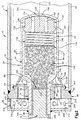
- the pressure applied by the initial combustion products from the burning body 20 of combustible material moves the closure member 24 away from the end wall 58 of the container 12 toward the opposite end wall 44 (see Fig. 4).
- the pressure applied against the end wall 166 (Fig. 2) of the closure member 24 moves the closure member toward the right (as viewed in Fig. 2).
- This movement of the closure member 24 is initially guided by sliding movement of the side wall 164 of the closure member along the side wall 96 of the housing 22.
- the closure member 24 then separates from the housing 22 and comes to rest adjacent to the end wall 44 of the container 12 (Fig. 4).
- the strainer 120, the spring 118, and the retainer 116 are retained in the housing 22 by the crimp 130.
- the initial combustion products from the body 20 of combustible material mix with and heat the stored gases in the chamber 16.
- Any partially combusted initial combustion products (i.e, carbon monoxide, hydrogen cyanide, etc.) of the combustible material 20 further combust in the presence of the oxidizer gas to form an essentially non-toxic subsequent combustion product and a second quantity of heat.
- the first quantity of heat and the second quantity of heat increase the temperature of the supply of stored gases in the chamber 16, including the inert gas.
- An air bag inflation fluid comprising the heated inert gas, the combustion products, and any remaining heated oxidizer gas flows into the annular manifold chamber 182.
- the pressure from the inflation fluid transmitted from the manifold chamber 182 through the discharge passages 28 ruptures the seal 70 (Figs. 2 and 4).
- the inflation fluid then flows from the chamber 16 through the discharge openings 28 into the diffuser chamber 222.
- the inflation fluid When the inflation fluid enters the diffuser chamber 222, it impinges against the end wall 208 of the diffuser 36.
- the end wall 208 of the diffuser 36 directs the inflation fluid flow radially outward toward the openings 220 in the side wall 216 of the diffuser 36.
- the inflation fluid flows through the openings 220 to the air bag.
- the openings 28 and the diffuser 36 thus comprise a conduit for directing the inflation fluid into the air bag.
- the air bag is thus inflated to the desired volume by the inflation fluid.
- An advantage to using the quantity of non-metallic nitrogen containing compound to generate heat is that metallic by-products are not produced.
- the combustion products produced by the ignition of the non-metallic nitrogen containing compound are relatively smokeless.
- the inflator 10 does not require a filter.
- the inert gases have relatively low specific heats.
- the inert gases are also non-reactive when heated by the ignited non-metallic nitrogen containing compound.
- An advantage to having a quantity of a solid oxidizer material in the body 20 of combustible material in combination with a quantity of oxygen gas stored in the chamber 16 is that the body 20 of combustible material can undergo substantially complete combustion, producing an inflation fluid essentially free of harmful levels of toxic gases.
- the solid oxidizer material in the body 20 of combustible material ensures an initial combustion of the body 20 of combustible material in the chamber 98 which produces a gaseous combustion product consisting essentially of fundamental gases instead of larger organic molecules.
- the oxidizer gas in the chamber 16 is necessary to combust further the partially combusted fundamental gases, including the toxic gases, to stable non-toxic gases. It is believed that the hydrogen cyanide further combusts in the presence of the oxidizer gas to nitrogen (N 2 ) and carbon dioxide. It is believed that some of the nitric oxide (NO) further combusts in the presence of the oxidizer gas to nitrogen and oxygen. It is believed that some of the nitric oxide further combusts in the presence of the carbon monoxide gas to nitrogen and carbon dioxide. It is believed that some of the nitrogen dioxide (NO 2 ) further combusts in the presence of the oxidizer gas to nitrogen and oxygen. It is believed that some of the nitrogen dioxide further combusts in the presence of the carbon monoxide gas to nitrogen and carbon dioxide. It is believed that the methane further combusts in the presence of the oxidizer gas to carbon dioxide and water.
- a prior art composition of an inflator propellant is designated M-39 LOVA and is also summarized below in Table 1.
- M-39 LOVA is also summarized below in Table 1.
- Table 1 Also summarized below in Table 1 are (i) the oxygen produced by each of the propellants in (a) moles, and (b) grams, and (ii) the % reduction in oxygen required to complete combustion of the propellants of the present invention as compared to the amount of oxygen required to complete combustion of the M-39 LOVA propellant.
- the prior art propellant M-39 LOVA does not have any oxidizer material and thus, does not produce any oxygen when combusted. As such, the M-39 LOVA propellant requires a substantial amount of oxygen gas to be present to combust completely.
- Each of the OML 1 through OML 16 propellants has between 10% to 30% of an oxidizer material (i.e., potassium perchlorate, potassium nitrate, or ammonium perchlorate).
- the oxidizer materials produce between 9.57 millimoles (0.306 grams) to 38.96 millimoles (1.247 grams) of oxygen. This results in an 8% to 32.4% reduction in oxygen required for the propellants of the present invention to combust completely as compared to the amount of oxygen required to combust completely the M-39 LOVA propellant. This reduction in oxygen can reduce the amount (i.e., volume) of stored oxygen in the container, thus resulting in a smaller, lighter and more economical inflator.
- OML 3 A comparison of OML 3, OML 5, and OML 8 illustrates that potassium perchlorate produces more oxygen per quantity than either potassium nitrate or ammonium perchlorate.
- potassium perchlorate is the preferred solid oxidizer material of the present invention.
- the burn rates and ignition times of the OML 13 propellant of the present invention and prior art propellants were measured in a 200 cubic centimeter (cc) closed bomb.
- the closed bomb contains ambient air at atmospheric pressure.
- Each of the propellants tested weighed 10 grams.
- the OMLOVA-20% AN (ammonium nitrate) propellant comprises on a weight basis 56% RDX, 12% CAB, 7.6% TBC or ATEC, 4% NC, 0.4% EC and 20% AN (ammonium nitrate).
- the OMLOVA-10% AN (ammonium nitrate) propellant comprises on a weight basis 66% RDX, 12% CAB, 7.6% TBC or ATEC, 4% NC, 0.4% EC and 10% AN.
- the OML 13 propellant was ignited with 1 gram of black powder.
- the prior art propellants each required 2 grams of black powder to be ignited.
- a 1 gram black powder igniter charge could not reliably ignite the prior art propellants.
- the ignition time of each of the propellants was measured in milliseconds.
- the ignition time is the time required for the propellant to produce a pressure in the bomb of 6.9 MPa.
- the burn rate of each of the propellants was measured in centimeters per second at pressures of 24 MPa and 32 MPa. The results of the test are summarized below in Table II.
- the ignition time for the OMLOVA-20% AN and OMLOVA-10% AN propellants are almost twice as long as the ignition time of the propellant of the present invention.
- the pressure inside the closed bomb at different times are plotted in Fig. 5.
- the ignition times for the prior art ammonium nitrate propellants are too high for practical application in an air bag inflator.
- the prior art ammonium nitrate propellants also required an igniter charge which is twice as big as the igniter charge for the OML 13 propellant of the present invention.
- the burn rates of the prior art ammonium nitrate propellants are too slow for practical application in an air bag inflator.
- the burn rate at 24 MPa for the OML 13 propellant of the present invention is about 2.3 times faster than the OMLOVA-20% AN propellant and about 3.6 times faster than the OMLOVA-10% AN propellant.
- the burn rate at 32 MPa for the OML 13 propellant of the present invention is about 2.9 times faster than the OMLOVA-20% AN propellant and about 3.8 times faster than the OMLOVA-10% AN propellant.
- the burn rates of the OML 13 propellant and the OMLOVA-20% AN propellant at different pressures in the closed bomb are plotted in Fig. 6.
- the toxic effluent gases produced upon combustion of two different prior art propellants and propellants of the present invention were also measured in parts per million in a 60 liter tank test.
- the composition of each of the propellants tested can be found in Table I with the exception of the GAP LOVA propellant.
- the GAP LOVA propellant comprises on a weight basis 76% RDX, 12% CAB, and 12% GAP (glycidyl azide polymer).
- Each of the propellants tested were fired in an inflator having a configuration similar to that of Fig. 1 and filled with a gas having a composition, on a weight basis, of about 75% argon, about 20% oxygen and about 5% helium and stored at a pressure of about 3500 psi.
- the gases produced upon combustion of the propellants were allowed to flow into a 60 liter tank and were measured.
- the results of the 60 liter tank test are summarized below in Table III. Also illustrated in Table III is a standard automobile manufacturer's passenger specification for the 60 liter tank test in parts per million and the lethal concentration (LC) 50 levels for a vehicle occupant exposed to the listed gases in a standard sized vehicle compartment for at least 30 minutes.
- LC lethal concentration
- the M-39 LOVA and the GAP LOVA propellants produced carbon monoxide levels at least 6.5 to 11 times higher, and at least 3 to 5 times higher, respectively, than the levels produced by the propellants of the present invention.
- the M-39 LOVA and the GAP LOVA propellants also produced hydrogen cyanide (HCN) levels at least 21 to 76 times higher, and at least 11 to 40 times higher, respectively, than the levels produced by the propellants of the present invention.
- HCN hydrogen cyanide
- the M-39 LOVA and the GAP LOVA propellants also produced formaldehyde levels at least 8 to 16 times higher, and at least 2 to 4 times higher, respectively, than the levels produced by the propellants of the present invention.
- the M-39 LOVA and the GAP LOVA propellants produced nitrogen dioxide levels at least 2.4 to 7 times higher, and at. least 1.2 to 3.4 times higher, respectively, than the levels produced by the propellants of the present invention.
- the M-39 LOVA and the GAP LOVA propellants both produced nitrogen dioxide levels in excess of the LC 50 level. All of the propellants of the present invention produced effluent gas levels lower than the LC 50 level for all of the effluent gases tested.
- the toxic effluent gas levels from low fill pressure inflators loaded with OML 2, M-39 LOVA and GAP LOVA propellants were measured in a 100 cubic foot: tank test.
- the 100 cubic foot tank is essentially equivalent: to the size of a standard automobile passenger compartment.
- Each of the propellants tested was fired in an inflator having a configuration similar to that of Fig. 1 and filled with a gas having a composition, on a weight basis, of about 75% argon, about 20% oxygen and about 5% helium and stored at a pressure of about 1,000 psi. This is significantly less than the typical pressure of an air bag inflator, which is about 3,500 psi.
- a pressure of about 1,000 psi is illustrative of the pressure inside an air bag inflator with a gas leak.
- An inflator at a pressure of about 1,000 psi because of the lower pressure and smaller amount of oxygen, does not support combustion of a propellant as well as an inflator at higher pressures.
- the 100 cubic foot tank test shows the effects of incomplete combustion in a prior art LOVA type gas generating propellant and propellants of the present invention in an inflator with less than ideal pressure.
- Table IV Also illustrated in Table IV is a standard automobile manufacturer's passenger specification at typical pressures (i.e., 3500 psi) for the 100 cubic foot tank test in parts per million.
- the OML2 propellant produced lower levels per gram of propellant of nitric oxide, nitrogen dioxide, hydrogen cyanide than the M-39 LOVA and the GAP LOVA propellants. Moreover, the OML2 propellant produced lower levels per gram of propellant of carbon monoxide and formaldehyde than the M-39 propellant. Also, as can be seen in Table IV, the OML2 propellant produced, on a per gram basis, levels of carbon monoxide and formaldehyde equal to the GAP LOVA propellant.
- the OML 2 propellant produced levels of nitric oxide, nitrogen dioxide, hydrogen cyanide, and formaldehyde within the industry standard for effluents produced in an inflator fired at 3500 psi.
- the propellants of the present invention produce more oxygen than the prior art propellants, and thus require less stored oxygen to combust completely.
- the propellants of the present invention also have significantly improved burn rates in comparison to prior art propellants.
- the shock wave output of propellants of the present invention and prior art M-39 propellant were compared in the TNT equivalency test.
- the propellants of the present invention produced a shock wave output which was about 50% of the shock wave output produced by the prior art M-39 propellant.
- the propellants of the present invention when fired in an inflator of the present invention, has improved toxic effluent levels in comparison to the prior art inflators.
Description
- The present invention relates to a hybrid inflator for inflating a vehicle occupant protection device.
- A hybrid inflator for inflating a vehicle occupant protection device includes a quantity of a stored gas and a body of combustible material. The stored gas typically comprises an inert gas and an oxidizer gas. The oxidizer gas helps to support the combustion of the body of combustible material. An igniter is actuatable to ignite the body of combustible material. As the body of combustible material burns, combustion products heat the inert gas. This increases the pressure of the inert gas. The heated inert gas and the combustion products form the inflation fluid.
- Further attention is drawn to EP-A-0 673 809 that forms the closest prior art and deals with a hybrid inflator for an automotive inflatable safety system. The inflator includes in one embodiment a stored gas housing and a gas generator housing. Propellant grains are contained within the gas generator and an appropriate pressurized medium consisting essentially of an inert fluid and oxygen is contained within the stored gas housing. Generally, the pressurized medium flows through the gas generator or an extension thereof when exiting the inflator to the air/safety bag to enhance the mixing and reaction of the pressurised medium with the propellant gases. The hybrid inflator may utilise a gun-typ propellant as the formulation for the propellant grains and a mixture of at least one inert gas and oxygen for the pressurised medium.
- In accordance with the present invention an apparatus for use in inflating a vehicle occupant protection device as set forth in claim 1 and a method for inflating a vehicle occupant protection device as set forth in claim 9 are provided. Preferred embodiments are disclosed in the dependent claims.
- The present invention relates to an apparatus for use in inflating a vehicle occupant protection device. The apparatus comprises a container, a supply of gas stored in the container, a combustible material, and igniter means for igniting the combustible material. The stored gas comprises an inert gas and an oxidizer gas. The combustible material comprises (a) a non-metallic nitrogen containing compound, (b) a thermoplastic polymer, and (c) an oxidizer selected from the group consisting of an alkali metal nitrate, alkali-earth metal nitrate, ammonium perchlorate, alkali metal perchlorate, alkali-earth metal perchlorate, organo-ammonium nitrate, and ammonium dinitramide. The combustible material, when ignited, burns in the presence of the oxidizer gas and generates combustion products including heat for heating the inert gas. The apparatus further comprises a conduit for directing the heated inert gas and the combustion products toward the vehicle occupant protection device.
- The foregoing and other objects and features of the present invention will become more apparent to one skilled in the art upon a consideration of the following description of the invention and the accompanying drawings in which:
- Fig. 1 is a sectional view of an inflator constructed in accordance with the present invention;
- Fig. 2 is an enlarged fragmentary sectional view of a portion of the inflator of Fig. 1;
- Fig. 3 is an enlarged view of a part in Fig. 1;
- Fig. 4 is a sectional view, generally similar to Fig. 1, illustrating the relationship between parts of the inflator of Fig. 1 after the inflator has been actuated;
- Fig. 5 is a graph showing the rate of increase in pressure resulting from combustion of a propellant of the present invention and two prior art propellants; and
- Fig. 6 is a graph showing the burn rate at differing pressures of a propellant of the present invention and a prior art propellant.
-
- An inflator 10 (Fig. 1) provides inflation fluid for inflating a vehicle occupant protection device, such as an air bag (not shown). The
inflator 10 includes a generallycylindrical container 12 having achamber 16 which holds a supply of stored gases. - A cup shaped
closure member 24 blocks gas flow from thechamber 16 through a plurality ofdischarge passages 28. The cup shapedclosure member 24 has a closedend 24a and an opposite open end. Abody 20 of combustible material is disposed in ahousing 22. Thebody 20 of combustible material and thehousing 22 extend into the cupshaped closure member 24. Anigniter 32 is also disposed within thehousing 22. - When an air bag is to be inflated, the
igniter 32 is activated to ignite thebody 20 of combustible material. Ignition of thebody 20 of the combustible material creates heat and combustion products which apply pressure against the closedend 24a of theclosure member 24. The pressure applied to the closedend 24a of theclosure member 24 breaks the closure member and moves it away from thedischarge passages 28, as shown in Fig. 4. - The container 12 (Fig. 1) includes a cylindrical one-piece
steel side wall 40. Theside wall 40 has a longitudinal central axis which is coincident with a longitudinalcentral axis 42 of thecontainer 12. Thecontainer 10 also includes a one-piece circularsteel end wall 44 which is connected with the right end (as viewed in Fig. 1) of theside wall 40 at anannular weld 46. Afill passage 52 is formed in theend wall 44 and is closed by suitable means such as asteel ball 54 welded in place. Thecircular end wall 44 is coaxial with theside wall 40. Thecentral axis 42 of thecontainer 12 extends through the center of theend wall 44. - A circular
steel end wall 58 is connected with the left end (as viewed in Fig. 1) of theside wall 40 by anannular weld 60. Theleft end wall 58 is disposed in a coaxial relationship with theright end wall 44 and theside wall 40 of thecontainer 12. Theend wall 58 has parallel inner and outer, radially extendingside surfaces Inner side surface 62 is presented toward the interior of thecontainer 12, while theouter side surface 64 is presented away from the interior of the container. Theweld 60 connects the left end (as viewed in Fig. 1) of theside wall 40 with theend wall 58 at a location intermediate to the inner andouter side surfaces - The
discharge passages 28 are formed in theend wall 58 and have cylindrical configurations with central axes which extend parallel to thecentral axis 42 of thecontainer 12. Thedischarge passages 28 are arranged in an annular array about thecentral axis 42 of thecontainer 12. Although only twodischarge passages 28 are shown in Fig. 1, it should be understood that there are more than two discharge passages formed in theend wall 58. The number and arrangement of thedischarge passages 28 can vary as desired. - An annular
metal foil seal 70 is secured by a suitable adhesive to theouter side surface 64 of theend wall 58 across the ends of each of thedischarge passages 28. Theseal 70 blocks the conduction of moisture from the environment around theinflator assembly 10 through thedischarge passages 28. - The
housing 22, which encloses thebody 20 of combustible material, has a central axis which is coincident with thecentral axis 42 of thecontainer 12. Thehousing 22 includes a tubular base section 74 (Fig. 2) which extends through theend wall 58 of thecontainer 12. Thebase section 74 is generally circular in transverse section. An annular, radially extendingshoulder 76 on the outer surface of thebase section 74 abuts theinner side surface 62 of theend wall 58. Anannular weld 80 connects thebase section 74 of thehousing 22 with theouter side surface 64 of theend wall 58. - The
base section 74 of thehousing 22 has a cylindricalouter end portion 86 which extends axially outward, that is, away from the interior of thecontainer 12 and toward the left as viewed in Fig. 2, from theend wall 58. Aninner end portion 88 of thebase section 74 extends axially inward, that is, toward the interior of thecontainer 12 and to the right as viewed in Fig. 2, from theend wall 58. Acylindrical passage 90 extends through the center of thebase section 74. Theigniter 32 is located in thepassage 90. - A tubular
main section 94 of thehousing 22 is formed as one piece with thebase section 74. Themain section 94 of thehousing 22 includes acylindrical side wall 96. Theside wall 96 andbase section 74 have central axes which are coincident with thecentral axis 42 of thecontainer 12. Thecylindrical side wall 96 has a relatively large outer diameter. Therefore, thebase section 74 flares radially outward to theside wall 96 of themain section 94 of thehousing 22. - The
main section 94 of thehousing 22 has a cylindrical housing chamber 98 (Fig. 2). Thehousing chamber 98 has a central axis which is coincident with thecentral axis 42 of thecontainer 12. - A
retainer 116 is disposed within thechamber 98 adjacent to thebody 20 of combustible material. Aspiral spring 118 is disposed within thechamber 98 adjacent to theretainer 116 and on a side of the retainer opposite thebody 20 of combustible material. Astrainer 120 is disposed within thechamber 98 between thespring 118 and theclosed end 24a of theclosure member 24. Theretainer 116 is a thin circular-shaped mesh of metallic wire. Theretainer 116 is urged by thespring 118 against thebody 20 of combustible material to maintain thebody 20 of combustible material in a packed arrangement. - The strainer 120 (Fig. 2) is preferably a powdered metal part. The
strainer 120 has a flat, circular, radially extendinginner side surface 124 which abuttingly engages one end of the spring 118 (Fig. 2). Thestrainer 120 also has cylindrical, axially extendingside surface 126 which extends parallel to thecentral axis 42. Thestrainer 120 also has an annular, radially extendingshoulder 127 on thecylindrical surface 126. Thestrainer 120 has a substantially circularouter side surface 128 which abuts theclosed end 24a of theclosure member 24. An annular crimp or rim 130 at the right end (as viewed in Fig. 2) of the cylindricalhousing side wall 96 engages theshoulder 127 of thestrainer 120 to hold the strainer in place in thehousing 22. - A plurality of passages are provided in the
strainer 120 to conduct combustion products, including heat, which are created upon ignition of thebody 20 of combustible material. Specifically, thestrainer 120 has four equally spaced cylindrical main passages 134 (two of which are shown in Fig. 2), which extend through thestrainer 120. Thepassages 134 through thestrainer 120 conduct combustion products from thebody 20 of combustible material towards theclosed end 24a of theclosure member 24. - The closure member 24 (Fig. 2) blocks gas flow from the
chamber 16 through thedischarge passages 28 and encloses themain section 94 of thehousing 22. Theclosure member 24, as discussed above, has a generally cup shaped configuration and is formed as one piece of a suitable material, such as low carbon steel or annealed stainless steel. Theclosure member 24 has a central axis which is coincident with thecentral axis 42 of thecontainer 12. - The
closure member 24 includes askirt section 162 which is connected to the flat circularinner side surface 62 of the end wall 58 (Fig. 2). Theclosure member 24 has acylindrical side wall 164 which is connected to and is coaxial with theskirt section 162. Theside wall 164 encloses themain section 94 of thehousing 22 and thebody 20 of combustible material. An imperforate substantiallycircular end wall 166 of theclosure member 24 is connected with the right end (as viewed in Fig. 2) portion of theside wall 164 and closes theend 24a of the cup shaped closure member. Theend wall 166 extends across the right end (as viewed in Fig. 2) of thehousing 22. - The
skirt section 162 has aside wall 170 with a configuration which is a frustrum of a cone. Anannular flange 172 extends radially outward from the left (as viewed in Fig. 2) end of theside wall 170 and is connected to theend wall 58 byweld 163. Theannular flange 172 circumscribes and is disposed in a coaxial relationship with the annular array of inlet openings to thedischarge passages 28. - The
side wall 170 of theskirt section 162 extends from themain section 94 of thehousing 22 to theinner side surface 62 of theend wall 58. In the embodiment of the invention illustrated in Fig. 2, the cylindricalmain section 94 of thehousing 22 has an outer surface which is located radially inward of the longitudinal axes of theindividual discharge passages 28. Therefore, theskirt section 162 flares axially away and radially outward from themain section 94 of thehousing 22 toward theend wall 58. However, it is contemplated that themain section 94 of thehousing 22 could be formed with a somewhat larger diameter so that theskirt section 162 could be cylindrical and still circumscribe the annular array ofdischarge passages 28. - An annular frangible section 176 (Fig. 2) of reduced thickness is formed in the
skirt section 162. Thefrangible section 176 is breakable under the influence of tension forces transmitted from theend wall 166 of the cup shapedclosure member 24 upon ignition of thebody 20 of combustible material. Thefrangible section 176 is coaxial with thecentral axis 42 of thecontainer 12 and extends around thebase section 74 of thehousing 22. - The skirt section 162 (Fig. 2) has an inner side surface 180 which cooperates with the
inner side surface 62 on theend wall 58 and anouter side surface 181 of thebase section 74 to form anannular manifold chamber 182. Themanifold chamber 182 extends around thebase section 74 of thehousing 22 and has a central axis which is coincident with thecentral axis 42 of thecontainer 12. Thedischarge passages 28 in theend wall 58 have circular inner ends which open to themanifold chamber 182. - Prior to breaking of the
frangible section 176 of theskirt section 162, themanifold chamber 182 is isolated from the supply of stored gas in thechamber 16. Thus, the fluid pressure in themanifold chamber 182, prior to breaking of thefrangible section 176, will be approximately atmospheric pressure. - The tubular side wall 164 (Fig. 2) of the
closure member 24 has a cylindricalinner side surface 186 which is disposed in engagement with a cylindrical outer side surface of themain section 94 of thehousing 22. Theinner side surface 186 of theside wall 164 is freely slidable along the outside of thehousing 22 under the influence of gas pressure applied against theend wall 166 after ignition of thebody 20 of combustible material and breaking of thefrangible section 176 of theclosure member 24. - The
igniter 32, which is located in the passage 90 (Fig. 2) extending through thebase section 74 of thehousing 22, has a cylindrical configuration. Theigniter 32 is axially aligned with the left end (as viewed in Fig. 2) of thebody 20 of combustible material. An annular crimp or rim 194 at the left end (as viewed in Fig. 2) of the cylindricalouter end portion 86 of thebase section 74 of thehousing 22 engages an outer metal casing of theigniter 32 to hold the igniter in place in thehousing 22. Theigniter 32 includes a pyrotechnic charge which may be zirconium potassium perchlorate, titanium potassium perchlorate, or BKNO3 or, if desired, a different chemical composition. - The
igniter 32 is connected with a sensor assembly (not shown) which detects vehicle deceleration. If the sensor assembly detects vehicle deceleration of a magnitude requiring actuation of an air bag to protect a vehicle occupant, the sensor assembly completes an electrical circuit with an energy source. Completing the electrical circuit actuates theigniter assembly 32 to effect ignition of thebody 20 of combustible material. - A one-piece seal cup 200 (Fig. 2) is disposed in the
passage 90 and receives theigniter 32 to block the conduction of moisture to thebody 20 of combustible material from the environment around theinflator assembly 10. Theseal cup 200 is formed as a single piece of metal and has a thickness of between 0.20 and 0.30 millimeters. Theseal cup 200 has anannular flange 202 which is connected with the outer or left (as viewed in Fig. 2) end of thebase section 74 by thecrimp 194. A plurality of score lines (not shown) extend diametrically across the right (as viewed in Fig. 2)end wall 204 of theseal cup 200. The score lines have a depth of approximately 0.05 to 0.10 millimeters. The score lines weaken theseal cup 200 so that it is easily ruptured upon activation of theigniter 32. - A
diffuser 36 is formed from a single piece of steel and has a circular end wall 208 (Fig. 2). Thediffuser end wall 208 is connected to thebase section 74 of thehousing 22 by anannular weld 210 and extends radially outward from theouter end portion 86 of the base section. Theend wall 208 of thediffuser 36 has a central axis which is coincident with thecentral axis 42 of thecontainer 12. A flat circular, radially extendinginner side surface 212 on theend wall 208 extends parallel to and is spaced from the flat circularouter side surface 64 on theend wall 58. - A cylindrical side wall 216 (Fig. 2) of the
diffuser 36 is formed as one piece with theend wall 208 and extends axially from the outer periphery of theend wall 208. The outer diameter of thecylindrical side wall 216 of thediffuser 36 is essentially the same as the diameter of theouter side surface 64 on theend wall 58. Thecylindrical side wall 216 of thediffuser 36 is connected to theouter side surface 64 of thecontainer end wall 58 byweld 218. - An annular array of radially extending
cylindrical passages 220 is formed in theside wall 216 of thediffuser 36. The combined flow area of thepassages 220 is larger than the combined flow area of thepassages 28 in theend wall 58. Theradially extending passages 220 are connected in fluid communication with anannular diffuser chamber 222 which is defined by thediffuser 36, thecontainer end wall 58, and thebase section 74 of thehousing 22. Thediffuser chamber 222 extends around theouter end portion 86 of thebase section 74 of thehousing 22. Thediffuser passages 220 are also connected in fluid communication with the inside of an air bag (not shown). - The
housing 22,closure member 24, anddiffuser 36 are all connected with theend wall 58 of thecontainer 12. By connecting thehousing 22,closure member 24 anddiffuser 36 to theend wall 58, these components of theinflator assembly 10 can be mounted as a unit on theside wall 40 of the container. Theigniter 32 can be connected to thehousing 22 after theend wall 58,housing 22,closure member 24 anddiffuser 36 have been connected as a unit with theside wall 40 of thecontainer 12. - In a preferred embodiment, the
body 20 of combustible material comprises a plurality of randomly orientedcylindrical grains 100 disposed within thechamber 98 and part of thepassage 90. Each of thegrains 100 may be similar or identical in configuration. - The configuration of a
typical grain 100 is shown in detail in Fig. 3. Thegrain 100 has a cylindricalouter surface 102 centered on anaxis 104. Thegrain 100 further has first and second opposite side surfaces 106 and 108. Each of the opposite side surfaces 106 and 108 has a circular shape centered on theaxis 104, and is generally perpendicular to theaxis 104. - The
grain 100 preferably has a cylindricalinner surface 110, which defines a respectivecylindrical passage 112 extending axially through thegrain 100. Although thegrain 100 is shown in the preferred embodiment as having onepassage 112, it is contemplated that thegrain 100 may have a plurality of passages which may vary in arrangement and diameter. For instance, in addition to thecylindrical passage 112, thegrain 100 may also have eighteen other passages extending through the grain. - Although the
body 20 of combustible material has been illustrated as being a plurality of randomly orientedcylindrical grains 100, it is contemplated that thebody 20 of combustible material could be formed with a different configuration if desired. For instance, thebody 20 of combustible material may have a multi-lobe cross-sectional configuration or may comprise a plurality of stacked cylinders. - The
body 20 of combustible material contains a quantity of a non-metallic nitrogen containing compound. The non-metallic nitrogen containing compound is a material capable of undergoing rapid and substantially complete oxidation. The preferred non-metallic nitrogen containing compound is a smokeless powder such as is used in the manufacture of explosives and ammunition. The non-metallic nitrogen containing compound may be a material utilized in a low vulnerability ammunition ("LOVA"). - The non-metallic nitrogen containing compound is preferably a material selected from the group consisting of nitroguanadine, triaminoguanadinenitrate, ethylene dinitramine, ethylenediamine dinitrate, 1, 3, 3-trinitroazetidine, cyclotrimethylenetrinitramine, cyclotetramethylenetetranitramine, trinitrotoluene, 2, 4, 6-trinitrophenylmethylnitramine and pentaerythritol tetranitrate and mixtures thereof. Preferably, the non-metallic nitrogen containing compound is cyclotrimethylenetrinitramine (RDX). A second preferred non-metallic nitrogen containing compound is cyclotetramethylenetetranitramine (HMX). The non-metallic nitrogen containing compound is a solid at 20°C.
- The non-metallic nitrogen containing compound is present in the
body 20 of combustible material in an amount of about 36% to about 76% by weight based on the weight of thebody 20 of combustible material, excluding inert components. Preferably, the non-metallic nitrogen containing compound is present in thebody 20 of combustible material in an amount of about 50% by weight based on the weight of thebody 20 of combustible material, excluding inert components. - The
body 20 of combustible material also includes a solid oxidizer material. The oxidizer enhances the combustion of thebody 20 of combustible material and reduces the production of toxic gases such as carbon monoxide (CO), hydrogen cyanide (HCN), and oxides of nitrogen (NOx). Suitable oxidizer materials include an alkali metal nitrate, alkali-earth metal nitrate, ammonium perchlorate, alkali metal perchlorate, alkali-earth metal perchlorate, organo-ammonium nitrate, or ammonium dinitramide. Suitable alkali metals include, but are not limited to, lithium, sodium, potassium, rubidium, and cesium. Suitable alkaline-earth metals include, but are not limited to, magnesium, calcium, strontium, and barium. Suitable organo-ammonium nitrates include, but are not limited to, tetramethylammonium nitrate, hydroxylammonium nitrate, and tetraalkylammonium nitrate. - The oxidizer material is present in the
body 20 of combustible material in an amount of about 1% to about 40% by weight based on the weight of thebody 20 of combustible material, excluding inert components. Preferably, the oxidizer material is present in thebody 20 of combustible material in an amount of about 30% by weight based on the weight of thebody 20 of combustible material, excluding inert components. - The
body 20 of combustible material also includes a thermoplastic polymer binder material which is mixed with the non-metallic nitrogen containing compound and the oxidizer material to provide an intimate mixture. The binder material is mixed with the non-metallic nitrogen containing compound and the oxidizer material to obtain a moldable or extrudable plastic mass. - Suitable binder materials include cellulose acetate butyrate, cellulose acetate, polyester elastomers, polyether elastomers, polyurethanes, or copolymers of these polymers in any useful ratio. Preferably, the thermoplastic polymer binder material is cellulose acetate butyrate.
- The thermoplastic polymer binder material is present in the
body 20 of combustible material in an amount of about 8% to about 22% by weight based on the weight of thebody 20 of combustible material, excluding inert components. Preferably, the thermoplastic polymer binder material is present in thebody 20 of combustible material in an amount of about 12% by weight based on the weight of thebody 20 of combustible material, excluding inert components. - The
body 20 of combustible material may also include a non-energetic plasticizer. Any non-energetic plasticizer typically employed in the manufacture of low vulnerability ammunition may be used. Suitable non-energetic plasticizers include, but are not limited to, tributylcitrate, acetyltriethylcitrate, aretyltributylcitrate, alkylcitrates, alkylesters, arylesters, and alkylarylesters. Preferably, when a non-energetic plasticizer is used, it is desirable that the non-energetic plasticizer be tributylcitrate or acetyltriethylcitrate. - When a non-energetic plasticizer is used, it is further desirable that the non-energetic plasticizer be present in the
body 20 of combustible material in an amount of no more than about 12% by weight based on the weight of thebody 20 of combustible material, excluding inert components. Preferably, the non-energetic plasticizer is present in thebody 20 of combusted material in an amount of about 7.6% by weight based on the weight of thebody 20 of combustible material, excluding inert components. - The
body 20 of combustible material may also include an energetic plasticizer. Any energetic plasticizer typically employed in the manufacture of low vulnerability ammunition may be used. Suitable energetic plasticizers include, but are not limited to, glycidyl azide polymer, alkylnitratoethylnitramines (wherein the alkyl chain can be methyl, ethyl, propyl, or butyl), bis-nitropropylformal, and 1-5-diazido-3-nitrazapentane. When an energetic plasticizer is used, it is desirable that the energetic plasticizer be present in thebody 20 of combustible material in an amount of no more than about 12% by weight based on the weight of thebody 20 of combustible material, excluding inert components. - The
body 20 of combustible material may also include a quantity of nitrocellulose (containing between 11% to 13.4% nitrogen) for use as a binder. When nitrocellulose is used, it is desirable that the nitrocellulose be present in thebody 20 of combustible material in an amount of no more than about 8% by weight based on the weight of thebody 20 of combustible material, excluding inert components. - The
body 20 of combustible material may also include stabilizers to provide heat aging (service life) stability. Suitable stabilizers include ethyl centralite and n-methyl paranitroaniline. When stabilizers are used, it is desirable that the stabilizer be present in thebody 20 of combustible material in an amount of no more than about 4% by weight based on the weight of thebody 20 of combustible material, excluding inert components. Preferably, ethyl centralite is present in thebody 20 of combustible material in an amount of about 0.4% based on the weight of thebody 20 of combustible material, excluding inert compounds. - The supply of gas is stored in the
chamber 16 at a pressure of approximately 2,000 to 3,500 psi. The storedgas 30 is preferably stored in thecontainer 16 at a pressure of approximately 1000 psi to about 5,000 psi, preferably about 3,000 psi to about 3,500 psi. The supply of stored gases in thechamber 16 comprises a mixture of one or more inert gases and at least one oxidizer gas. - The preferred inert gases are helium (He) and argon (Ar). Preferably, the inert gases comprise a mixture of argon and helium, with helium being present in an amount sufficient to act as a leak detector.
- The oxidizer gas is any gas capable of oxidizing the
body 20 of combustible material and its combustion products to produce essentially non-toxic combustion products. Preferably, the oxidizer gas is oxygen (O2). The oxygen is preferably the only gas other than the inert gases present in the supply of stored gases. - Preferably, the stored gas comprises, on a weight basis, 10% to 25% oxygen, 1% to 5% helium, with the balance being argon. The most preferred composition of the stored gas is 75% argon, 20% oxygen, and 5% helium.
- Upon the occurence of sudden vehicle deceleration of a magnitude requiring air bag inflation, the deceleration sensor assembly completes an electrical circuit to activate the igniter 32 (Fig. 2) in a known manner. This results in ignition of the pyrotechnic charge in the
igniter 32. Burning of the pyrotechnic charge in theigniter 32 generates hot gas which ruptures the relativelythin seal cup 200. - Rupturing the
seal cup 200 enables hot gases from the burning ignition charge to flow through thepassage 90 in thebase section 74 of thehousing 22. The hot gases engage the left end portion (as viewed in Fig. 2) of thebody 20 of combustible material. The hot gases ignite thebody 20 of combustible material to produce initial combustion products, including fundamental gases (i.e., carbon monoxide, carbon dioxide (CO2), water (H2O), hydrogen cyanide, oxides of nitrogen, formaldehyde (HCOH), Methane (CH4), etc.) and a first quantity of heat. - Upon ignition of the
body 20 of combustible material, the initial combustion products are conducted through thestrainer 120 of thehousing 22. The initial combustion products apply pressure against theend wall 166 of theclosure member 24. The pressure applied against theend wall 166 of theclosure member 24 results in the transmission of tensile forces through theside wall 164 of the closure member to theskirt section 162 of the closure member. These tensile forces are effective to break the frangible section 176 (Fig. 2) of theskirt section 162. - Upon breaking of the
frangible section 176 of theskirt section 162, the pressure applied by the initial combustion products from the burningbody 20 of combustible material moves theclosure member 24 away from theend wall 58 of thecontainer 12 toward the opposite end wall 44 (see Fig. 4). Thus, the pressure applied against the end wall 166 (Fig. 2) of theclosure member 24 moves the closure member toward the right (as viewed in Fig. 2). This movement of theclosure member 24 is initially guided by sliding movement of theside wall 164 of the closure member along theside wall 96 of thehousing 22. Theclosure member 24 then separates from thehousing 22 and comes to rest adjacent to theend wall 44 of the container 12 (Fig. 4). Thestrainer 120, thespring 118, and theretainer 116 are retained in thehousing 22 by thecrimp 130. - As soon as the
frangible section 176 in the skirt section 162 (Fig. 2) breaks, the initial combustion products from thebody 20 of combustible material mix with and heat the stored gases in thechamber 16. Any partially combusted initial combustion products (i.e, carbon monoxide, hydrogen cyanide, etc.) of thecombustible material 20 further combust in the presence of the oxidizer gas to form an essentially non-toxic subsequent combustion product and a second quantity of heat. The first quantity of heat and the second quantity of heat increase the temperature of the supply of stored gases in thechamber 16, including the inert gas. An air bag inflation fluid comprising the heated inert gas, the combustion products, and any remaining heated oxidizer gas flows into theannular manifold chamber 182. The pressure from the inflation fluid transmitted from themanifold chamber 182 through thedischarge passages 28 ruptures the seal 70 (Figs. 2 and 4). The inflation fluid then flows from thechamber 16 through thedischarge openings 28 into thediffuser chamber 222. - When the inflation fluid enters the
diffuser chamber 222, it impinges against theend wall 208 of thediffuser 36. Theend wall 208 of thediffuser 36 directs the inflation fluid flow radially outward toward theopenings 220 in theside wall 216 of thediffuser 36. The inflation fluid flows through theopenings 220 to the air bag. Theopenings 28 and thediffuser 36 thus comprise a conduit for directing the inflation fluid into the air bag. The air bag is thus inflated to the desired volume by the inflation fluid. - An advantage to using the quantity of non-metallic nitrogen containing compound to generate heat is that metallic by-products are not produced. The combustion products produced by the ignition of the non-metallic nitrogen containing compound are relatively smokeless. Thus, the
inflator 10 does not require a filter. Also, the inert gases have relatively low specific heats. Thus for a given quantity of the non-metallic nitrogen containing compound, a relatively high pressure change in the inert gas may be obtained. The inert gases are also non-reactive when heated by the ignited non-metallic nitrogen containing compound. - An advantage to having a quantity of a solid oxidizer material in the
body 20 of combustible material in combination with a quantity of oxygen gas stored in thechamber 16 is that thebody 20 of combustible material can undergo substantially complete combustion, producing an inflation fluid essentially free of harmful levels of toxic gases. The solid oxidizer material in thebody 20 of combustible material ensures an initial combustion of thebody 20 of combustible material in thechamber 98 which produces a gaseous combustion product consisting essentially of fundamental gases instead of larger organic molecules. - The oxidizer gas in the
chamber 16 is necessary to combust further the partially combusted fundamental gases, including the toxic gases, to stable non-toxic gases. It is believed that the hydrogen cyanide further combusts in the presence of the oxidizer gas to nitrogen (N2) and carbon dioxide. It is believed that some of the nitric oxide (NO) further combusts in the presence of the oxidizer gas to nitrogen and oxygen. It is believed that some of the nitric oxide further combusts in the presence of the carbon monoxide gas to nitrogen and carbon dioxide. It is believed that some of the nitrogen dioxide (NO2) further combusts in the presence of the oxidizer gas to nitrogen and oxygen. It is believed that some of the nitrogen dioxide further combusts in the presence of the carbon monoxide gas to nitrogen and carbon dioxide. It is believed that the methane further combusts in the presence of the oxidizer gas to carbon dioxide and water. - The following Examples illustrate the present invention.
- Examples of typical weight percentages of compositions of propellants which are useful in the present invention are designated OML 1 through
OML 16 and are summarized below in Table 1. A prior art composition of an inflator propellant is designated M-39 LOVA and is also summarized below in Table 1. Also summarized below in Table 1 are (i) the oxygen produced by each of the propellants in (a) moles, and (b) grams, and (ii) the % reduction in oxygen required to complete combustion of the propellants of the present invention as compared to the amount of oxygen required to complete combustion of the M-39 LOVA propellant.
- As can be seen in Table 1, the prior art propellant M-39 LOVA does not have any oxidizer material and thus, does not produce any oxygen when combusted. As such, the M-39 LOVA propellant requires a substantial amount of oxygen gas to be present to combust completely.
- Each of the OML 1 through
OML 16 propellants has between 10% to 30% of an oxidizer material (i.e., potassium perchlorate, potassium nitrate, or ammonium perchlorate). The oxidizer materials produce between 9.57 millimoles (0.306 grams) to 38.96 millimoles (1.247 grams) of oxygen. This results in an 8% to 32.4% reduction in oxygen required for the propellants of the present invention to combust completely as compared to the amount of oxygen required to combust completely the M-39 LOVA propellant. This reduction in oxygen can reduce the amount (i.e., volume) of stored oxygen in the container, thus resulting in a smaller, lighter and more economical inflator. - A comparison of
OML 3,OML 5, andOML 8 illustrates that potassium perchlorate produces more oxygen per quantity than either potassium nitrate or ammonium perchlorate. As such, potassium perchlorate is the preferred solid oxidizer material of the present invention. - The burn rates and ignition times of the OML 13 propellant of the present invention and prior art propellants were measured in a 200 cubic centimeter (cc) closed bomb. The closed bomb contains ambient air at atmospheric pressure. Each of the propellants tested weighed 10 grams. The OMLOVA-20% AN (ammonium nitrate) propellant comprises on a weight basis 56% RDX, 12% CAB, 7.6% TBC or ATEC, 4% NC, 0.4% EC and 20% AN (ammonium nitrate). The OMLOVA-10% AN (ammonium nitrate) propellant comprises on a weight basis 66% RDX, 12% CAB, 7.6% TBC or ATEC, 4% NC, 0.4% EC and 10% AN.
- The OML 13 propellant was ignited with 1 gram of black powder. The prior art propellants each required 2 grams of black powder to be ignited. A 1 gram black powder igniter charge could not reliably ignite the prior art propellants. The ignition time of each of the propellants was measured in milliseconds. The ignition time is the time required for the propellant to produce a pressure in the bomb of 6.9 MPa. The burn rate of each of the propellants was measured in centimeters per second at pressures of 24 MPa and 32 MPa. The results of the test are summarized below in Table II.
COMPARISON OF OMLOVA CLOSED BOMB COMBUSTION TESTS Combustion Tests OML 13 OMLOVA - 20%AN OMLOVA - 10%AN Burn Rate at 24 MPa (cm/sec) 1.86 0.82 0.52 Burn Rate at 32 MPa (cm/sec) 2.66 0.91 0.71 Ignition Time (msec) 35 55 52 - As can be seen in Table II, the ignition time for the OMLOVA-20% AN and OMLOVA-10% AN propellants are almost twice as long as the ignition time of the propellant of the present invention. The pressure inside the closed bomb at different times are plotted in Fig. 5. The ignition times for the prior art ammonium nitrate propellants are too high for practical application in an air bag inflator. The prior art ammonium nitrate propellants also required an igniter charge which is twice as big as the igniter charge for the OML 13 propellant of the present invention.
- As can be seen in Table II, the ignition time for the prior art ammonium nitrate propellants increases as the amount of ammonium nitrate increases. Prior art propellants with 30% ammonium nitrate were tested, but they proved to be impractical for use in an air bag inflator. The 30% ammonium nitrate propellants had extremely long ignition times and in many instances were not ignitable.
- In addition to their long ignition times, the burn rates of the prior art ammonium nitrate propellants are too slow for practical application in an air bag inflator. The burn rate at 24 MPa for the OML 13 propellant of the present invention is about 2.3 times faster than the OMLOVA-20% AN propellant and about 3.6 times faster than the OMLOVA-10% AN propellant. The burn rate at 32 MPa for the OML 13 propellant of the present invention is about 2.9 times faster than the OMLOVA-20% AN propellant and about 3.8 times faster than the OMLOVA-10% AN propellant. The burn rates of the OML 13 propellant and the OMLOVA-20% AN propellant at different pressures in the closed bomb are plotted in Fig. 6.
- The toxic effluent gases produced upon combustion of two different prior art propellants and propellants of the present invention were also measured in parts per million in a 60 liter tank test. The composition of each of the propellants tested can be found in Table I with the exception of the GAP LOVA propellant. The GAP LOVA propellant comprises on a
weight basis 76% RDX, 12% CAB, and 12% GAP (glycidyl azide polymer). Each of the propellants tested were fired in an inflator having a configuration similar to that of Fig. 1 and filled with a gas having a composition, on a weight basis, of about 75% argon, about 20% oxygen and about 5% helium and stored at a pressure of about 3500 psi. The gases produced upon combustion of the propellants were allowed to flow into a 60 liter tank and were measured. The results of the 60 liter tank test are summarized below in Table III. Also illustrated in Table III is a standard automobile manufacturer's passenger specification for the 60 liter tank test in parts per million and the lethal concentration (LC)50 levels for a vehicle occupant exposed to the listed gases in a standard sized vehicle compartment for at least 30 minutes.
- The M-39 LOVA and the GAP LOVA propellants produced carbon monoxide levels at least 6.5 to 11 times higher, and at least 3 to 5 times higher, respectively, than the levels produced by the propellants of the present invention. The M-39 LOVA and the GAP LOVA propellants also produced hydrogen cyanide (HCN) levels at least 21 to 76 times higher, and at least 11 to 40 times higher, respectively, than the levels produced by the propellants of the present invention. The M-39 LOVA and the GAP LOVA propellants also produced formaldehyde levels at least 8 to 16 times higher, and at least 2 to 4 times higher, respectively, than the levels produced by the propellants of the present invention. The M-39 LOVA and the GAP LOVA propellants produced nitrogen dioxide levels at least 2.4 to 7 times higher, and at. least 1.2 to 3.4 times higher, respectively, than the levels produced by the propellants of the present invention.
- Also, the M-39 LOVA and the GAP LOVA propellants both produced nitrogen dioxide levels in excess of the LC50 level. All of the propellants of the present invention produced effluent gas levels lower than the LC50 level for all of the effluent gases tested.
- Also, the toxic effluent gas levels from low fill pressure inflators loaded with
OML 2, M-39 LOVA and GAP LOVA propellants were measured in a 100 cubic foot: tank test. The 100 cubic foot tank is essentially equivalent: to the size of a standard automobile passenger compartment. Each of the propellants tested was fired in an inflator having a configuration similar to that of Fig. 1 and filled with a gas having a composition, on a weight basis, of about 75% argon, about 20% oxygen and about 5% helium and stored at a pressure of about 1,000 psi. This is significantly less than the typical pressure of an air bag inflator, which is about 3,500 psi. A pressure of about 1,000 psi is illustrative of the pressure inside an air bag inflator with a gas leak. An inflator at a pressure of about 1,000 psi, because of the lower pressure and smaller amount of oxygen, does not support combustion of a propellant as well as an inflator at higher pressures. Thus, the 100 cubic foot tank test shows the effects of incomplete combustion in a prior art LOVA type gas generating propellant and propellants of the present invention in an inflator with less than ideal pressure. The results of the 100 cubic feet low pressure tank test are summarized below in Table IV. Also illustrated in Table IV is a standard automobile manufacturer's passenger specification at typical pressures (i.e., 3500 psi) for the 100 cubic foot tank test in parts per million.
- As shown in Table IV, the OML2 propellant produced lower levels per gram of propellant of nitric oxide, nitrogen dioxide, hydrogen cyanide than the M-39 LOVA and the GAP LOVA propellants. Moreover, the OML2 propellant produced lower levels per gram of propellant of carbon monoxide and formaldehyde than the M-39 propellant. Also, as can be seen in Table IV, the OML2 propellant produced, on a per gram basis, levels of carbon monoxide and formaldehyde equal to the GAP LOVA propellant. Moreover, it should be noted that even at the lower inflator pressure of 1,000 psi, the
OML 2 propellant produced levels of nitric oxide, nitrogen dioxide, hydrogen cyanide, and formaldehyde within the industry standard for effluents produced in an inflator fired at 3500 psi. - Thus, as the above examples illustrate, the propellants of the present invention produce more oxygen than the prior art propellants, and thus require less stored oxygen to combust completely. The propellants of the present invention also have significantly improved burn rates in comparison to prior art propellants. The shock wave output of propellants of the present invention and prior art M-39 propellant were compared in the TNT equivalency test. The propellants of the present invention produced a shock wave output which was about 50% of the shock wave output produced by the prior art M-39 propellant. Furthermore, the propellants of the present invention, when fired in an inflator of the present invention, has improved toxic effluent levels in comparison to the prior art inflators.
- From the above description of the invention, those skilled in the art will perceive improvements, changes and modifications. Such improvements, changes and modifications within the skill of the art are intended to be covered by the appended claims.
Claims (11)
- An apparatus (10) for use in inflating a vehicle occupant protection device, said apparatus comprising:1) a first container (12) for storing a supply of gas;2) a gas stored in said first container (12), said gas comprising an inert gas and oxygen;3) a second container (22);4) a combustible material (20) in said second container (22), said combustible material comprising:(a) about 36% to about 76% by weight, based on the weight of said combustible material, excluding inert components, of a non-metallic nitrogen containing compound selected from the group consisting of nitroguanidine, triaminoguanidine nitrate, ethylene dinitramine, ethylenediamine dinitrate, 1,3,3-trinitroazetidine, cyclotrimethylenetrinitramine, cyclotetramethylenetetranitramine, trinitrotoluene, 2,4,6-trinitrophenylmethylnitramine, pentaerythritol tetranitrate and mixtures thereof;(b) about 8% to about 22% by weight, based on the weight of said combustible material, excluding inert components, of a binder selected from the group consisting of cellulose acetate butyrate, cellulose acetate, polyester elastomer, polyether elastomer, polyurethane, and copolymers thereof; and(c) about 1% to about 40% by weight, based on the weight of said combustible material, excluding inert components, of an oxidizer material selected from the group consisting of ammonium perchlorate, potassium perchlorate, potassium nitrate, and combinations thereof;5) igniter means (32) for igniting said combustible material, said combustible material when ignited generating an initial combustion product;6) means (120, 134) for directing said initial combustion product directly from said second container into said first container, said initial combustion product further combusting in the presence of said oxygen and generating a final non-toxic combustion product including heat for heating said inert gas; and7) a conduit (28, 220) for directing said heated inert gas and said final non-toxic combustion product to the vehicle occupant protection device.
- The apparatus of claim 1 wherein said inert gas is selected from the group consisting of helium, argon, and mixtures thereof.
- The apparatus of claim 1 or 2 wherein said thermoplastic binder is cellulose acetate butyrate.
- The apparatus of claim 2 wherein said non-metallic nitrogen containing compound is cyclotrimethylenetrinitramine.
- The apparatus of claim 4 wherein said gas comprises on a weight basis, helium in an amount of about 1% to about 5%, oxygen in an amount of about 10% to about 25% with the balance being made up of argon.
- The apparatus of claim 5 wherein said gas comprises, on a weight basis, about 75% to about 85% argon, about 10% to about 20% oxygen, and about 5% helium.
- The apparatus of claim 6 wherein said cyclotrimethylenetrinitramine is present an amount of about 36% to about 49% by weight based on the weight of said combustible material, excluding inert components.
- The apparatus of claim 7 wherein said oxidizer material is potassium perchlorate.
- A method for inflating a vehicle occupant protection device, said method comprising the steps of:1) providing a first container for storing a supply of gas;2) storing a gas in said first container, said gas comprising an inert gas and oxygen;3) providing a second container (22);4) providing a combustible material (20) in said second container (22), said combustible material comprising:(a) about 36% to about 76% by weight, based on the weight of said combustible material, excluding inert components, of a non-metallic nitrogen containing compound selected from the group consisting of nitroguanidine, triaminoguanidine nitrate, ethylene dinitramine, ethylenediamine dinitrate, 1,3,3-trinitroazetidine, cyclotrimethylenetrinitramine, cyclotetramethylenetetranitramine, trinitrotoluene, 2,4,6-trinitrophenylmethylnitramine, pentaerythritol tetranitrate and mixtures thereof;(b) about 8% to about 22% by weight, based on the weight of said combustible material, excluding inert components, of a binder selected from the group consisting of cellulose acetate butyrate, cellulose acetate, polyester elastomer, polyether elastomer, polyurethane, and copolymers thereof; and(c) about 1% to about 40% by weight, based on the weight of said combustible material, excluding inert components, of an oxidizer material selected from the group consisting of ammonium perchlorate, potassium perchlorate, potassium nitrate, and combinations thereof;5) igniting said combustible material, said combustible material, when ignited generating an initial combustion product;6) directing said initial combustion product from said second container directly into said first container, said initial combustion product further combusting in the presence of said oxygen and generating a final non-toxic combustion product including heat for heating said inert gas; and7) directing said heated inert gas and said final non-toxic combustion product toward the vehicle occupant protection device.
- The method of claim 9 wherein said non-metallic nitrogen containing compound is cyclotrimethylenetrinitramine.
- The method of claim 10 wherein said stored gas comprises on a weight basis, helium in an amount of about 1% to about 5%, oxygen in an amount of about 10% to about 25% with the balance being made up of argon.
Applications Claiming Priority (2)
| Application Number | Priority Date | Filing Date | Title |
|---|---|---|---|
| US08/702,838 US6120058A (en) | 1996-08-23 | 1996-08-23 | Air bag inflator |
| US702838 | 1996-08-23 |
Publications (3)
| Publication Number | Publication Date |
|---|---|
| EP0825074A2 EP0825074A2 (en) | 1998-02-25 |
| EP0825074A3 EP0825074A3 (en) | 1999-12-29 |
| EP0825074B1 true EP0825074B1 (en) | 2002-07-17 |
Family
ID=24822805
Family Applications (1)
| Application Number | Title | Priority Date | Filing Date |
|---|---|---|---|
| EP97114073A Expired - Lifetime EP0825074B1 (en) | 1996-08-23 | 1997-08-14 | Air bag inflator |
Country Status (4)
| Country | Link |
|---|---|
| US (1) | US6120058A (en) |
| EP (1) | EP0825074B1 (en) |
| KR (1) | KR100254711B1 (en) |
| DE (1) | DE69713967T2 (en) |
Cited By (1)
| Publication number | Priority date | Publication date | Assignee | Title |
|---|---|---|---|---|
| DE102007004316B4 (en) * | 2007-01-29 | 2015-06-11 | Trw Airbag Systems Gmbh | Gas Generating Mass and its Use |
Families Citing this family (23)
| Publication number | Priority date | Publication date | Assignee | Title |
|---|---|---|---|---|
| US6860951B2 (en) * | 1995-03-10 | 2005-03-01 | Talley Defense Systems, Inc. | Gas generating compositions |
| JPH11217289A (en) * | 1997-10-03 | 1999-08-10 | Daicel Chem Ind Ltd | Hybrid inflater for increasing air/safety bag inflation characteristic |
| JP2000103691A (en) | 1998-09-28 | 2000-04-11 | Daicel Chem Ind Ltd | Gas generator composition |
| US20040154711A1 (en) * | 1998-12-30 | 2004-08-12 | Per Sjoberg | Gas-generating material for gas-actuated car safety devices |
| US20020137875A1 (en) * | 1999-01-11 | 2002-09-26 | Russell Reed | Fire suppressing gas generator composition |
| DE19907241A1 (en) * | 1999-02-19 | 2000-08-24 | Dynamit Nobel Ag | Gas-generating composition useful in automobile airbags and seat belt tensioners comprises a mixture of nitrous oxide and/or nitric oxide and one or more solid fuels |
| SE513930C2 (en) | 1999-02-26 | 2000-11-27 | Svenska Rymdaktiebolaget | Liquid fuel |
| US6431595B1 (en) * | 1999-12-22 | 2002-08-13 | Trw Inc. | Long duration air bag inflator |
| US6314889B1 (en) * | 2000-06-12 | 2001-11-13 | Autoliv Asp, Inc. | Adaptive output pyrotechnic inflator |
| WO2002051674A1 (en) * | 2000-12-27 | 2002-07-04 | Daicel Chemical Industries, Ltd. | Inflator |
| US20020109339A1 (en) | 2001-02-09 | 2002-08-15 | Trw Inc. | Air bag inflator with initiator retainer |
| US6709011B2 (en) | 2001-02-21 | 2004-03-23 | Autoliv Asp, Inc. | Leak detection enhancing insert for an airbag inflator assembly |
| US6851373B2 (en) * | 2002-02-22 | 2005-02-08 | Automotive Systems Laboratory, Inc. | Airbelt inflator |
| US20030230367A1 (en) * | 2002-06-14 | 2003-12-18 | Mendenhall Ivan V. | Micro-gas generation |
| US6966578B2 (en) * | 2003-01-24 | 2005-11-22 | Autoliv Asp, Inc. | Adaptive output, toroidal-shaped pyrotechnic inflator |
| US6689236B1 (en) | 2003-03-20 | 2004-02-10 | Autoliv Asp, Inc. | Binder matrix for gas generants and related compositions and methods |
| DE20318283U1 (en) * | 2003-11-26 | 2004-04-01 | Trw Airbag Systems Gmbh | inflator |
| US7232001B2 (en) | 2004-08-24 | 2007-06-19 | Sam Hakki | Collision air bag and flotation system |
| EP1932817A1 (en) * | 2006-12-12 | 2008-06-18 | Nitrochemie Wimmis AG | Nitratoethyl nitroamine propellant for automobile safety systems |
| US7845278B2 (en) * | 2008-01-14 | 2010-12-07 | Autoliv Asp, Inc. | Pyrotechnic cup |
| US8037905B2 (en) * | 2008-06-02 | 2011-10-18 | Autoliv Development Ab | Gas fill process and inflator weld design simplification |
| US10668311B2 (en) | 2018-03-23 | 2020-06-02 | Goodrich Corporation | Fire suppressant inert gas generator |
| DE102019118067A1 (en) * | 2019-07-04 | 2021-01-07 | Trw Airbag Systems Gmbh | GAS GENERATOR, METHOD OF MANUFACTURING A GAS GENERATOR, AND METHOD OF DETERMINING A LEAK IN A GAS GENERATOR |
Family Cites Families (28)
| Publication number | Priority date | Publication date | Assignee | Title |
|---|---|---|---|---|
| US3665217A (en) * | 1969-12-29 | 1972-05-23 | United Aircraft Corp | Flight control disabling system |
| US3663036A (en) * | 1970-06-16 | 1972-05-16 | Olin Corp | Vehicle safety device having an inflatable confinement |
| US3910595A (en) * | 1970-10-27 | 1975-10-07 | Rocket Research Corp | Aspirating apparatus and method for crash restraint system |
| US3715131A (en) * | 1971-06-04 | 1973-02-06 | Hercules Inc | Chemical gas generating device for an automobile safety system |
| US3756621A (en) * | 1971-11-03 | 1973-09-04 | Allied Chem | Argon compressed gas supply |
| BE792344A (en) * | 1971-12-06 | 1973-06-06 | Olin Corp | DEVICE TO INFLATE THE INFLATABLE BAG OF A VEHICLE SAFETY SYSTEM |
| AU5075773A (en) * | 1972-01-11 | 1974-07-04 | Allied Chemical Corporation | Inflation apparatus for safety device |
| DE2319382A1 (en) * | 1972-04-17 | 1973-11-08 | Eaton Corp | COMPRESSED GAS SUPPLY FOR INFLATABLE SAFETY CONTAINERS IN VEHICLES |
| US4018457A (en) * | 1972-09-05 | 1977-04-19 | Olin Corporation | Inflating device for use with vehicle safety systems |
| US4379007A (en) * | 1981-03-16 | 1983-04-05 | The United States Of America As Represented By The Secretary Of The Army | Catalysts for nitramine propellants |
| US5062365A (en) * | 1986-08-18 | 1991-11-05 | Thiokol Corporation | Rapid burning propellent charge for automobile air bag inflators, rocket motors, and igniters therefor |
| FR2652322B1 (en) * | 1989-09-27 | 1991-11-22 | Livbag Snc | SHOCK ABSORBING DEVICE FOR OCCUPANTS OF A MOTOR VEHICLE AND USE OF THIS DEVICE. |
| US5022674A (en) * | 1990-04-05 | 1991-06-11 | Bendix Atlantic Inflator Company | Dual pyrotechnic hybrid inflator |
| US5125684A (en) * | 1991-10-15 | 1992-06-30 | Hercules Incorporated | Extrudable gas generating propellants, method and apparatus |
| US5263740A (en) * | 1991-12-17 | 1993-11-23 | Trw Inc. | Hybrid air bag inflator |
| US5220727A (en) * | 1992-06-25 | 1993-06-22 | Hochstein Peter A | Method making cam shafts |
| SE470480B (en) * | 1992-10-02 | 1994-05-24 | Bofors Explosives Ab | Fuel for Air bags |
| US5695216A (en) * | 1993-09-28 | 1997-12-09 | Bofors Explosives Ab | Airbag device and propellant for airbags |
| US5388859A (en) * | 1993-11-09 | 1995-02-14 | Trw Inc. | Isolation member for air bag inflator |
| US5630618A (en) * | 1994-03-18 | 1997-05-20 | Oea, Inc. | Hybrid inflator with a valve |
| US5602361A (en) * | 1994-03-18 | 1997-02-11 | Oea, Inc. | Hybrid inflator |
| US5553889A (en) * | 1994-03-18 | 1996-09-10 | Oea, Inc. | Hybrid inflator with rapid pressurization-based flow initiation assembly |
| EP0673809B1 (en) * | 1994-03-18 | 2001-10-31 | Oea, Inc. | Hybrid inflator with rapid pressurization-based flow initiation assembly |
| US5711546A (en) * | 1994-03-18 | 1998-01-27 | Oea, Inc. | Hybrid inflator with coaxial chamber |
| US5616883A (en) * | 1994-03-18 | 1997-04-01 | Oea, Inc. | Hybrid inflator and related propellants |
| US5494312A (en) * | 1994-05-31 | 1996-02-27 | Morton International, Inc. | Autoignition of a fluid fueled inflator |
| US5589141A (en) * | 1995-03-31 | 1996-12-31 | Atlantic Research Corporation | Use of mixed gases in hybrid air bag inflators |
| US5507891A (en) * | 1995-08-11 | 1996-04-16 | Alliant Techsystems Inc. | Propellant composition for automotive safety applications |
-
1996
- 1996-08-23 US US08/702,838 patent/US6120058A/en not_active Expired - Fee Related
-
1997
- 1997-08-14 DE DE69713967T patent/DE69713967T2/en not_active Expired - Fee Related
- 1997-08-14 EP EP97114073A patent/EP0825074B1/en not_active Expired - Lifetime
- 1997-08-19 KR KR1019970039272A patent/KR100254711B1/en not_active IP Right Cessation
Cited By (1)
| Publication number | Priority date | Publication date | Assignee | Title |
|---|---|---|---|---|
| DE102007004316B4 (en) * | 2007-01-29 | 2015-06-11 | Trw Airbag Systems Gmbh | Gas Generating Mass and its Use |
Also Published As
| Publication number | Publication date |
|---|---|
| US6120058A (en) | 2000-09-19 |
| DE69713967T2 (en) | 2003-04-03 |
| KR100254711B1 (en) | 2000-05-01 |
| EP0825074A2 (en) | 1998-02-25 |
| DE69713967D1 (en) | 2002-08-22 |
| KR19980018748A (en) | 1998-06-05 |
| EP0825074A3 (en) | 1999-12-29 |
Similar Documents
| Publication | Publication Date | Title |
|---|---|---|
| EP0825074B1 (en) | Air bag inflator | |
| US5913537A (en) | Hybrid inflator including non-metallic nitrogen containing ignitable material | |
| US6170868B1 (en) | Hybrid inflator | |
| JP2855086B2 (en) | Inflator for inflatable safety system with air / safety bag and method of operation thereof | |
| JP4087558B2 (en) | Adaptive output inflator with selectable oxidant composition | |
| KR100390078B1 (en) | Compact hybrid inflator | |
| US5466313A (en) | Gas-producing material | |
| EP1003696B1 (en) | Ignition enhancement composition for an airbag inflator | |
| US5695216A (en) | Airbag device and propellant for airbags | |
| US5747730A (en) | Pyrotechnic method of generating a particulate-free, non-toxic odorless and colorless gas | |
| US5630618A (en) | Hybrid inflator with a valve | |
| US6368431B2 (en) | Air bag inflator | |
| US5711546A (en) | Hybrid inflator with coaxial chamber | |
| US5821448A (en) | Compact hybrid inflator | |
| KR100445230B1 (en) | Manufacturing method of hybrid inflator with toroidal storage gas housing | |
| US7162958B2 (en) | Distributed charge inflator system | |
| JP3137230B2 (en) | Small hybrid inflator | |
| EP0906898A2 (en) | Hybrid inflator for air/safety bag inflation | |
| JPH08198050A (en) | Hybrid inflator with valve | |
| US20040231770A1 (en) | Gas-generating substances | |
| KR100390076B1 (en) | Hybrid inflator with rapid pressurization based flow initiation assembly | |
| KR100390077B1 (en) | Compact side inflator | |
| JP3013881B2 (en) | Hybrid inflator with coaxial chamber | |
| KR100388334B1 (en) | Hybrid inflator with coaxal chamber |
Legal Events
| Date | Code | Title | Description |
|---|---|---|---|
| PUAI | Public reference made under article 153(3) epc to a published international application that has entered the european phase |
Free format text: ORIGINAL CODE: 0009012 |
|
| AK | Designated contracting states |
Kind code of ref document: A2 Designated state(s): DE FR GB |
|
| AX | Request for extension of the european patent |
Free format text: AL;LT;LV;RO;SI |
|
| PUAL | Search report despatched |
Free format text: ORIGINAL CODE: 0009013 |
|
| AK | Designated contracting states |
Kind code of ref document: A3 Designated state(s): AT BE CH DE DK ES FI FR GB GR IE IT LI LU MC NL PT SE |
|
| AX | Request for extension of the european patent |
Free format text: AL;LT;LV;RO;SI |
|
| 17P | Request for examination filed |
Effective date: 20000628 |
|
| AKX | Designation fees paid |
Free format text: DE FR GB |
|
| 17Q | First examination report despatched |
Effective date: 20010327 |
|
| GRAG | Despatch of communication of intention to grant |
Free format text: ORIGINAL CODE: EPIDOS AGRA |
|
| GRAG | Despatch of communication of intention to grant |
Free format text: ORIGINAL CODE: EPIDOS AGRA |
|
| GRAH | Despatch of communication of intention to grant a patent |
Free format text: ORIGINAL CODE: EPIDOS IGRA |
|
| GRAH | Despatch of communication of intention to grant a patent |
Free format text: ORIGINAL CODE: EPIDOS IGRA |
|
| GRAA | (expected) grant |
Free format text: ORIGINAL CODE: 0009210 |
|
| AK | Designated contracting states |
Kind code of ref document: B1 Designated state(s): DE FR GB |
|
| PG25 | Lapsed in a contracting state [announced via postgrant information from national office to epo] |
Ref country code: FR Free format text: LAPSE BECAUSE OF FAILURE TO SUBMIT A TRANSLATION OF THE DESCRIPTION OR TO PAY THE FEE WITHIN THE PRESCRIBED TIME-LIMIT Effective date: 20020717 |
|
| REG | Reference to a national code |
Ref country code: GB Ref legal event code: FG4D |
|
| REF | Corresponds to: |
Ref document number: 69713967 Country of ref document: DE Date of ref document: 20020822 |
|
| PG25 | Lapsed in a contracting state [announced via postgrant information from national office to epo] |
Ref country code: GB Free format text: LAPSE BECAUSE OF NON-PAYMENT OF DUE FEES Effective date: 20021017 |
|
| EN | Fr: translation not filed | ||
| PLBE | No opposition filed within time limit |
Free format text: ORIGINAL CODE: 0009261 |
|
| STAA | Information on the status of an ep patent application or granted ep patent |
Free format text: STATUS: NO OPPOSITION FILED WITHIN TIME LIMIT |
|
| GBPC | Gb: european patent ceased through non-payment of renewal fee |
Effective date: 20021017 |
|
| 26N | No opposition filed |
Effective date: 20030422 |
|
| PGFP | Annual fee paid to national office [announced via postgrant information from national office to epo] |
Ref country code: DE Payment date: 20060831 Year of fee payment: 10 |
|
| PG25 | Lapsed in a contracting state [announced via postgrant information from national office to epo] |
Ref country code: DE Free format text: LAPSE BECAUSE OF NON-PAYMENT OF DUE FEES Effective date: 20080301 |