EP0824924A1 - Safety hypodermic syringe - Google Patents
Safety hypodermic syringe Download PDFInfo
- Publication number
- EP0824924A1 EP0824924A1 EP96306119A EP96306119A EP0824924A1 EP 0824924 A1 EP0824924 A1 EP 0824924A1 EP 96306119 A EP96306119 A EP 96306119A EP 96306119 A EP96306119 A EP 96306119A EP 0824924 A1 EP0824924 A1 EP 0824924A1
- Authority
- EP
- European Patent Office
- Prior art keywords
- barrel
- plunger
- needle holder
- needle
- needle cannula
- Prior art date
- Legal status (The legal status is an assumption and is not a legal conclusion. Google has not performed a legal analysis and makes no representation as to the accuracy of the status listed.)
- Withdrawn
Links
- 230000000717 retained effect Effects 0.000 claims description 3
- 241001631457 Cannula Species 0.000 description 1
- 239000003814 drug Substances 0.000 description 1
- 238000002347 injection Methods 0.000 description 1
- 239000007924 injection Substances 0.000 description 1
- 239000007788 liquid Substances 0.000 description 1
Images


Classifications
-
- A—HUMAN NECESSITIES
- A61—MEDICAL OR VETERINARY SCIENCE; HYGIENE
- A61M—DEVICES FOR INTRODUCING MEDIA INTO, OR ONTO, THE BODY; DEVICES FOR TRANSDUCING BODY MEDIA OR FOR TAKING MEDIA FROM THE BODY; DEVICES FOR PRODUCING OR ENDING SLEEP OR STUPOR
- A61M5/00—Devices for bringing media into the body in a subcutaneous, intra-vascular or intramuscular way; Accessories therefor, e.g. filling or cleaning devices, arm-rests
- A61M5/178—Syringes
- A61M5/31—Details
- A61M5/32—Needles; Details of needles pertaining to their connection with syringe or hub; Accessories for bringing the needle into, or holding the needle on, the body; Devices for protection of needles
- A61M5/3205—Apparatus for removing or disposing of used needles or syringes, e.g. containers; Means for protection against accidental injuries from used needles
- A61M5/321—Means for protection against accidental injuries by used needles
- A61M5/322—Retractable needles, i.e. disconnected from and withdrawn into the syringe barrel by the piston
-
- A—HUMAN NECESSITIES
- A61—MEDICAL OR VETERINARY SCIENCE; HYGIENE
- A61M—DEVICES FOR INTRODUCING MEDIA INTO, OR ONTO, THE BODY; DEVICES FOR TRANSDUCING BODY MEDIA OR FOR TAKING MEDIA FROM THE BODY; DEVICES FOR PRODUCING OR ENDING SLEEP OR STUPOR
- A61M5/00—Devices for bringing media into the body in a subcutaneous, intra-vascular or intramuscular way; Accessories therefor, e.g. filling or cleaning devices, arm-rests
- A61M5/178—Syringes
- A61M5/31—Details
- A61M2005/3103—Leak prevention means for distal end of syringes, i.e. syringe end for mounting a needle
- A61M2005/3106—Plugs for syringes without needle
-
- A—HUMAN NECESSITIES
- A61—MEDICAL OR VETERINARY SCIENCE; HYGIENE
- A61M—DEVICES FOR INTRODUCING MEDIA INTO, OR ONTO, THE BODY; DEVICES FOR TRANSDUCING BODY MEDIA OR FOR TAKING MEDIA FROM THE BODY; DEVICES FOR PRODUCING OR ENDING SLEEP OR STUPOR
- A61M5/00—Devices for bringing media into the body in a subcutaneous, intra-vascular or intramuscular way; Accessories therefor, e.g. filling or cleaning devices, arm-rests
- A61M5/178—Syringes
- A61M5/31—Details
- A61M5/32—Needles; Details of needles pertaining to their connection with syringe or hub; Accessories for bringing the needle into, or holding the needle on, the body; Devices for protection of needles
- A61M5/3205—Apparatus for removing or disposing of used needles or syringes, e.g. containers; Means for protection against accidental injuries from used needles
- A61M5/321—Means for protection against accidental injuries by used needles
- A61M5/322—Retractable needles, i.e. disconnected from and withdrawn into the syringe barrel by the piston
- A61M5/3221—Constructional features thereof, e.g. to improve manipulation or functioning
- A61M2005/3223—Means impeding or disabling repositioning of used needles at the syringe nozzle
- A61M2005/3224—Means to disalign the needle tip and syringe nozzle
-
- A—HUMAN NECESSITIES
- A61—MEDICAL OR VETERINARY SCIENCE; HYGIENE
- A61M—DEVICES FOR INTRODUCING MEDIA INTO, OR ONTO, THE BODY; DEVICES FOR TRANSDUCING BODY MEDIA OR FOR TAKING MEDIA FROM THE BODY; DEVICES FOR PRODUCING OR ENDING SLEEP OR STUPOR
- A61M5/00—Devices for bringing media into the body in a subcutaneous, intra-vascular or intramuscular way; Accessories therefor, e.g. filling or cleaning devices, arm-rests
- A61M5/178—Syringes
- A61M5/31—Details
- A61M5/32—Needles; Details of needles pertaining to their connection with syringe or hub; Accessories for bringing the needle into, or holding the needle on, the body; Devices for protection of needles
- A61M5/3205—Apparatus for removing or disposing of used needles or syringes, e.g. containers; Means for protection against accidental injuries from used needles
- A61M5/3278—Apparatus for destroying used needles or syringes
- A61M2005/3284—Deformaton of needle by deflection or bending
-
- A—HUMAN NECESSITIES
- A61—MEDICAL OR VETERINARY SCIENCE; HYGIENE
- A61M—DEVICES FOR INTRODUCING MEDIA INTO, OR ONTO, THE BODY; DEVICES FOR TRANSDUCING BODY MEDIA OR FOR TAKING MEDIA FROM THE BODY; DEVICES FOR PRODUCING OR ENDING SLEEP OR STUPOR
- A61M5/00—Devices for bringing media into the body in a subcutaneous, intra-vascular or intramuscular way; Accessories therefor, e.g. filling or cleaning devices, arm-rests
- A61M5/50—Devices for bringing media into the body in a subcutaneous, intra-vascular or intramuscular way; Accessories therefor, e.g. filling or cleaning devices, arm-rests having means for preventing re-use, or for indicating if defective, used, tampered with or unsterile
- A61M5/5066—Means for preventing re-use by disconnection of piston and piston-rod
- A61M2005/5073—Means for preventing re-use by disconnection of piston and piston-rod by breaking or rupturing the connection parts
Definitions
- the present invention relates to hypodermic syringes, and relates more particularly to a safety hypodermic syringe which permits the needle holder with the needle cannula to be pulled backwards to the inside of the barrel by the plunger after injection, and permits the plunger to be disconnected from the rubber stopper and then inserted into the front end of the barrel to deform the needle cannula inside the barrel.
- Taiwan patent publication no. 210509 discloses a safety hypodermic syringe which permits the needle cannula to be pulled backwards to the inside of the barrel after its use.
- this structure of safety hypodermic syringe must be used with a specially designed needle cannula.
- Another drawback of this structure of safety hypodermic syringe is that the deformed needle cannula will still project out of the barrel if the needle cap is disconnected.
- Taiwan patent publication no. 212301 discloses another structure of safety hypodermic syringe.
- Taiwan patent application no. 82218049 discloses still another structure of safety hypodermic syringe.
- This structure of safety hypodermic syringe is designed to adapt any of a variety of commercially available needle cannulas.
- the needle holder has an opening which is not sealed after the needle cannula has been moved to the inside of the barrel, the needle cannula will still project out of the barrel.
- the present invention has been accomplished to provide a safety hypodermic syringe which eliminates the aforesaid drawbacks.
- the needle holder has an arrowhead-like retaining hole;
- the rubber stopper has an arrowhead-like retainer rod that can be forced into engagement with the retaining hole of the needle holder for permitting the needle holder with the needle cannula to be pulled backwards to the inside of the barrel by the plunger.
- the plunger is connected to the rubber stopper by a connecting member, which has a connecting tip connected to the plunger that can be broken to let the plunger be disconnected from the rubber stopper and then inserted into the front end of the barrel to deform the needle cannula when the needle cannula is received on the inside of the barrel.
- the front end of the barrel has an inside flange which defines a front sloping wall and a rear sloping wall of different angles such that the needle holder can be moved backwards to the inside of the barrel, but is stopped from being moved forwards to the outside of the front end of the barrel.
- the barrel referenced by 10
- the barrel comprises an inside flange 11 raised around the inside wall of the front neck 12 thereof.
- a needle holder 30 is inserted into the front neck 12 of the barrel 10 and retained in place by the inside flange 11 to hold the needle cannula, referenced by 20.
- the inside flange 11 has a front sloping wall 111 of small slope and a rear sloping wall 112 of different angles.
- the front sloping wall 111 and the rear sloping wall 112 are so designed that the needle holder 30 can be pulled backwards into the inside of the barrel 10 but cannot be pushed forwardly out of the front neck 12 of the barrel 10.
- the needle holder 30 comprises a longitudinal center through hole 33, which imparts a passage between the needle cannula 20 and the holding space of the barrel 10, an inner thread 32 around the longitudinal center through hole 33 for mounting the needle cannula 20, and an arrowhead-like retaining hole 31 at the rear end of the longitudinal center through hole 33 remote from the needle cannula 20.
- the plunger referenced by 40, has a locating groove 402 around the periphery near the rear end.
- the front end of the plunger 40 is connected to a connecting member 43.
- the connecting member 43 has a connecting tip 401 connected to the front end of the plunger 40.
- the connecting tip 401 can be easily broken so that the plunger 40 can be disconnected from the connecting member 43.
- the connecting member 43 may be variously shaped.
- the connecting member 43 has a plurality of circular flange around the periphery fitting the inner diameter of the barrel 10.
- a rubber stopper 41 is fixedly secured to the connecting member 43 at the front side remote from the plunger 40.
- the rubber stopper 41 has an arrowhead-like retainer rod 42 which can be forced into engagement with the arrowhead-like retaining hole 31 of the needle holder 30.
- the plunger 40 is disconnected from the connecting member 43 by breaking the connecting tip 401 (see Figure 4). Then, the plunger 40 is inserted into the front neck 12 of the barrel 10 to deform the needle cannula 20.
- the locating groove 402 of the plunger 40 is engaged with the inside flange 11 of the front neck 12 of the barrel 10, and therefore the plunger 40 is firmly retained to the front neck 12 of the barrel 10.
- the retaining hole 31 can be made of conical shape, or in the form of a triangular pyramid; the profile of the front end of the retainer rod 42 fits the configuration of the retaining hole 31 for positive engagement.
Landscapes
- Health & Medical Sciences (AREA)
- Engineering & Computer Science (AREA)
- Heart & Thoracic Surgery (AREA)
- Vascular Medicine (AREA)
- Anesthesiology (AREA)
- Biomedical Technology (AREA)
- Environmental & Geological Engineering (AREA)
- Hematology (AREA)
- Life Sciences & Earth Sciences (AREA)
- Animal Behavior & Ethology (AREA)
- General Health & Medical Sciences (AREA)
- Public Health (AREA)
- Veterinary Medicine (AREA)
- Infusion, Injection, And Reservoir Apparatuses (AREA)
Abstract
A safety hypodermic syringe in which the needle holder (30) has an
arrowhead-like rear retaining hole (31); the rubbber stopper (41) has an
arrowhead-like retainer rod (42) that can be forced into engagement with
the retaining hole (31) of the needle holder (30) for permitting the
needle holder with the needle cannula (20) to be pulled backwards to the
inside of the barrel (10) by the plunger (40); the plunger (40) can be
disconnected from the rubber stopper (41) and then inserted into the
front end of the barrel to deform the needle cannula (20) after the
needle cannula has been retracted into the inside of the barrel (10).
Description
The present invention relates to hypodermic
syringes, and relates more particularly to a safety
hypodermic syringe which permits the needle holder with
the needle cannula to be pulled backwards to the inside
of the barrel by the plunger after injection, and
permits the plunger to be disconnected from the rubber
stopper and then inserted into the front end of the
barrel to deform the needle cannula inside the barrel.
The needle cannula of a hypodermic syringe
must be damaged after its use, and then properly
disposed of. Taiwan patent publication no. 210509
discloses a safety hypodermic syringe which permits the
needle cannula to be pulled backwards to the inside of
the barrel after its use. However, this structure of
safety hypodermic syringe must be used with a specially
designed needle cannula. Another drawback of this
structure of safety hypodermic syringe is that the
deformed needle cannula will still project out of the
barrel if the needle cap is disconnected. Taiwan
patent publication no. 212301 discloses another
structure of safety hypodermic syringe. This structure
of safety hypodermic syringe still cannot be used with
regular commercially available needle cannula. Taiwan
patent application no. 82218049 discloses still another
structure of safety hypodermic syringe. This structure
of safety hypodermic syringe is designed to adapt any of
a variety of commercially available needle cannulas.
However, because the needle holder has an opening which
is not sealed after the needle cannula has been moved to
the inside of the barrel, the needle cannula will still
project out of the barrel.
The present invention has been accomplished
to provide a safety hypodermic syringe which eliminates
the aforesaid drawbacks. According to one aspect of
the present invention, the needle holder has an
arrowhead-like retaining hole; the rubber stopper has
an arrowhead-like retainer rod that can be forced into
engagement with the retaining hole of the needle holder
for permitting the needle holder with the needle cannula
to be pulled backwards to the inside of the barrel by
the plunger. According to another aspect of the
present invention, the plunger is connected to the
rubber stopper by a connecting member, which has a
connecting tip connected to the plunger that can be
broken to let the plunger be disconnected from the
rubber stopper and then inserted into the front end of
the barrel to deform the needle cannula when the needle
cannula is received on the inside of the barrel.
According to still another aspect of the present
invention, the front end of the barrel has an inside
flange which defines a front sloping wall and a rear
sloping wall of different angles such that the needle
holder can be moved backwards to the inside of the
barrel, but is stopped from being moved forwards to the
outside of the front end of the barrel.
Referring to Figure 1, the barrel, referenced
by 10, comprises an inside flange 11 raised around the
inside wall of the front neck 12 thereof. A needle
holder 30 is inserted into the front neck 12 of the
barrel 10 and retained in place by the inside flange 11
to hold the needle cannula, referenced by 20. The
inside flange 11 has a front sloping wall 111 of small
slope and a rear sloping wall 112 of different angles.
The front sloping wall 111 and the rear sloping wall 112
are so designed that the needle holder 30 can be pulled
backwards into the inside of the barrel 10 but cannot be
pushed forwardly out of the front neck 12 of the barrel
10. The needle holder 30 comprises a longitudinal
center through hole 33, which imparts a passage between
the needle cannula 20 and the holding space of the
barrel 10, an inner thread 32 around the longitudinal
center through hole 33 for mounting the needle cannula
20, and an arrowhead-like retaining hole 31 at the rear
end of the longitudinal center through hole 33 remote
from the needle cannula 20. The plunger, referenced by
40, has a locating groove 402 around the periphery near
the rear end. The front end of the plunger 40 is
connected to a connecting member 43. The connecting
member 43 has a connecting tip 401 connected to the
front end of the plunger 40. The connecting tip 401 can
be easily broken so that the plunger 40 can be
disconnected from the connecting member 43. The
connecting member 43 may be variously shaped. As an
example of the present invention, the connecting member
43 has a plurality of circular flange around the
periphery fitting the inner diameter of the barrel 10.
A rubber stopper 41 is fixedly secured to the connecting
member 43 at the front side remote from the plunger 40.
The rubber stopper 41 has an arrowhead-like retainer rod
42 which can be forced into engagement with the
arrowhead-like retaining hole 31 of the needle holder
30.
Referring to Figures from 2 to 5, when the
plunger 40 is moved forwards to the inside of the barrel
10, the liquid medicine is completely squeezed out of
the barrel 10 through the needle cannula 20, and at the
same time the arrowhead-like retainer rod 42 of the
rubber stopper 41 is forced into engagement with the
arrowhead-like retaining hole 31 of the needle holder 30
(see Figure 2). When the plunger 40 is pulled
backwards, the needle holder 30 with the needle cannula
20 are pulled backwards to the inside of the barrel 10
(see Figure 3). Because the arrowhead-like retaining
hole 31 slightly slopes from the longitudinal center
axis of the needle holder 30, the needle holder 30 and
the needle cannula 20 tilt when they are moved to the
inside of the barrel 10. When the connecting member 43
is stopped at the rear end of the barrel 10, the plunger
40 is disconnected from the connecting member 43 by
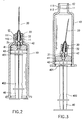
breaking the connecting tip 401 (see Figure 4). Then,
the plunger 40 is inserted into the front neck 12 of the
barrel 10 to deform the needle cannula 20. When the
needle cannula 20 is deformed, the locating groove 402
of the plunger 40 is engaged with the inside flange 11
of the front neck 12 of the barrel 10, and therefore the
plunger 40 is firmly retained to the front neck 12 of
the barrel 10.
It is to be understood that the drawings are
designed for purposes of illustration only, and are not
intended as a definition of the limits and scope of the
invention disclosed. For example, the retaining hole 31
can be made of conical shape, or in the form of a
triangular pyramid; the profile of the front end of the
retainer rod 42 fits the configuration of the retaining
hole 31 for positive engagement.
Claims (4)
- A safety hypodermic syringe comprising a barrel having a front neck and an inside flange inside said front neck, a needle holder inserted into said front neck of said barrel and retained in place by said inside flange of said front neck of said barrel, a needle cannula fastened to said needle holder, a plunger moved in said barrel, a rubber stopper connected to said plunger by a connecting member, wherein said inside flange of said front neck of said barrel has a front sloping wall of small slope and a rear sloping wall of different angles for permitting said needle holder to be pulled backwards to an inside of said barrel and for stopping said needle holder from being forced forwards out of said front neck of said barrel; said needle holder comprises a longitudinal center through hole, which imparts a passage between said needle cannula and said barrel, an inner thread around said longitudinal center through hole for mounting said needle cannula, and a rear retaining hole at one end of said longitudinal center through hole remote from said needle cannula; said connecting member has a connecting tip connected to said plunger that can be broken to let said plunger be disconnected from said connecting member; said rubber stopper has a retainer rod at a front end thereof fitting said retaining hole of said needle holder, said retaining rod being forced into engagement with said retaining hole of said needle holder when said rubber stopper is moved to said front neck of said barrel by said plunger, for permitting said needle holder with said needle cannula to be pulled backwards to said inside of said barrel by said plunger; said plunger can be inserted into said front neck of said barrel to deform said needle cannula when said needle holder and said needle cannula are moved to said inside of said barrel and said plunger is disconnected from the connecting tip of said connecting member; said plunger has a locating groove around a periphery of said plunger for engagement with said inside flange of said front neck of said barrel when it is inserted into front end of said barrel to deform said needle cannula.
- The safety hypodermic syringe of claim 1 wherein said retaining hole of said needle holder is made of arrowhead-like shape, and slopes from the longitudinal center axis of said needle holder in one direction.
- The safety hypodermic syringe of claim 1 wherein said retainer rod of said rubber stopper is shaped like an arrowhead fitting said retaining hole of said needle holder.
- The safety hypodermic syringe of claim 1 wherein said connecting member has at least one circular flange around said periphery fitting an inner diameter of said barrel.
Priority Applications (1)
| Application Number | Priority Date | Filing Date | Title |
|---|---|---|---|
| EP96306119A EP0824924A1 (en) | 1996-08-21 | 1996-08-21 | Safety hypodermic syringe |
Applications Claiming Priority (1)
| Application Number | Priority Date | Filing Date | Title |
|---|---|---|---|
| EP96306119A EP0824924A1 (en) | 1996-08-21 | 1996-08-21 | Safety hypodermic syringe |
Publications (1)
| Publication Number | Publication Date |
|---|---|
| EP0824924A1 true EP0824924A1 (en) | 1998-02-25 |
Family
ID=8225062
Family Applications (1)
| Application Number | Title | Priority Date | Filing Date |
|---|---|---|---|
| EP96306119A Withdrawn EP0824924A1 (en) | 1996-08-21 | 1996-08-21 | Safety hypodermic syringe |
Country Status (1)
| Country | Link |
|---|---|
| EP (1) | EP0824924A1 (en) |
Cited By (12)
| Publication number | Priority date | Publication date | Assignee | Title |
|---|---|---|---|---|
| WO2001007106A1 (en) * | 1999-07-27 | 2001-02-01 | Medi Plus Tec Medizinisch-Technische Handelsgesel Lschaft Mbh | Safety syringe |
| GB2360458A (en) * | 1999-07-19 | 2001-09-26 | Chang Lai Yu Hau | Safety syringe |
| WO2002013722A1 (en) * | 2000-08-11 | 2002-02-21 | Prima Technologies Limited | Needle nib insert |
| NL1020937C2 (en) * | 2002-06-25 | 2003-12-30 | Medical Patents Ltd | Injection syringe having retractable injection needle for medical applications, has liquid holder with outlet opening, plunger having plunger head, injection needle with needle amount mounted on outlet opening of holder |
| WO2004000398A1 (en) * | 2002-06-25 | 2003-12-31 | Medical Patents Limited | Injection syringe having a retractable injection needle |
| WO2004108196A1 (en) | 2003-06-04 | 2004-12-16 | Medsafe Asa | Disposable injection syringe |
| SG108303A1 (en) * | 2001-08-27 | 2005-01-28 | Lee Tun Chi | Safety device for a safety syringe |
| WO2010148614A1 (en) * | 2009-06-24 | 2010-12-29 | Chang Shu-Ming | Retractable structure of safety syringe |
| CN108904069A (en) * | 2018-05-29 | 2018-11-30 | 陈爱霞 | Removal-proof type safety shield for medical needles |
| WO2019179199A1 (en) * | 2018-02-12 | 2019-09-26 | 惠州海卓科赛医疗有限公司 | Elastic piston connecting structure, and high-pressure pumping system and method |
| WO2020034553A1 (en) * | 2018-08-15 | 2020-02-20 | 惠州海卓科赛医疗有限公司 | High pressure pump and high pressure pumping method |
| CN112827019A (en) * | 2021-01-06 | 2021-05-25 | 张峰 | Inward-rolling destroyer for medical syringe needle head of infectious disease department |
Citations (5)
| Publication number | Priority date | Publication date | Assignee | Title |
|---|---|---|---|---|
| US4710170A (en) * | 1987-02-12 | 1987-12-01 | Habley Medical Technology Corporation | Anti-needle strike and anti-drug abuse syringe |
| US5188597A (en) * | 1992-04-13 | 1993-02-23 | Becton, Dickinson And Company | Safety needle syringe |
| US5405327A (en) * | 1994-07-29 | 1995-04-11 | Chen; Long-Hsiung | Simplified safety syringe with retractable self-biased needle and minimized plunger |
| WO1995016478A1 (en) * | 1993-12-14 | 1995-06-22 | U.S. Medical Instruments, Inc. | Retractable syringe with a closed barrel |
| WO1996015820A1 (en) * | 1994-11-22 | 1996-05-30 | Tokita, Hiroshi | Injector |
-
1996
- 1996-08-21 EP EP96306119A patent/EP0824924A1/en not_active Withdrawn
Patent Citations (5)
| Publication number | Priority date | Publication date | Assignee | Title |
|---|---|---|---|---|
| US4710170A (en) * | 1987-02-12 | 1987-12-01 | Habley Medical Technology Corporation | Anti-needle strike and anti-drug abuse syringe |
| US5188597A (en) * | 1992-04-13 | 1993-02-23 | Becton, Dickinson And Company | Safety needle syringe |
| WO1995016478A1 (en) * | 1993-12-14 | 1995-06-22 | U.S. Medical Instruments, Inc. | Retractable syringe with a closed barrel |
| US5405327A (en) * | 1994-07-29 | 1995-04-11 | Chen; Long-Hsiung | Simplified safety syringe with retractable self-biased needle and minimized plunger |
| WO1996015820A1 (en) * | 1994-11-22 | 1996-05-30 | Tokita, Hiroshi | Injector |
Cited By (15)
| Publication number | Priority date | Publication date | Assignee | Title |
|---|---|---|---|---|
| GB2360458A (en) * | 1999-07-19 | 2001-09-26 | Chang Lai Yu Hau | Safety syringe |
| GB2360458B (en) * | 1999-07-19 | 2002-05-15 | Chang Lai Yu Hau | Safety syringe |
| WO2001007106A1 (en) * | 1999-07-27 | 2001-02-01 | Medi Plus Tec Medizinisch-Technische Handelsgesel Lschaft Mbh | Safety syringe |
| WO2002013722A1 (en) * | 2000-08-11 | 2002-02-21 | Prima Technologies Limited | Needle nib insert |
| SG108303A1 (en) * | 2001-08-27 | 2005-01-28 | Lee Tun Chi | Safety device for a safety syringe |
| NL1020937C2 (en) * | 2002-06-25 | 2003-12-30 | Medical Patents Ltd | Injection syringe having retractable injection needle for medical applications, has liquid holder with outlet opening, plunger having plunger head, injection needle with needle amount mounted on outlet opening of holder |
| WO2004000398A1 (en) * | 2002-06-25 | 2003-12-31 | Medical Patents Limited | Injection syringe having a retractable injection needle |
| WO2004108196A1 (en) | 2003-06-04 | 2004-12-16 | Medsafe Asa | Disposable injection syringe |
| JP2006526443A (en) * | 2003-06-04 | 2006-11-24 | メドセーフ アーエスアー | Disposable syringe |
| WO2010148614A1 (en) * | 2009-06-24 | 2010-12-29 | Chang Shu-Ming | Retractable structure of safety syringe |
| CN101927048B (en) * | 2009-06-24 | 2012-03-21 | 张淑茗 | Retraction structure of safety syringe |
| WO2019179199A1 (en) * | 2018-02-12 | 2019-09-26 | 惠州海卓科赛医疗有限公司 | Elastic piston connecting structure, and high-pressure pumping system and method |
| CN108904069A (en) * | 2018-05-29 | 2018-11-30 | 陈爱霞 | Removal-proof type safety shield for medical needles |
| WO2020034553A1 (en) * | 2018-08-15 | 2020-02-20 | 惠州海卓科赛医疗有限公司 | High pressure pump and high pressure pumping method |
| CN112827019A (en) * | 2021-01-06 | 2021-05-25 | 张峰 | Inward-rolling destroyer for medical syringe needle head of infectious disease department |
Similar Documents
| Publication | Publication Date | Title |
|---|---|---|
| US5575774A (en) | Structure of safety hypodermic syringe | |
| US5226882A (en) | Single-use syringe with non-retractable piston | |
| US5928202A (en) | Preloadable syringe for automated dispensing device | |
| US6189580B1 (en) | Vial transferset and method | |
| CA2321441C (en) | Retracting needle syringe | |
| CA2197573C (en) | Needle retraction mechanisms | |
| US4973309A (en) | Disposable syringe | |
| EP0824924A1 (en) | Safety hypodermic syringe | |
| EP0645154B1 (en) | Cartridge-needle unit having retractable needle | |
| US5591131A (en) | Safety minute dose hypodermic syringe | |
| US6554796B2 (en) | Safty hypodermic syringe and needle holder for same | |
| JP2003523266A (en) | Single use syringe | |
| HU182036B (en) | Injection syringe as well as needle holder and recipient belonging same | |
| HU221642B1 (en) | Safety syringe can be attached from the outside with retractable, pre-tensioned needle | |
| US5582594A (en) | Hypodermic syringe with a safe needle cap | |
| US5380297A (en) | Syringe | |
| US6613016B1 (en) | Safety hypodermic syringe | |
| US6423033B1 (en) | Safety hypodermic syringe | |
| WO2005004958A1 (en) | Hypodermic syringes | |
| US7371226B2 (en) | Plunger of a syringe | |
| CA2183823A1 (en) | Structure of safety hypodermic syringe | |
| US5562627A (en) | Safety syringe with retractable self-biased needle for intravenous injection without packing ring | |
| MXPA96003933A (en) | Structure of seguri hypodermic syringe | |
| WO2004105842A1 (en) | Syringes with restrictor | |
| JPH1057482A (en) | Microsyringe |
Legal Events
| Date | Code | Title | Description |
|---|---|---|---|
| PUAI | Public reference made under article 153(3) epc to a published international application that has entered the european phase |
Free format text: ORIGINAL CODE: 0009012 |
|
| AK | Designated contracting states |
Kind code of ref document: A1 Designated state(s): BE CH DE DK ES FR GB GR IT LI NL PT SE |
|
| 17P | Request for examination filed |
Effective date: 19980821 |
|
| AKX | Designation fees paid |
Free format text: BE CH DE DK ES FR GB GR IT LI NL PT SE |
|
| RBV | Designated contracting states (corrected) |
Designated state(s): BE CH DE DK ES FR GB GR IT LI NL PT SE |
|
| STAA | Information on the status of an ep patent application or granted ep patent |
Free format text: STATUS: THE APPLICATION IS DEEMED TO BE WITHDRAWN |
|
| 18D | Application deemed to be withdrawn |
Effective date: 20000301 |