EP0824241B1 - Barcode printing system and its control method - Google Patents
Barcode printing system and its control method Download PDFInfo
- Publication number
- EP0824241B1 EP0824241B1 EP97305890A EP97305890A EP0824241B1 EP 0824241 B1 EP0824241 B1 EP 0824241B1 EP 97305890 A EP97305890 A EP 97305890A EP 97305890 A EP97305890 A EP 97305890A EP 0824241 B1 EP0824241 B1 EP 0824241B1
- Authority
- EP
- European Patent Office
- Prior art keywords
- barcode
- checking
- unit
- printing
- reading
- Prior art date
- Legal status (The legal status is an assumption and is not a legal conclusion. Google has not performed a legal analysis and makes no representation as to the accuracy of the status listed.)
- Expired - Lifetime
Links
Images


Classifications
-
- G—PHYSICS
- G06—COMPUTING; CALCULATING OR COUNTING
- G06K—GRAPHICAL DATA READING; PRESENTATION OF DATA; RECORD CARRIERS; HANDLING RECORD CARRIERS
- G06K1/00—Methods or arrangements for marking the record carrier in digital fashion
- G06K1/12—Methods or arrangements for marking the record carrier in digital fashion otherwise than by punching
- G06K1/121—Methods or arrangements for marking the record carrier in digital fashion otherwise than by punching by printing code marks
Definitions
- the present invention relates to a barcode printing system and its control method and, more particularly, to a barcode printing system for printing and checking barcodes, and a control method of the system.
- Ink-jet printers form ejected inks by various schemes and attach them onto printing media such as recording paper sheets.
- ink-jet printers that use heat as energy for forming ejected inks have excellent features. That is, a plurality of ejection orifices can be arranged at high density, and such high-density arrangement allows to obtain a high-resolution, high-quality image at high speed and also to easily form a color image.
- the printers described in Japanese Patent Application Nos. 05-196196 and 06-110097 have a plurality of full-line type ink-jet print heads each having a width equal to that of the printing medium, and are applied to label printers and barcode printers that can obtain high-quality color images at high speed.
- print deterioration that does not pose any problem in a normal image may disturb reading of the image using a user's barcode reader.
- the barcode reader is directly set at the downstream side of the printer convey path to read the printed bar code, after the printed barcode is read, the read barcode data is compared with printed barcode data to check if the barcode is OK/NG, and error processing is done if necessary.
- EP-A-0472255 discloses a barcode testing apparatus in which the determination of whether the barcode is correct or not is based on the reading of one barcode at a time.
- an object of the present invention to provide a barcode printing system and its control method, which not only separate printing and barcode checking as independent processes but also simplify printer processing to allow to print a large number of barcodes at high speed and to satisfactorily check barcodes.
- a barcode printing system comprising: a printing unit for printing a barcode; and a checking unit which operates independently of said printing unit and checks the printed barcode, said printing unit comprising: setting means for setting a condition of a barcode to be printed in said checking unit prior to barcode printing; and control means for performing error processing when a barcode reading error message is received from said checking unit, the system being characterised in that said checking unit comprises: checking means for reading the printed barcode a plurality of times at different positions in accordance with information set by said setting means and checking the barcode; and informing means for informing said printing unit of an error when said checking means determines that the barcode is defective.
- a method of controlling a barcode printing system comprising a printing unit for printing a barcode, and a checking unit which operates independently of said printing unit and checks the printed barcode, said printing unit performing the steps of: a setting step of setting a condition of a barcode to be printed in said checking unit prior to barcode printing; and a control step of performing error processing when a barcode reading error message is received from said checking unit, characterised by said checking unit performing the steps of: a checking step of reading the printed barcode a plurality of times at different positions in accordance with information set in the setting step and checking the barcode; and an informing step of informing said printing unit of an error when it is determined in the checking step that the barcode is defective.
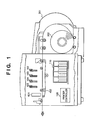
- Fig. 1 is a sectional view showing the structure of an ink-jet printer of this embodiment
- Fig. 2 is a schematic perspective view of the printer.
- reference numerals 102, 103, 104, and 105 denote full-line type ink-jet print heads each having a length corresponding to the maximum width of the printing medium used. These print heads 102, 103, 104, and 105 respectively eject black, cyan, magenta, and yellow inks from their ejection orifices toward a printing medium 302 at predetermined timings. Upon movement of the printing medium in correspondence with the above-mentioned timings, a color image is printed on the printing medium 302.
- Reference numeral 120 denotes a printer controller for controlling the overall printer; and 110, an ink tank.
- this embodiment exemplifies a roll of continuous label paper as the printing medium 302, and label paper supplied from a roll supply unit 301 is conveyed at a prescribed speed by a convey unit 402 arranged below the print heads.
- a reading unit 601 (to be referred to as a barcode checker unit hereinafter) for reading the printed barcode information and checking if the printed barcode is normal is arranged between the print head 105 and the discharge port of the printing medium.
- the barcode checker unit 601 operates independently, and its operation will be described in detail later. Of images to be printed, a barcode is recorded using the black print head 102. In addition, the remaining print heads 103 to 105 and the black print head 102 print a color image on a label sheet adhered on the surface of the printing medium 302.
- Fig. 3 is a block diagram of a control system of this embodiment.
- a print control circuit unit 501 controls an I/F unit 503 for interfacing with an external device, an operation unit control circuit 504, and a roll supply control circuit 505, and also controls overall printing such as processing of a print image, and the like.
- a head convey control circuit 502 performs ejection control of the plurality of print heads, control of the convey unit, control of a recovery system unit (not shown), and the like.
- the barcode checker unit 601 comprises a barcode OK/NG checking circuit 602 and a reader 603, which operate independently, and is connected to the print control circuit unit 501 via lines for a DATA signal for performing serial communications, an RD_TRG signal for instructing the barcode read timing, and an ERROR signal output when the barcode checking result is NG.
- the reader 603 is a line type reading device constituted by an infrared LED, CCD element, and optical system.
- the barcode OK/NG checking circuit 602 comprises a CPU which includes a ROM that stores a program and a RAM used as a work area.
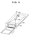
- Fig. 9 is a perspective view of the reader 603 in the barcode checker unit 601 in this embodiment.
- reference numeral 603a denotes an infrared LED, which has a width equal to that of the label paper to be conveyed.
- Reference numeral 603b denotes a reflection mirror for reflecting light reflected by the label paper (conveyed in the direction of an arrow in Fig. 9) toward a lens 603c.
- Reference numeral 603d denotes a line sensor for reading an image for one line formed by the lens 603c.
- print data including a barcode print command and barcode information
- a host computer not shown
- the printer prints in accordance with the print data to form copies in number designated by a control command in the print data.
- bitmap data, character data, and the like are printed in accordance with a known procedure, and the barcode print command and the barcode information will be described below.
- the barcode print command includes some parameters for defining the type, size, position, and the like of the barcode, and bitmap images of corresponding bars are created and printed in accordance with the barcode information that follows the command.
- the barcode OK/NG checking circuit 602 in the barcode checker unit 601 comprises a controller (microprocessor and the like), a ROM that stores the operation procedure of the controller, and a RAM for storing an OK counter to be described below.
- controller microprocessor and the like
- ROM read-only memory
- RAM random access memory
- the initial data include the type of barcode to be printed, the number of barcodes printed on a single line, the number of times of reading a single barcode and a reading OK ratio, and a value used when the barcode is read and is normally decoded.
- step S1 the OK counter is reset.
- step S2 it is checked if an RD_TRG signal as a barcode reading start signal is received from the print control circuit unit 501.
- step S3 If it is detected that this signal is received, the flow advances to step S3, and the reader 603 reads a barcode. It is checked in step S4 if the barcode is normally read and decoded and if the decoded value is equal to the value supplied from the print control circuit unit 501. If YES in step S4, the flow advances to step S5 to increment the contents of the OK counter by "1". Thereafter, the flow advances to step S6.
- step S6 it is checked if the barcode has been read a predetermined number m of times. If NO in step S6, the flow returns to step S3 and the operations for reading a barcode and checking if the barcode is normally read and decoded are repeated.
- the reader consequently reads a single barcode while crossing it at different positions, as shown in Fig. 8. That is, the barcode reader can be fixed in position.
- the number m of times of reading of a single barcode becomes a maximum of 16 when, for example, the print speed is 150 mm/s, the height of the barcode to be printed is 5 mm, and the reading speed of the reader 603 is 500 scans/s.
- the number m of times of reading of the barcode can be arbitrarily set within the range defined by the print speed, the height of the barcode to be printed, and the reading speed.
- the number m of times of reading of the barcode can be changed in correspondence with the height of the bar code.
- the operation processing procedure of the print control circuit unit 501 will be explained below.
- the print control circuit unit 501 has a microprocessor (CPU), a ROM that stores the operation processing procedure of the CPU, a RAM used as a work area, and N timers for counting clocks (not shown), as shown in Fig. 3, as in the barcode OK/NG checking circuit 602. Note that "N" represents the number of label sheets that can be present between the black print head 102 and the barcode checker unit 601.
- Fig. 5 shows the main routine of the print control circuit unit 501
- Fig. 6 shows the interrupt processing from the timer
- Fig. 7 shows the interrupt processing upon reception of the error signal.
- step S11 When a print instruction of a print image including a barcode is issued, developing processing of print data is started in the print control circuit unit 501 (step S11). During this processing, the print control circuit unit 501 transfers initial data for the barcode checker unit 601 including the type and value of the barcode to be printed, the number of barcodes to be printed on a single line, the number of times of reading of a single barcode and OK ratio, and the value to be obtained upon decoding, and the like, to the barcode checker unit 601 via the serial DATA signal line (step S12). Thereafter, a variable P is reset to "0" (step S13). After all the print pre-processing steps are completed, the label paper begins to be conveyed to start printing (step S14).
- the variable P herein has the following meaning. Assuming that a barcode is printed in black color alone using the print head 102, a certain time period is required until the barcode printed by an actual print head reaches the reading position of the barcode checker unit 601. In other words, during this time period, a plurality of printed barcodes are present, and the initially printed barcode reaches the reading position of the barcode checker unit 601 after a plurality of barcodes are printed on the printing medium. More simply, the RD_TRG signal must not be output to the barcode checker unit 601 until the initially printed barcode reaches the barcode checker unit 601. The variable P is used for the purpose of achieving this control.
- step S15 Upon completion of printing one barcode, the flow advances to step S15 to increment the variable P by "1". In addition, one of the timers is selected and started.
- step S14 the processing in step S14 and the subsequent steps is repeated until it is determined that printing of a pre-set number of copies is complete.
- step S17 If it is determined that printing has been completed, the control waits in step S17 until the variable P becomes "0". If the variable P becomes "0", driving of the convey system is stopped in step S18 to end a series of processing operations.
- the selected timer starts counting of clocks in step S15.
- the count of the timer has reached a pre-set value, it outputs an interrupt signal to the internal CPU of the print control circuit unit 501.
- This pre-set value corresponds to a time required until the printing medium printed with a barcode is conveyed to the reading position of the barcode checker unit 601 at the next timing.
- the CPU Upon reception of this interrupt signal, the CPU executes the timer interrupt processing corresponding to the flow chart in Fig. 6.
- step S20 it is checked in step S20 if printing has been completed. If NO in step S20, the flow advances to step S21 to check if the value of the variable P is larger than a predetermined value M.
- the predetermined value M indicates the number of printed label sheets that can be present between the print head and the barcode checker unit 601.
- step S21 If it is determined in step S21 that the variable P ⁇ M, the printed barcode is not conveyed yet to the position of the barcode checker unit 601, thus ending this processing.
- step S21 if it is determined in step S21 that the variable P > M, since this indicates that the reading timing of the printed barcode has been reached, an RD_TRG signal is output to the barcode checker unit 601 in step S22 to check the barcode by the above-mentioned method. Thereafter, the variable P is decremented by "1" to end this processing.
- step S20 is required since unchecked label sheets still remain before the position of the barcode checker unit at the timing of completion of printing. That is, barcode checking continues until the variable P becomes "0", and the processing ends upon completion of checking of all the barcodes.
- the barcode checker unit 601 when barcodes are not normally printed due to, e.g., non-ejection of the head, the barcode checker unit 601 outputs an error signal.
- the print control circuit unit 501 Upon reception of the error signal, the print control circuit unit 501 executes the error signal interrupt processing shown in Fig. 7.
- step S31 a warning indicating that errors have occurred is produced externally (e.g., by driving a buzzer or the like), and appropriate error processing such as stopping of printing (also stopping conveying of the printing medium), circulation of ink, wiping of the print head surface, and the like, is executed. If it is determined that a series of error recovery processing operations have been completed (step S32), this processing ends. Note that the error recovery processing can be mechanically automated to some extent, but often requires manual operations when, for example, the head must be exchanged. For this reason, the warning indicating errors is produced.
- This embodiment adopts the heads that eject inks by bubbles produced by heat energy. Since the print head of this type can easily realize a higher resolution and a high print speed, it is convenient for printing barcodes. However, as the number of times of driving per unit time increases, the temperature of nozzles in the print head is likely to increase as well as the number of ejected inks. Hence, barcode lines become thicker after printing for a long period of time, and the barcode checker unit consequently determines errors. In such situation, the number of times of driving per unit time can be decreased. That is, the control for decreasing the convey speed of the printing medium can be performed.
- a single barcode is printed on one printing medium for the sake of simplicity.
- a plurality of barcodes are normally printed on a single printing medium.
- the RD_TRG signal is kept output while one printed printing medium is passing the reader of the barcode checker unit, and OK/NG checking is performed after all the printed barcodes are read and checked. Alternatively, every time the printed barcode has reached the reading position, reading, checking, and OK/NG checking are done.
- the threshold value Th as the OK/NG checking criterion of barcode reading is set in accordance with an instruction from the print control circuit unit 501.
- this value may be fixed, or the print control circuit unit 501 may set this value in accordance with a predetermined command and its parameter in print data supplied from a print data generation source. Alternatively, this value may be set by an operation panel (not shown).
- the line sensor is used as the barcode reader.
- a laser scan type reader can be used, needless to say. Such reader will be described in the second embodiment.
- the processing in the print control circuit unit 501 is realized by interrupt processing.
- the processing of the unit 501 can also be realized by a series of processing operations.
- the processing of the unit 501 is not limited to specific processing, but may be modified within the scope of the above embodiment.
- a barcode is read by the line sensor in the reader 603.
- the second embodiment will exemplify a case wherein a barcode is read by scanning a laser beam onto a barcode portion by exposure and detecting light randomly reflected by the barcode portion.
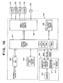
- Fig. 10 is a block diagram showing a control system in the second embodiment. The difference from Fig. 3 is the arrangement of a barcode checker unit.
- reference numeral 601 denotes a barcode checker unit in the second embodiment.
- the barcode checker unit 601 operates independently as in the first embodiment.
- Reference numeral 611 denotes a barcode OK/NG checking circuit; and 612, a reader.
- the basic functions of the barcode OK/NG checking circuit 611 and the reader 612 are the same as those in the first embodiment.
- Reference numeral 613 denotes a motor for adjusting the reading angle of the reader 612.
- Fig. 11 shows the arrangement of the reader 612 and that around the motor 613.
- Fig. 11 is a perspective view of the reader 11 which is stored in a single housing in practice.
- the reader 612 is constituted by a laser light-emitting element 612a, a polygonal mirror 612b, a motor 612c for rotating the polygonal mirror 612b at constant speed, a lens 612d for imaging light reflected by the reading surface (label), and a light-receiving element 612e.
- An arm 612e is fixed to the housing of the reader 612, as shown in Fig. 11, and is also fixed to the inner portion of the printer to be pivotal about a portion in the vicinity of the distal end of the arm 612e as a fulcrum.
- One end of a coil spring 612f is connected to the housing on the side opposite to the arm 612e, and the other end thereof is connected to a predetermined position inside the printer. With this arrangement, the reader 612 contacts the side surface of an eccentric cam 614 fixed to the rotation shaft of the motor 613 at a predetermined pressure.
- the number m of times of reading is calculated to be a maximum of "3" when, for example, the convey speed of a printing medium 302 is 150 mm/s, the minimum height of the barcode to be printed is 5 mm, and the laser scan speed of the reader 612 is 100 scans/s.
- the laser scan scanning of the laser beam spot from the left to the right in Fig. 11
- the laser scan requires a predetermined period of time, a barcode is obliquely read by the above-mentioned reading mechanism, and the reading range by the last scan falls outside the barcode. For this reason, the number of times of reading in practice becomes "2".
- the laser beam is scanned from the left to the right in Fig. 11.
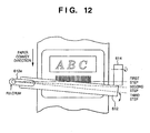
- the reader 612 in order to increase the number of times of reading, the reader 612 is pivoted about the fulcrum of the arm 612e, as shown in Fig. 12.
- reference numeral 614 denotes an eccentric cam (the cam which has a rotation central shaft at an eccentric position), which is rotated by the motor 613 via the rotation shaft of the motor 613 or some gears.
- the reader 612 is always biased by the spring 612f in a direction to contact the cam 614.
- the reading direction of the reader 612 can be changed like the first step, second step, third step,... in Fig. 12 depending on the pivot angle of the cam 614.
- This angle is set in accordance with the convey speed of the printing medium 302 and the angle determined in accordance with the convey speed and the scanning speed of the laser beam.
- the number of times of reading is determined based on the convey speed, the scanning speed of the laser beam (the number of scans per unit time), and the minimum height of a barcode.
- a print control circuit unit 501 in the second embodiment calculates the reading angle on the basis of the convey speed of label paper and the height of the barcode to be recorded, and transfers initial data including the calculated angle to the barcode checker unit 601 of the second embodiment, in the processing shown in Fig. 12.
- the barcode checker unit 601 drives the motor 613 in accordance with the reading angle in the initial data transferred from the print control circuit unit 501, and sets the scanning direction of the laser beam in a direction perpendicular to the convey direction of the label paper. Only this processing is added to that in the first embodiment.
- step S50 shown in Fig. 13 is added to the flow chart in Fig. 4.
- step S50 the motor 613 is driven in accordance with the convey speed of the label paper in setting information transferred from the print control circuit unit 501, and is stopped at the predetermined position.
- step S50 in Fig. 13 is the same as that in Fig. 4, and a detailed description thereof will be omitted.
- processing on the print control circuit unit 501 side is also the same as that in the first embodiment, and a detailed description thereof will be omitted.
- a single barcode is printed on one printing medium for the sake of simplicity.
- a plurality of barcodes are normally printed on a single printing medium.
- the RD_TRG signal is kept output while one printed printing medium is passing the reader of the barcode checker unit, and OK/NG checking is performed after all the printed barcodes are read and checked.
- OK/NG checking is performed after all the printed barcodes are read and checked.
- the threshold value Th as the OK/NG checking criterion of barcode reading is set in accordance with an instruction from the print control circuit unit 501.
- this value may be fixed, or the print control circuit unit 501 may set this value in accordance with a predetermined command and its parameter in print data supplied from a print data generation source. Alternatively, this value may be set by an operation panel (not shown).
- the barcode reader reads a barcode by scanning a laser beam.
- other schemes may be used.
- the reading angle of the reader 612 in the barcode checker unit is calculated by the print control circuit unit 501 (under the assumption that the reading speed of the reader 612 is known), and the calculated information is sent to the barcode checker unit.
- parameters required for calculating the angle may be input to the barcode checker unit, and the angle may be determined by the barcode checker unit to drive the motor.
- the number of times of reading can be calculated if the convey speed of the printing medium 302, the reading speed (the number of scans per unit time) of the reader 612, and the minimum height of the barcode are known, it can be calculated by the barcode checker side.
- the second embodiment uses the motor 613 as the means for changing the direction of the reader 612.
- a solenoid or any other means may be used.
- the barcode checker unit has the same structure as that of the first embodiment. Also, assume that the arrangements of the image print control circuit unit 501 and the barcode checker unit 601 are the same as those shown in Fig. 3. The operation processing contents of the image print control circuit unit 501 and the barcode OK/NG checking circuit 602 will be explained below with reference to Figs. 14 to 16.
- the operation processing of the image print control circuit unit 501 will be described below with reference to Fig. 14. Note that the image print control circuit unit 501 performs processing for storing data latched by the I/F unit 503 in a reception buffer area in its internal RAM in accordance with an interrupt signal from the I/F unit 503 when data is transferred from an external device to the I/F unit 503.
- step S101 data stored in the reception buffer is analyzed, and the analysis result is transferred to the barcode checker unit 601 as initial data.
- the initial data includes the convey speed of the printing medium, and the like.
- step S102 a variable P is initialized to "0".
- step S103 the data to be printed on the label is read out from the reception buffer. If the readout data includes a command associated with barcode printing, a value obtained by decoding that barcode, the print position of the barcode, and the height information of the barcode are transferred to the barcode checker unit 601 in step S104.
- step S105 a print image is developed on the RAM on the basis of the readout data. The image is printed in step S106.
- step S107 Upon completion of printing on a single label sheet, the flow advances to step S107 to increment the variable P by "1" and to start a timer. Note that a plurality of timers are used as in the first embodiment.
- step S108 it is checked if an end of printing is instructed. An end of printing is instructed when a command indicating this is received from the external device or when such command is input from an operation panel.
- step S108 the flow returns to step S103 to read out data to be printed on the next label.
- step S109 and the subsequent steps is the same as that in step S17 and the subsequent steps in Fig. 5, and a detailed description thereof will be omitted.
- Fig. 15 shows the interrupt processing executed when the barcode OK/NG checking circuit 602 in the barcode checker unit 601 receives barcode information from the image print control circuit unit 501.
- the barcode OK/NG checking circuit 602 Upon reception of barcode information (including a value obtained upon decoding the barcode, and information indicating the print position and height of the barcode) from the image print control circuit unit 501, the barcode OK/NG checking circuit 602 receives that information in step S201 in its interrupt processing. The flow advances to step S202, and the received barcode is stored in the RAM. Note that the RAM in the barcode OK/NG checking circuit 602 can store a plurality of pieces of barcode information. In practice, the RAM need only store barcode information corresponding in number to the label sheets present between the print head 102 that prints the barcodes and the barcode checker unit 601. However, if N barcodes are printed on a single label, the RAM must have an N-fold capacity.
- Fig. 16 shows the main routine of the barcode OK/NG checking circuit 602.
- step S211 the OK counter is reset.
- step S212 the control waits until a reading start signal RD_TRG signal is received from the image print control circuit unit 501. Upon reception of the reading start signal RD_TRG, the flow advances to step S213, and the oldest one of a plurality of pieces of unprocessed barcode information stored in the RAM is read out.
- step S214 and S219 are the same as steps S3 to S8 in Fig. 4.
- step S215 it is checked if the barcode is normally read (decoded) and if the value obtained by decoding the read barcode matches the barcode value read out from the RAM.
- an image including different barcodes can be printed on a label in addition to the effects of the first embodiment.
- the description of the third embodiment is given based on the first embodiment, but may be given based on the second embodiment. Hence, the third embodiment does not limit the present invention in any way.
- the barcode reading timing of the barcode checker unit is defined using the RD_TRG signal from the print control circuit unit 501.
- the fourth embodiment to be described below can obviate the need for this RD_TRG signal.
- Fig. 17 shows a printing medium 302 in the fourth embodiment.
- the printing medium 302 has label sheets 303, as in the first to third embodiments, and also has marks 304 used for determining the print position of each label sheet 303.
- the image print control circuit 501 and the barcode checker unit 601 respectively have means (e.g., light-receiving elements) for detecting these marks.
- the image print control circuit unit 501 calculates the print position of the barcode as coordinate data relative to the mark detection positions, and transfers it to the barcode checker unit 601 as a part of barcode information.
- the barcode checker unit 601 determines that a barcode is present at the coordinate position transferred from the image print control circuit unit 501, and can read the barcode at a predetermined timing. That is, in the previously described processing of the barcode checker unit 601, the processing for checking if an RD_TRG signal is received can be replaced by the processing for checking if marks are detected.
- a mark sensor 520 is connected to the print control circuit unit 501, and a mark sensor 620 is also connected to the barcode OK/NG checking circuit 602.
- the present invention may be applied to either a system constituted by a plurality of equipments (e.g., a host computer, an interface device, a reader, a printer, and the like), or an apparatus consisting of a single equipment (e.g., a copying machine, a facsimile apparatus, or the like).
- equipments e.g., a host computer, an interface device, a reader, a printer, and the like
- an apparatus consisting of a single equipment e.g., a copying machine, a facsimile apparatus, or the like.
- the objects of the present invention are also achieved by supplying a storage medium, which records a program code of a software program that can realize the functions of the above-mentioned embodiments to the system or apparatus, and reading out and executing the program code stored in the storage medium by a computer (or a CPU or MPU) of the system or apparatus.
- the program code itself read out from the storage medium realizes the functions of the above-mentioned embodiments, and the storage medium which stores the program code constitutes the present invention.
- the storage medium for supplying the program code for example, a floppy disk, hard disk, optical disk, magneto-optical disk, CD-ROM, CD-R, magnetic tape, nonvolatile memory card, ROM, and the like may be used.
- the functions of the above-mentioned embodiments may be realized not only by executing the readout program code by the computer but also by some or all of actual processing operations executed by an OS (operating system) running on the computer on the basis of an instruction of the program code.
- OS operating system
- the functions of the above-mentioned embodiments may be realized by some or all of actual processing operations executed by a CPU or the like arranged in a function extension board or a function extension unit, which is inserted in or connected to the computer, after the program code read out from the storage medium is written in a memory of the extension board or unit.
Description
- The present invention relates to a barcode printing system and its control method and, more particularly, to a barcode printing system for printing and checking barcodes, and a control method of the system.
- Ink-jet printers form ejected inks by various schemes and attach them onto printing media such as recording paper sheets. Among such printers, ink-jet printers that use heat as energy for forming ejected inks have excellent features. That is, a plurality of ejection orifices can be arranged at high density, and such high-density arrangement allows to obtain a high-resolution, high-quality image at high speed and also to easily form a color image.
- Of such ink-jet printers, the printers described in Japanese Patent Application Nos. 05-196196 and 06-110097 have a plurality of full-line type ink-jet print heads each having a width equal to that of the printing medium, and are applied to label printers and barcode printers that can obtain high-quality color images at high speed.
- Since such printer produces a bubble in ink by heat energy in each ejection orifice, and directly ejects the ink from the ejection orifice of a print head by the pressure of the bubble, it is required to always maintain a stable ejection state of the ink.
- However, ejection becomes unstable due to the influences of a bubble present in the ink, dried ink at the ejection orifice, attachment of paper dust onto the surface of the print head, and the like, resulting in non-ejection, mislanding of inks, and the like. In order to suppress non-ejection and mislanding of inks, such apparatus performs ink recovery at predetermined time intervals or exploits an improved recovery means, recovery sequence, and the like.
- However, it is impossible to completely prevent non-ejection and mislanding of inks, and the printed image may often deteriorate due to non-ejection or mislanding of inks that occur suddenly.
- In particular, when the printed image includes a barcode, print deterioration that does not pose any problem in a normal image may disturb reading of the image using a user's barcode reader.
- In order to prevent the above-mentioned problem that the printed barcode cannot be read by the barcode reader, for example, the barcode reader is directly set at the downstream side of the printer convey path to read the printed bar code, after the printed barcode is read, the read barcode data is compared with printed barcode data to check if the barcode is OK/NG, and error processing is done if necessary.
- However, in the method of comparing the printed barcode data and the read barcode data using the barcode reader, data transfer, data comparison, and the like between a control circuit of the printer and the barcode reader require much time. For this reason, during checking the barcode, printing must be interrupted or the print speed must be decreased, thus hampering high-speed printing. In order to realize high-speed data communications, a dedicated high-speed IF and the like must be inserted between the barcode reader and the control circuit, and the control circuit itself must use a high-speed CPU, resulting in high cost.
- EP-A-0472255 discloses a barcode testing apparatus in which the determination of whether the barcode is correct or not is based on the reading of one barcode at a time.
- It is, therefore, an object of the present invention to provide a barcode printing system and its control method, which not only separate printing and barcode checking as independent processes but also simplify printer processing to allow to print a large number of barcodes at high speed and to satisfactorily check barcodes.
- According to a first aspect of the present invention, there is provided a barcode printing system comprising: a printing unit for printing a barcode; and a checking unit which operates independently of said printing unit and checks the printed barcode, said printing unit comprising: setting means for setting a condition of a barcode to be printed in said checking unit prior to barcode printing; and control means for performing error processing when a barcode reading error message is received from said checking unit, the system being characterised in that said checking unit comprises: checking means for reading the printed barcode a plurality of times at different positions in accordance with information set by said setting means and checking the barcode; and informing means for informing said printing unit of an error when said checking means determines that the barcode is defective.
- According to a second aspect of the present invention, there is provided a method of controlling a barcode printing system comprising a printing unit for printing a barcode, and a checking unit which operates independently of said printing unit and checks the printed barcode, said printing unit performing the steps of: a setting step of setting a condition of a barcode to be printed in said checking unit prior to barcode printing; and a control step of performing error processing when a barcode reading error message is received from said checking unit, characterised by said checking unit performing the steps of: a checking step of reading the printed barcode a plurality of times at different positions in accordance with information set in the setting step and checking the barcode; and an informing step of informing said printing unit of an error when it is determined in the checking step that the barcode is defective.
- Other features and advantages of the present invention will be apparent from the following description, which is given by way of example only, taken in conjunction with the accompanying drawings, in which like reference characters designate the same or similar parts throughout the figures thereof.
-
- Fig. 1 is a sectional view showing the structure of a barcode printer according to the first embodiment of the present invention;
- Fig. 2 is a schematic perspective view of the barcode printer in the first embodiment;
- Fig. 3 is a block diagram showing the arrangement of a control system of the barcode printer in the first embodiment;
- Fig. 4 is a flow chart showing the processing procedure of a barcode checker in the first embodiment;
- Fig. 5 is a flow chart showing the processing procedure of the main routine of a print control circuit unit in the first embodiment;
- Fig. 6 is a flow chart showing the timer interrupt processing procedure of the print control circuit unit in the first embodiment;
- Fig. 7 is a flow chart showing the error interrupt processing procedure of the print control circuit unit in the first embodiment;
- Fig. 8 shows the relationship between the number of times of reading and the reading position of the barcode checker in the first embodiment;
- Fig. 9 is a perspective view showing the structure
of a
reader 603 in the first embodiment; - Fig. 10 is a block diagram showing a control system of a barcode printer according to the second embodiment of the present invention;
- Fig. 11 is a perspective view showing the structure
of a
reader 612 in the second embodiment; - Fig. 12 is a view for explaining the operation of
the
reader 612 in the second embodiment; - Fig. 13 is a flow chart showing the processing contents of a barcode checker unit in the second embodiment;
- Fig. 14 is a flow chart showing the processing
contents of a
print control circuit 501 in the third embodiment of the present invention; - Fig. 15 is a flow chart showing the interrupt processing in a barcode checker unit in the third embodiment;
- Fig. 16 is a flow chart showing the main routine in the barcode checker unit in the third embodiment;
- Fig. 17 shows a printing medium in the fourth embodiment of the present invention; and
- Fig. 18 is a block diagram showing a control system of a barcode printer of the fourth embodiment.
-
- Fig. 1 is a sectional view showing the structure of an ink-jet printer of this embodiment, and Fig. 2 is a schematic perspective view of the printer.
- Referring to Figs. 1 and 2,
reference numerals print heads printing medium 302 at predetermined timings. Upon movement of the printing medium in correspondence with the above-mentioned timings, a color image is printed on theprinting medium 302.Reference numeral 120 denotes a printer controller for controlling the overall printer; and 110, an ink tank. - Note that this embodiment exemplifies a roll of continuous label paper as the
printing medium 302, and label paper supplied from aroll supply unit 301 is conveyed at a prescribed speed by aconvey unit 402 arranged below the print heads. When the image to be printed includes barcode information, a reading unit 601 (to be referred to as a barcode checker unit hereinafter) for reading the printed barcode information and checking if the printed barcode is normal is arranged between theprint head 105 and the discharge port of the printing medium. - The
barcode checker unit 601 operates independently, and its operation will be described in detail later. Of images to be printed, a barcode is recorded using theblack print head 102. In addition, theremaining print heads 103 to 105 and theblack print head 102 print a color image on a label sheet adhered on the surface of theprinting medium 302. - Fig. 3 is a block diagram of a control system of this embodiment. A print
control circuit unit 501 controls an I/F unit 503 for interfacing with an external device, an operationunit control circuit 504, and a rollsupply control circuit 505, and also controls overall printing such as processing of a print image, and the like. A head conveycontrol circuit 502 performs ejection control of the plurality of print heads, control of the convey unit, control of a recovery system unit (not shown), and the like. - The
barcode checker unit 601 comprises a barcode OK/NG checking circuit 602 and areader 603, which operate independently, and is connected to the printcontrol circuit unit 501 via lines for a DATA signal for performing serial communications, an RD_TRG signal for instructing the barcode read timing, and an ERROR signal output when the barcode checking result is NG. Thereader 603 is a line type reading device constituted by an infrared LED, CCD element, and optical system. - The barcode OK/
NG checking circuit 602 comprises a CPU which includes a ROM that stores a program and a RAM used as a work area. - Fig. 9 is a perspective view of the
reader 603 in thebarcode checker unit 601 in this embodiment. - Referring to Fig. 9,
reference numeral 603a denotes an infrared LED, which has a width equal to that of the label paper to be conveyed.Reference numeral 603b denotes a reflection mirror for reflecting light reflected by the label paper (conveyed in the direction of an arrow in Fig. 9) toward alens 603c.Reference numeral 603d denotes a line sensor for reading an image for one line formed by thelens 603c. - With the above arrangement, for example, when print data (including a barcode print command and barcode information) is received from a host computer (not shown) connected to the I/
F unit 503, the printer prints in accordance with the print data to form copies in number designated by a control command in the print data. At this time, bitmap data, character data, and the like are printed in accordance with a known procedure, and the barcode print command and the barcode information will be described below. - The barcode print command includes some parameters for defining the type, size, position, and the like of the barcode, and bitmap images of corresponding bars are created and printed in accordance with the barcode information that follows the command.
- The processing contents of the
barcode checker unit 601 and the printcontrol circuit unit 501 in this embodiment will be described below with reference to the flow charts in Figs. 4 to 7. - The operation processing of the
barcode checker unit 601 will be described with reference to the flow chart in Fig. 4. Note that the barcode OK/NG checking circuit 602 in thebarcode checker unit 601 comprises a controller (microprocessor and the like), a ROM that stores the operation procedure of the controller, and a RAM for storing an OK counter to be described below. In the following description, assume that various initial data have been loaded and set from the printcontrol circuit unit 501. - The initial data include the type of barcode to be printed, the number of barcodes printed on a single line, the number of times of reading a single barcode and a reading OK ratio, and a value used when the barcode is read and is normally decoded.
- In step S1, the OK counter is reset. In step S2, it is checked if an RD_TRG signal as a barcode reading start signal is received from the print
control circuit unit 501. - If it is detected that this signal is received, the flow advances to step S3, and the
reader 603 reads a barcode. It is checked in step S4 if the barcode is normally read and decoded and if the decoded value is equal to the value supplied from the printcontrol circuit unit 501. If YES in step S4, the flow advances to step S5 to increment the contents of the OK counter by "1". Thereafter, the flow advances to step S6. - In step S6, it is checked if the barcode has been read a predetermined number m of times. If NO in step S6, the flow returns to step S3 and the operations for reading a barcode and checking if the barcode is normally read and decoded are repeated.
- During reading of a barcode, since the printing medium is conveyed at constant speed, the reader consequently reads a single barcode while crossing it at different positions, as shown in Fig. 8. That is, the barcode reader can be fixed in position.
- Upon completion of the m reading operations, the number of normally read barcodes is set in the OK counter. In step S7, it is checked if the OK ratio (= value of OK counter/m) is larger than a predetermined threshold value Th. If YES in step S7, the flow returns to step S1 to prepare for reading of the next barcode. On the other hand, if NO in step S7, this means that the print
control circuit unit 501 located at the upstream side is not normally printing, and an error signal is sent to the printcontrol circuit unit 501 via the ERROR signal line shown in Fig. 3. - Note that the number m of times of reading of a single barcode becomes a maximum of 16 when, for example, the print speed is 150 mm/s, the height of the barcode to be printed is 5 mm, and the reading speed of the
reader 603 is 500 scans/s. Of course, the number m of times of reading of the barcode can be arbitrarily set within the range defined by the print speed, the height of the barcode to be printed, and the reading speed. Also, the number m of times of reading of the barcode can be changed in correspondence with the height of the bar code. - The operation processing procedure of the print
control circuit unit 501 will be explained below. The printcontrol circuit unit 501 has a microprocessor (CPU), a ROM that stores the operation processing procedure of the CPU, a RAM used as a work area, and N timers for counting clocks (not shown), as shown in Fig. 3, as in the barcode OK/NG checking circuit 602. Note that "N" represents the number of label sheets that can be present between theblack print head 102 and thebarcode checker unit 601. - When the timer has counted a predetermined number of clocks and when an error signal is received from the
barcode checker unit 601 located at the downstream side, the corresponding interrupt processing operations are executed. - Fig. 5 shows the main routine of the print
control circuit unit 501, Fig. 6 shows the interrupt processing from the timer, and Fig. 7 shows the interrupt processing upon reception of the error signal. - The main routine shown in Fig. 5 will be explained below.
- When a print instruction of a print image including a barcode is issued, developing processing of print data is started in the print control circuit unit 501 (step S11). During this processing, the print
control circuit unit 501 transfers initial data for thebarcode checker unit 601 including the type and value of the barcode to be printed, the number of barcodes to be printed on a single line, the number of times of reading of a single barcode and OK ratio, and the value to be obtained upon decoding, and the like, to thebarcode checker unit 601 via the serial DATA signal line (step S12). Thereafter, a variable P is reset to "0" (step S13). After all the print pre-processing steps are completed, the label paper begins to be conveyed to start printing (step S14). - The variable P herein has the following meaning. Assuming that a barcode is printed in black color alone using the
print head 102, a certain time period is required until the barcode printed by an actual print head reaches the reading position of thebarcode checker unit 601. In other words, during this time period, a plurality of printed barcodes are present, and the initially printed barcode reaches the reading position of thebarcode checker unit 601 after a plurality of barcodes are printed on the printing medium. More simply, the RD_TRG signal must not be output to thebarcode checker unit 601 until the initially printed barcode reaches thebarcode checker unit 601. The variable P is used for the purpose of achieving this control. - Upon completion of printing one barcode, the flow advances to step S15 to increment the variable P by "1". In addition, one of the timers is selected and started.
- Thereafter, the processing in step S14 and the subsequent steps is repeated until it is determined that printing of a pre-set number of copies is complete.
- If it is determined that printing has been completed, the control waits in step S17 until the variable P becomes "0". If the variable P becomes "0", driving of the convey system is stopped in step S18 to end a series of processing operations.
- The selected timer starts counting of clocks in step S15. When the count of the timer has reached a pre-set value, it outputs an interrupt signal to the internal CPU of the print
control circuit unit 501. - This pre-set value corresponds to a time required until the printing medium printed with a barcode is conveyed to the reading position of the
barcode checker unit 601 at the next timing. - Upon reception of this interrupt signal, the CPU executes the timer interrupt processing corresponding to the flow chart in Fig. 6.
- More specifically, it is checked in step S20 if printing has been completed. If NO in step S20, the flow advances to step S21 to check if the value of the variable P is larger than a predetermined value M. The predetermined value M indicates the number of printed label sheets that can be present between the print head and the
barcode checker unit 601. - If it is determined in step S21 that the variable P ≤ M, the printed barcode is not conveyed yet to the position of the
barcode checker unit 601, thus ending this processing. - On the other hand, if it is determined in step S21 that the variable P > M, since this indicates that the reading timing of the printed barcode has been reached, an RD_TRG signal is output to the
barcode checker unit 601 in step S22 to check the barcode by the above-mentioned method. Thereafter, the variable P is decremented by "1" to end this processing. - Note that step S20 is required since unchecked label sheets still remain before the position of the barcode checker unit at the timing of completion of printing. That is, barcode checking continues until the variable P becomes "0", and the processing ends upon completion of checking of all the barcodes.
- As described above, printing and checking of barcodes are independently executed by separate devices, and the above-mentioned processing continues as long as barcodes are normally printed.
- However, as described above, when barcodes are not normally printed due to, e.g., non-ejection of the head, the
barcode checker unit 601 outputs an error signal. - Upon reception of the error signal, the print
control circuit unit 501 executes the error signal interrupt processing shown in Fig. 7. - In step S31, a warning indicating that errors have occurred is produced externally (e.g., by driving a buzzer or the like), and appropriate error processing such as stopping of printing (also stopping conveying of the printing medium), circulation of ink, wiping of the print head surface, and the like, is executed. If it is determined that a series of error recovery processing operations have been completed (step S32), this processing ends. Note that the error recovery processing can be mechanically automated to some extent, but often requires manual operations when, for example, the head must be exchanged. For this reason, the warning indicating errors is produced.
- This embodiment adopts the heads that eject inks by bubbles produced by heat energy. Since the print head of this type can easily realize a higher resolution and a high print speed, it is convenient for printing barcodes. However, as the number of times of driving per unit time increases, the temperature of nozzles in the print head is likely to increase as well as the number of ejected inks. Hence, barcode lines become thicker after printing for a long period of time, and the barcode checker unit consequently determines errors. In such situation, the number of times of driving per unit time can be decreased. That is, the control for decreasing the convey speed of the printing medium can be performed.
- In the above description, a single barcode is printed on one printing medium for the sake of simplicity. However, in practice, a plurality of barcodes are normally printed on a single printing medium.
- In this case, the RD_TRG signal is kept output while one printed printing medium is passing the reader of the barcode checker unit, and OK/NG checking is performed after all the printed barcodes are read and checked. Alternatively, every time the printed barcode has reached the reading position, reading, checking, and OK/NG checking are done.
- In the above description, the threshold value Th as the OK/NG checking criterion of barcode reading is set in accordance with an instruction from the print
control circuit unit 501. However, this value may be fixed, or the printcontrol circuit unit 501 may set this value in accordance with a predetermined command and its parameter in print data supplied from a print data generation source. Alternatively, this value may be set by an operation panel (not shown). - Furthermore, the line sensor is used as the barcode reader. Alternatively, a laser scan type reader can be used, needless to say. Such reader will be described in the second embodiment.
- In this embodiment, the processing in the print
control circuit unit 501 is realized by interrupt processing. However, the processing of theunit 501 can also be realized by a series of processing operations. Hence, the processing of theunit 501 is not limited to specific processing, but may be modified within the scope of the above embodiment. - As described above, according to this embodiment, since data communications required for barcode checking is ended before the beginning of printing, and an NG signal is output during printing only when it is determined that the printed barcode is NG, appropriate barcode checking can be attained without decreasing the print speed. Since the reading OK ratio can be arbitrarily set and barcode checking can be performed in correspondence with each customer's barcode reader, the barcode checking level required by the customer can be. set.
- Also, not only the unit for printing and the unit for checking barcodes are merely separated, but also the processing at the printing unit side is simplified to print a large number of barcodes at high speed and to attain satisfactory barcode checking.
- In the first embodiment, a barcode is read by the line sensor in the
reader 603. The second embodiment will exemplify a case wherein a barcode is read by scanning a laser beam onto a barcode portion by exposure and detecting light randomly reflected by the barcode portion. - Fig. 10 is a block diagram showing a control system in the second embodiment. The difference from Fig. 3 is the arrangement of a barcode checker unit. In Fig. 10,
reference numeral 601 denotes a barcode checker unit in the second embodiment. Thebarcode checker unit 601 operates independently as in the first embodiment.Reference numeral 611 denotes a barcode OK/NG checking circuit; and 612, a reader. The basic functions of the barcode OK/NG checking circuit 611 and thereader 612 are the same as those in the first embodiment.Reference numeral 613 denotes a motor for adjusting the reading angle of thereader 612. - Fig. 11 shows the arrangement of the
reader 612 and that around themotor 613. Fig. 11 is a perspective view of the reader 11 which is stored in a single housing in practice. - The
reader 612 is constituted by a laser light-emittingelement 612a, apolygonal mirror 612b, amotor 612c for rotating thepolygonal mirror 612b at constant speed, alens 612d for imaging light reflected by the reading surface (label), and a light-receivingelement 612e. Anarm 612e is fixed to the housing of thereader 612, as shown in Fig. 11, and is also fixed to the inner portion of the printer to be pivotal about a portion in the vicinity of the distal end of thearm 612e as a fulcrum. One end of acoil spring 612f is connected to the housing on the side opposite to thearm 612e, and the other end thereof is connected to a predetermined position inside the printer. With this arrangement, thereader 612 contacts the side surface of aneccentric cam 614 fixed to the rotation shaft of themotor 613 at a predetermined pressure. - When the
motor 613 is pivoted by an appropriate angle, theeccentric cam 614 pivots, and thereader 612 pivots along an arrow B to have the fulcrum as the center. As a result, the scanning direction of a laser spot that exposes a barcode can be changed. - The number m of times of reading of a single barcode described in the first embodiment will be examined below.
- Note that the number m of times of reading is calculated to be a maximum of "3" when, for example, the convey speed of a
printing medium 302 is 150 mm/s, the minimum height of the barcode to be printed is 5 mm, and the laser scan speed of thereader 612 is 100 scans/s. However, since the laser scan (scanning of the laser beam spot from the left to the right in Fig. 11) requires a predetermined period of time, a barcode is obliquely read by the above-mentioned reading mechanism, and the reading range by the last scan falls outside the barcode. For this reason, the number of times of reading in practice becomes "2". - Originally, since the reliability of the OK ratio as a criterion for checking if a barcode is normally recorded can become higher as the number of times of reading is larger, a larger number of times of reading is preferably set.
- In this situation, in the second embodiment, the laser beam is scanned from the left to the right in Fig. 11. In this case, in order to increase the number of times of reading, the
reader 612 is pivoted about the fulcrum of thearm 612e, as shown in Fig. 12. In Fig. 12,reference numeral 614 denotes an eccentric cam (the cam which has a rotation central shaft at an eccentric position), which is rotated by themotor 613 via the rotation shaft of themotor 613 or some gears. Thereader 612 is always biased by thespring 612f in a direction to contact thecam 614. - As a result, when the
cam 614 is pivoted, the reading direction of thereader 612 can be changed like the first step, second step, third step,... in Fig. 12 depending on the pivot angle of thecam 614. This angle is set in accordance with the convey speed of theprinting medium 302 and the angle determined in accordance with the convey speed and the scanning speed of the laser beam. The number of times of reading is determined based on the convey speed, the scanning speed of the laser beam (the number of scans per unit time), and the minimum height of a barcode. - With the above arrangement, even when a barcode reader which scans a laser beam by exposure at a relatively low speed is used, the number of times of reading can be maximized, and the reliability of the
barcode checker unit 601 can be improved. - Note that a print
control circuit unit 501 in the second embodiment calculates the reading angle on the basis of the convey speed of label paper and the height of the barcode to be recorded, and transfers initial data including the calculated angle to thebarcode checker unit 601 of the second embodiment, in the processing shown in Fig. 12. - The
barcode checker unit 601 drives themotor 613 in accordance with the reading angle in the initial data transferred from the printcontrol circuit unit 501, and sets the scanning direction of the laser beam in a direction perpendicular to the convey direction of the label paper. Only this processing is added to that in the first embodiment. For this purpose, step S50 shown in Fig. 13 is added to the flow chart in Fig. 4. In step S50, themotor 613 is driven in accordance with the convey speed of the label paper in setting information transferred from the printcontrol circuit unit 501, and is stopped at the predetermined position. - Note that the processing other than step S50 in Fig. 13 is the same as that in Fig. 4, and a detailed description thereof will be omitted. Also, the processing on the print
control circuit unit 501 side is also the same as that in the first embodiment, and a detailed description thereof will be omitted. - In the second embodiment as well, a single barcode is printed on one printing medium for the sake of simplicity. However, in practice, a plurality of barcodes are normally printed on a single printing medium.
- In this case, the RD_TRG signal is kept output while one printed printing medium is passing the reader of the barcode checker unit, and OK/NG checking is performed after all the printed barcodes are read and checked. Alternatively, every time a printed barcode has reached the reading position, reading, checking, and OK/NG checking are done.
- In the above description, the threshold value Th as the OK/NG checking criterion of barcode reading is set in accordance with an instruction from the print
control circuit unit 501. However, this value may be fixed, or the printcontrol circuit unit 501 may set this value in accordance with a predetermined command and its parameter in print data supplied from a print data generation source. Alternatively, this value may be set by an operation panel (not shown). - Furthermore, the barcode reader reads a barcode by scanning a laser beam. However, other schemes may be used.
- In the second embodiment, the reading angle of the
reader 612 in the barcode checker unit is calculated by the print control circuit unit 501 (under the assumption that the reading speed of thereader 612 is known), and the calculated information is sent to the barcode checker unit. Alternatively, parameters required for calculating the angle may be input to the barcode checker unit, and the angle may be determined by the barcode checker unit to drive the motor. - The same applies to the number of times of reading. Since the number of times of reading can be calculated if the convey speed of the
printing medium 302, the reading speed (the number of scans per unit time) of thereader 612, and the minimum height of the barcode are known, it can be calculated by the barcode checker side. - Furthermore, the second embodiment uses the
motor 613 as the means for changing the direction of thereader 612. For example, a solenoid or any other means may be used. - As described above, with the second embodiment as well, the same effect as in the first embodiment can be expected.
- That is, according to the second embodiment, since data communications required for barcode checking are ended before the beginning of printing, and an NG signal is output during printing only when it is determined that the printed barcode is NG, appropriate barcode checking can be attained without decreasing the print speed. Since the reading OK ratio can be arbitrarily set and barcode checking can be performed in correspondence with each customer's barcode reader, the barcode checking level required by the customer can be set.
- Also, not only the unit for printing and the unit for checking barcodes are merely separated, but also the processing at the printing unit side is simplified to print a large number of barcodes at high speed and to attain satisfactory barcode checking.
- In the first and second embodiments described above, a plurality of copies of an identical barcode are printed. In the third embodiment, different barcodes are printed, and their authenticities are checked.
- For the sake of simplicity, assume that the barcode checker unit has the same structure as that of the first embodiment. Also, assume that the arrangements of the image print
control circuit unit 501 and thebarcode checker unit 601 are the same as those shown in Fig. 3. The operation processing contents of the image printcontrol circuit unit 501 and the barcode OK/NG checking circuit 602 will be explained below with reference to Figs. 14 to 16. - The operation processing of the image print
control circuit unit 501 will be described below with reference to Fig. 14. Note that the image printcontrol circuit unit 501 performs processing for storing data latched by the I/F unit 503 in a reception buffer area in its internal RAM in accordance with an interrupt signal from the I/F unit 503 when data is transferred from an external device to the I/F unit 503. - In step S101, data stored in the reception buffer is analyzed, and the analysis result is transferred to the
barcode checker unit 601 as initial data. The initial data includes the convey speed of the printing medium, and the like. The flow advances to step S102, and a variable P is initialized to "0". In step S103, the data to be printed on the label is read out from the reception buffer. If the readout data includes a command associated with barcode printing, a value obtained by decoding that barcode, the print position of the barcode, and the height information of the barcode are transferred to thebarcode checker unit 601 in step S104. The flow then advances to step S105, and a print image is developed on the RAM on the basis of the readout data. The image is printed in step S106. - Upon completion of printing on a single label sheet, the flow advances to step S107 to increment the variable P by "1" and to start a timer. Note that a plurality of timers are used as in the first embodiment.
- When the flow reaches step S108, it is checked if an end of printing is instructed. An end of printing is instructed when a command indicating this is received from the external device or when such command is input from an operation panel.
- If NO in step S108, the flow returns to step S103 to read out data to be printed on the next label.
- The processing in step S109 and the subsequent steps is the same as that in step S17 and the subsequent steps in Fig. 5, and a detailed description thereof will be omitted.
- The processing executed upon reception of an interrupt signal from one of the timers and the processing upon reception of an error signal from the
barcode checker unit 601 are the same as those shown in Figs. 6 and 7 of the first embodiment, and a detailed description thereof will be omitted. - The operation processing of the
barcode checker unit 601 will be described below. Fig. 15 shows the interrupt processing executed when the barcode OK/NG checking circuit 602 in thebarcode checker unit 601 receives barcode information from the image printcontrol circuit unit 501. - Upon reception of barcode information (including a value obtained upon decoding the barcode, and information indicating the print position and height of the barcode) from the image print
control circuit unit 501, the barcode OK/NG checking circuit 602 receives that information in step S201 in its interrupt processing. The flow advances to step S202, and the received barcode is stored in the RAM. Note that the RAM in the barcode OK/NG checking circuit 602 can store a plurality of pieces of barcode information. In practice, the RAM need only store barcode information corresponding in number to the label sheets present between theprint head 102 that prints the barcodes and thebarcode checker unit 601. However, if N barcodes are printed on a single label, the RAM must have an N-fold capacity. - Fig. 16 shows the main routine of the barcode OK/
NG checking circuit 602. - In step S211, the OK counter is reset. In step S212, the control waits until a reading start signal RD_TRG signal is received from the image print
control circuit unit 501. Upon reception of the reading start signal RD_TRG, the flow advances to step S213, and the oldest one of a plurality of pieces of unprocessed barcode information stored in the RAM is read out. - The subsequent steps S214 and S219 are the same as steps S3 to S8 in Fig. 4. In step S215, however, it is checked if the barcode is normally read (decoded) and if the value obtained by decoding the read barcode matches the barcode value read out from the RAM.
- With the above-mentioned processing, according to the third embodiment, an image including different barcodes can be printed on a label in addition to the effects of the first embodiment.
- Note that the description of the third embodiment is given based on the first embodiment, but may be given based on the second embodiment. Hence, the third embodiment does not limit the present invention in any way.
- In the first to third embodiments described above, the barcode reading timing of the barcode checker unit is defined using the RD_TRG signal from the print
control circuit unit 501. The fourth embodiment to be described below can obviate the need for this RD_TRG signal. - Fig. 17 shows a
printing medium 302 in the fourth embodiment. As shown in Fig. 17, theprinting medium 302 haslabel sheets 303, as in the first to third embodiments, and also hasmarks 304 used for determining the print position of eachlabel sheet 303. - The image
print control circuit 501 and thebarcode checker unit 601 respectively have means (e.g., light-receiving elements) for detecting these marks. When a barcode is printed on thelabel sheet 303, the image printcontrol circuit unit 501 calculates the print position of the barcode as coordinate data relative to the mark detection positions, and transfers it to thebarcode checker unit 601 as a part of barcode information. - When the mark detection means detects marks, the
barcode checker unit 601 determines that a barcode is present at the coordinate position transferred from the image printcontrol circuit unit 501, and can read the barcode at a predetermined timing. That is, in the previously described processing of thebarcode checker unit 601, the processing for checking if an RD_TRG signal is received can be replaced by the processing for checking if marks are detected. - In this case, the block arrangement of the apparatus of this embodiment is as shown in Fig. 18. As shown in Fig. 18, a
mark sensor 520 is connected to the printcontrol circuit unit 501, and amark sensor 620 is also connected to the barcode OK/NG checking circuit 602. - Note that the present invention may be applied to either a system constituted by a plurality of equipments (e.g., a host computer, an interface device, a reader, a printer, and the like), or an apparatus consisting of a single equipment (e.g., a copying machine, a facsimile apparatus, or the like).
- The objects of the present invention are also achieved by supplying a storage medium, which records a program code of a software program that can realize the functions of the above-mentioned embodiments to the system or apparatus, and reading out and executing the program code stored in the storage medium by a computer (or a CPU or MPU) of the system or apparatus.
- In this case, the program code itself read out from the storage medium realizes the functions of the above-mentioned embodiments, and the storage medium which stores the program code constitutes the present invention.
- As the storage medium for supplying the program code, for example, a floppy disk, hard disk, optical disk, magneto-optical disk, CD-ROM, CD-R, magnetic tape, nonvolatile memory card, ROM, and the like may be used.
- The functions of the above-mentioned embodiments may be realized not only by executing the readout program code by the computer but also by some or all of actual processing operations executed by an OS (operating system) running on the computer on the basis of an instruction of the program code.
- Furthermore, the functions of the above-mentioned embodiments may be realized by some or all of actual processing operations executed by a CPU or the like arranged in a function extension board or a function extension unit, which is inserted in or connected to the computer, after the program code read out from the storage medium is written in a memory of the extension board or unit.
- As many apparently widely different embodiments of the present invention can be made without departing from the scope thereof, it is to be understood that the invention is not limited to the specific embodiments thereof except as defined in the appended claims.
Claims (20)
- A barcode printing system comprising:a printing unit (102-105, 110, 120) for printing a barcode; anda checking unit (601) which operates independently of said printing unit and checks the printed barcode,said printing unit comprising:the system being characterised in thatsetting means (501) for setting a condition of a barcode to be printed in said checking unit (601) prior to barcode printing; andcontrol means for performing error processing when a barcode reading error message is received from said checking unit,said checking unit (601) comprises:checking means (602, 603; 611, 612) for reading the printed barcode a plurality of times at different positions in accordance with information set by said setting means and checking the barcode; andinforming means (602, 611) for informing said printing unit (102-105, 110, 120) of an error when said checking means determines that the barcode is defective.
- The system according to claim 1 wherein said checking unit (601) checks the barcode by scanning a light beam on the printed barcode, the checking unit including adjustment means (613, 614) for adjusting a scanning angle of the light beam in accordance with information set by said setting means (501),
wherein said checking means (611, 612) reads the printed barcode a plurality of times at different positions by scanning the light beam at the angle adjusted by said adjustment means, and
checks the barcode. - The system according to claim 1 or 2, wherein a print head in said printing unit comprises a head for ejecting ink (102, 103, 104, 105).
- The system according to claim 3, wherein said print head comprises a head for ejecting ink (102, 103, 104, 105) by heat energy.
- The system according to claim 1 or 2, wherein said printing unit comprises a print head having a length corresponding to a width of a printing medium, and prints a barcode in a direction perpendicular to a convey direction of the printing medium; and
said checking unit (601) reads the barcode in the direction perpendicular to the convey direction of the printing medium. - The system according to claim 1 or 2, wherein the information set by said setting means includes the number of times of reading in said checking unit.
- The system according to claim 1 or 2, wherein said checking means in said checking unit (601) checks the barcode by checking if the barcode normal reading ratio with respect to the number of times of reading is not less than a predetermined value.
- The system according to claim 2, wherein said adjustment means ( 613, 614) adjusts the scanning angle on the basis of a convey speed of the printing medium on which the barcode is printed, and the scanning speed of the light beam.
- The system according to claim 2, wherein the information set by said setting means (501) includes the number of times of reading and the scanning angle in said checking unit.
- A method of controlling a barcode printing system comprising a printing unit (102-105, 110, 120) for printing a barcode, and a checking unit (601) which operates independently of said printing unit and checks the printed barcode,
said printing unit performing the steps of:characterised bya setting step (S12; S101, S104) of setting a condition of a barcode to be printed in said checking unit (601) prior to barcode printing; anda control step (S31) of performing error processingwhen a barcode reading error message is received from said checking unit (601),
said checking unit performing the steps of:a checking step (S3, S4, S5, S6; S214-S217) of reading the printed barcode a plurality of times at different positions in accordance with information set in the setting step and checking the barcode ; andan informing step (S8; S219) of informing said printing unit of an error when it is determined in the checking step that the barcode is defective . - The method according to claim 10 wherein the checking unit checks the barcode by scanning a light beam on the printed barcode, said checking unit performing the steps of:an adjustment step (S50) of adjusting a scanning angle of the light beam in accordance with information set in the setting step; anda checking step (S3,S4,S5,S6) of reading the printed barcode a plurality of times at different positions by scanning the light beam at the angle adjusted in the adjustment step, andchecking the barcode.
- The method according to claim 10 or 11, wherein a print head in said printing unit comprises a head for ejecting ink (102, 103, 104, 105).
- The method according to claim 12, wherein said print head comprises a head for ejecting ink by heat energy (102, 103, 104, 105).
- The method according to claim 10 or 11, wherein said printing unit comprises a print head having a length corresponding to a width of a printing medium, and prints a barcode in a direction perpendicular to a convey direction of the printing medium; and
said checking unit (601) reads the barcode in the direction perpendicular to the convey direction of the printing medium. - The method according to claim 10 or 11, wherein the information set in the setting step includes the number of times of reading in said checking unit.
- The method according to claim 10 or 11, wherein the checking step of said checking unit includes the step of checking (S7; S218) the barcode by checking if a barcode normal reading ratio with respect to the number of times of reading is not less than a predetermined value.
- The method according to claim 11, wherein the adjustment step (S50) includes the step of adjusting the scanning angle on the basis of a convey speed of the printing medium on which the barcode is printed, and a scanning speed of the light beam.
- The method according to claim 11, wherein the information set in the setting step includes the number of times of reading and the scanning angle in said checking unit.
- A computer program including processor implementable instructions for performing a method according to any one of claims 10 to 18.
- A computer software product storing a computer program according to claim 19.
Applications Claiming Priority (6)
| Application Number | Priority Date | Filing Date | Title |
|---|---|---|---|
| JP211202/96 | 1996-08-09 | ||
| JP8211202A JPH1055401A (en) | 1996-08-09 | 1996-08-09 | Barcode printing system and its control method |
| JP21120296 | 1996-08-09 | ||
| JP247986/96 | 1996-09-19 | ||
| JP24798696A JP3280239B2 (en) | 1996-09-19 | 1996-09-19 | Barcode printing system and control method thereof |
| JP24798696 | 1996-09-19 |
Publications (3)
| Publication Number | Publication Date |
|---|---|
| EP0824241A2 EP0824241A2 (en) | 1998-02-18 |
| EP0824241A3 EP0824241A3 (en) | 1999-02-24 |
| EP0824241B1 true EP0824241B1 (en) | 2003-10-22 |
Family
ID=26518497
Family Applications (1)
| Application Number | Title | Priority Date | Filing Date |
|---|---|---|---|
| EP97305890A Expired - Lifetime EP0824241B1 (en) | 1996-08-09 | 1997-08-04 | Barcode printing system and its control method |
Country Status (3)
| Country | Link |
|---|---|
| US (1) | US6002844A (en) |
| EP (1) | EP0824241B1 (en) |
| DE (1) | DE69725665T2 (en) |
Families Citing this family (24)
| Publication number | Priority date | Publication date | Assignee | Title |
|---|---|---|---|---|
| WO2000058903A1 (en) * | 1999-03-30 | 2000-10-05 | Intermec Ip Corp. | A method and system for automatic data collection ('adc') symbol preparation |
| US6484933B1 (en) * | 1999-06-18 | 2002-11-26 | L.C. Code Ltd. | Automatic barcode creation for data transfer and retrieval |
| US20010035964A1 (en) * | 2000-04-20 | 2001-11-01 | Hiroyasu Kurashina | Tape cartridge, tape printing method, tape printing apparatus, and label-producing method |
| EP1380982A1 (en) * | 2002-07-08 | 2004-01-14 | Sicpa Holding S.A. | Method and device for coding articles |
| US7617982B1 (en) * | 2003-09-10 | 2009-11-17 | Ncr Corporation | Computer peripheral with integrated printer and bar code reader |
| US7625059B2 (en) * | 2006-11-22 | 2009-12-01 | Plastipak Packaging, Inc. | Digital printing plastic containers |
| US9272815B2 (en) | 2006-05-09 | 2016-03-01 | Plastipak Packaging, Inc. | Digital printing plastic container |
| US8522989B2 (en) * | 2006-05-09 | 2013-09-03 | Plastipak Packaging, Inc. | Plastic containers with a base coat thereon |
| AU2012211478B2 (en) * | 2006-11-22 | 2014-08-07 | Plastipak Packaging, Inc | Digital printing plastic containers |
| US8167414B1 (en) | 2008-06-18 | 2012-05-01 | Plastipak Packaging, Inc. | Printing apparatus, system and method |
| JP2011525445A (en) | 2008-06-24 | 2011-09-22 | プラスチパック パッケージング,インコーポレイテッド | Apparatus and method for printing articles having non-planar surfaces |
| CN102186676B (en) * | 2008-10-20 | 2014-12-03 | 普拉斯蒂派克包装公司 | Digital printing plastic containers with improved adhesion and recyclability |
| US10400118B2 (en) | 2008-10-20 | 2019-09-03 | Plastipak Packaging, Inc. | Methods and compositions for direct print having improved recyclability |
| US8876979B2 (en) | 2008-10-20 | 2014-11-04 | Plastipak Packaging, Inc. | Recyclable printed plastic container and method |
| US8360566B2 (en) * | 2009-04-09 | 2013-01-29 | Plastipak Packaging, Inc. | Method for printing |
| US8231212B2 (en) * | 2009-04-09 | 2012-07-31 | Plastipak Packaging, Inc. | Ink delivery system |
| CN102034071B (en) * | 2009-09-25 | 2014-07-09 | 神基科技股份有限公司 | Automatic test system and automatic test method for testing bar code identification device |
| US8564799B2 (en) * | 2010-03-10 | 2013-10-22 | Xerox Corporation | Print quality validation of print jobs using bitmapped image |
| CN102463747A (en) * | 2010-10-29 | 2012-05-23 | 北大方正集团有限公司 | Variable-data bar code printing method and variable-data bar code printing system |
| US10467513B2 (en) | 2015-08-12 | 2019-11-05 | Datamax-O'neil Corporation | Verification of a printed image on media |
| GB2567709B (en) * | 2017-10-18 | 2020-01-29 | Tsc Auto Id Tech Co Ltd | Online data validator of the printing unit |
| US11367173B2 (en) | 2018-12-06 | 2022-06-21 | Hewlett-Packard Development Company, L.P. | Captured image based validation of printed tokens |
| US11373071B2 (en) * | 2020-06-19 | 2022-06-28 | Datamax-O'neil Corporation | Methods and systems for operating a printing apparatus |
| JP7436959B2 (en) | 2020-07-20 | 2024-02-22 | ブラザー工業株式会社 | Printing device, computer program, control method |
Family Cites Families (22)
| Publication number | Priority date | Publication date | Assignee | Title |
|---|---|---|---|---|
| US3906203A (en) * | 1973-09-20 | 1975-09-16 | Monarch Marking Systems Inc | Data retrieval and error detection circuitry for a width-modulated bar-code scanning apparatus |
| US3932840A (en) * | 1973-10-15 | 1976-01-13 | Taplin Business Machines Incorporated | Error detection and sequence maintaining system for bar-code readers |
| US4251798A (en) * | 1978-05-31 | 1981-02-17 | Symbol Technologies | Portable laser scanning arrangement for and method of evaluating and validating bar code symbols |
| US4224508A (en) * | 1978-11-13 | 1980-09-23 | Recognition Equipment Incorporated | Error correcting bar code reader |
| US4339208A (en) * | 1980-09-25 | 1982-07-13 | Ncr Corporation | Optical sensing of wire matrix printers |
| US4414468A (en) * | 1981-05-18 | 1983-11-08 | International Business Machines Corporation | Systematic error correction in bar code scanner |
| US4449052A (en) * | 1981-11-30 | 1984-05-15 | International Business Machines Corporation | Method of printing and detecting optimum bar code test patterns |
| US5548110A (en) * | 1986-04-18 | 1996-08-20 | Cias, Inc. | Optical error-detecting, error-correcting and other coding and processing, particularly for bar codes, and applications therefor such as counterfeit detection |
| US4860226A (en) * | 1986-09-09 | 1989-08-22 | Martin Edward L | Method and apparatus for bar code graphics quality control |
| US5272322A (en) * | 1990-08-21 | 1993-12-21 | Dai Nippon Insatsu Kabushiki Kaisha | Identification mark reading apparatus |
| US5336874A (en) * | 1991-02-22 | 1994-08-09 | Alps Electric Co., Ltd. | Bar code reader with error detection and decode control |
| JPH05229542A (en) * | 1991-07-09 | 1993-09-07 | Fuji Facom Corp | Label printer and label tape therefor |
| WO1993003454A1 (en) * | 1991-07-29 | 1993-02-18 | Gtech Corporation | Printer with read-after-write/print quality checking |
| JPH05124313A (en) * | 1991-11-06 | 1993-05-21 | Brother Ind Ltd | Printing device having printed information reading function |
| JP3233981B2 (en) * | 1992-05-26 | 2001-12-04 | オリンパス光学工業株式会社 | Symbol information reader |
| DE69331456T2 (en) * | 1992-10-09 | 2002-11-07 | Matsushita Electric Ind Co Ltd | Verifiable optical character recognition |
| JP2579725B2 (en) * | 1992-11-30 | 1997-02-12 | 東北リコー株式会社 | Printing device |
| JP2607028B2 (en) * | 1993-04-15 | 1997-05-07 | 東北リコー株式会社 | Recording device |
| JPH0747670A (en) * | 1993-08-06 | 1995-02-21 | Canon Aptecs Kk | Printer |
| US5521368A (en) * | 1993-09-22 | 1996-05-28 | Olympus Optical Co., Ltd. | Barcode symbol reading system having function for detecting and correcting inclination of barcode symbol |
| JP3442859B2 (en) * | 1994-05-24 | 2003-09-02 | キヤノンファインテック株式会社 | Printing apparatus and method |
| US5761219A (en) * | 1996-07-12 | 1998-06-02 | Intermec Technologies Corporation | Error correction for PDF417 and other machine-readable symbologies |
-
1997
- 1997-08-04 EP EP97305890A patent/EP0824241B1/en not_active Expired - Lifetime
- 1997-08-04 US US08/905,399 patent/US6002844A/en not_active Expired - Lifetime
- 1997-08-04 DE DE69725665T patent/DE69725665T2/en not_active Expired - Lifetime
Also Published As
| Publication number | Publication date |
|---|---|
| DE69725665T2 (en) | 2004-07-29 |
| EP0824241A3 (en) | 1999-02-24 |
| DE69725665D1 (en) | 2003-11-27 |
| EP0824241A2 (en) | 1998-02-18 |
| US6002844A (en) | 1999-12-14 |
Similar Documents
| Publication | Publication Date | Title |
|---|---|---|
| EP0824241B1 (en) | Barcode printing system and its control method | |
| US6960036B1 (en) | Adjustment method of printing positions, a printing apparatus and a printing system | |
| US5953035A (en) | Printing apparatus and printing method for use with rolled sheet and cut sheet feeding units | |
| JPH05238004A (en) | Method and apparatus for recording, and matter recorded thereby | |
| JPH0596796A (en) | Method and device for recording | |
| JPH0532026A (en) | Recording device | |
| US7407251B2 (en) | Printing method, computer-readable medium, printing apparatus, printing system, and pattern for correction | |
| EP0802059A2 (en) | History information providing method for printing apparatus | |
| JP2863267B2 (en) | Image forming device | |
| JP3397426B2 (en) | Ink jet recording device | |
| US5731882A (en) | Image communication apparatus | |
| US6246484B1 (en) | Image reading apparatus and information processing apparatus having image reading function | |
| JP2004009529A (en) | Apparatus for recording and method for recording | |
| JPH07179248A (en) | Recorder | |
| JP2007130934A (en) | Inkjet recording apparatus | |
| JP2007098713A (en) | Recording device | |
| KR20030082404A (en) | Printing apparatus, printer driver, and buffer management method | |
| JP2001080065A (en) | Ink-jet image-forming apparatus | |
| JP4144852B2 (en) | Inkjet recording apparatus and inkjet recording method | |
| JP4266590B2 (en) | Recording apparatus and recording method | |
| US5812154A (en) | Ink jet recording apparatus for determining a timing for a record scan in accordance with a time required to transfer one band of data, and recording the image data | |
| JP2002127392A (en) | Recording device and recording method | |
| JP4280453B2 (en) | Recording apparatus and recording head temperature management method | |
| US11345176B2 (en) | Recording apparatus, control method, and storage medium | |
| JPH1086492A (en) | Bar code printing system and control method therefor |
Legal Events
| Date | Code | Title | Description |
|---|---|---|---|
| PUAI | Public reference made under article 153(3) epc to a published international application that has entered the european phase |
Free format text: ORIGINAL CODE: 0009012 |
|
| AK | Designated contracting states |
Kind code of ref document: A2 Designated state(s): DE FR GB IT |
|
| AX | Request for extension of the european patent |
Free format text: AL;LT;LV;RO;SI |
|
| PUAL | Search report despatched |
Free format text: ORIGINAL CODE: 0009013 |
|
| AK | Designated contracting states |
Kind code of ref document: A3 Designated state(s): AT BE CH DE DK ES FI FR GB GR IE IT LI LU MC NL PT SE |
|
| AX | Request for extension of the european patent |
Free format text: AL;LT;LV;RO;SI |
|
| 17P | Request for examination filed |
Effective date: 19990707 |
|
| AKX | Designation fees paid |
Free format text: DE FR GB IT |
|
| 17Q | First examination report despatched |
Effective date: 20020514 |
|
| GRAH | Despatch of communication of intention to grant a patent |
Free format text: ORIGINAL CODE: EPIDOS IGRA |
|
| RAP1 | Party data changed (applicant data changed or rights of an application transferred) |
Owner name: CANON FINETECH INC. |
|
| RAP3 | Party data changed (applicant data changed or rights of an application transferred) |
Owner name: CANON FINETECH INC. |
|
| GRAS | Grant fee paid |
Free format text: ORIGINAL CODE: EPIDOSNIGR3 |
|
| GRAA | (expected) grant |
Free format text: ORIGINAL CODE: 0009210 |
|
| AK | Designated contracting states |
Kind code of ref document: B1 Designated state(s): DE FR GB IT |
|
| REG | Reference to a national code |
Ref country code: GB Ref legal event code: FG4D |
|
| REF | Corresponds to: |
Ref document number: 69725665 Country of ref document: DE Date of ref document: 20031127 Kind code of ref document: P |
|
| ET | Fr: translation filed | ||
| PLBE | No opposition filed within time limit |
Free format text: ORIGINAL CODE: 0009261 |
|
| STAA | Information on the status of an ep patent application or granted ep patent |
Free format text: STATUS: NO OPPOSITION FILED WITHIN TIME LIMIT |
|
| 26N | No opposition filed |
Effective date: 20040723 |
|
| REG | Reference to a national code |
Ref country code: FR Ref legal event code: PLFP Year of fee payment: 20 |
|
| PGFP | Annual fee paid to national office [announced via postgrant information from national office to epo] |
Ref country code: GB Payment date: 20160803 Year of fee payment: 20 Ref country code: DE Payment date: 20160726 Year of fee payment: 20 Ref country code: IT Payment date: 20160822 Year of fee payment: 20 |
|
| PGFP | Annual fee paid to national office [announced via postgrant information from national office to epo] |
Ref country code: FR Payment date: 20160712 Year of fee payment: 20 |
|
| REG | Reference to a national code |
Ref country code: DE Ref legal event code: R071 Ref document number: 69725665 Country of ref document: DE |
|
| REG | Reference to a national code |
Ref country code: GB Ref legal event code: PE20 Expiry date: 20170803 |
|
| PG25 | Lapsed in a contracting state [announced via postgrant information from national office to epo] |
Ref country code: GB Free format text: LAPSE BECAUSE OF EXPIRATION OF PROTECTION Effective date: 20170803 |