EP0823790A2 - Dual band mobile station employing cross-connected transmitter and receiver circuits - Google Patents
Dual band mobile station employing cross-connected transmitter and receiver circuits Download PDFInfo
- Publication number
- EP0823790A2 EP0823790A2 EP97305918A EP97305918A EP0823790A2 EP 0823790 A2 EP0823790 A2 EP 0823790A2 EP 97305918 A EP97305918 A EP 97305918A EP 97305918 A EP97305918 A EP 97305918A EP 0823790 A2 EP0823790 A2 EP 0823790A2
- Authority
- EP
- European Patent Office
- Prior art keywords
- transmitter
- signals
- receiver
- frequency
- antenna
- Prior art date
- Legal status (The legal status is an assumption and is not a legal conclusion. Google has not performed a legal analysis and makes no representation as to the accuracy of the status listed.)
- Withdrawn
Links
- 230000009977 dual effect Effects 0.000 title description 16
- 239000010409 thin film Substances 0.000 claims abstract description 4
- 102000006463 Talin Human genes 0.000 claims description 32
- 108010083809 Talin Proteins 0.000 claims description 32
- 230000008878 coupling Effects 0.000 claims description 6
- 238000010168 coupling process Methods 0.000 claims description 6
- 238000005859 coupling reaction Methods 0.000 claims description 6
- 239000010408 film Substances 0.000 claims description 3
- 238000006243 chemical reaction Methods 0.000 description 11
- 230000001413 cellular effect Effects 0.000 description 5
- 230000015654 memory Effects 0.000 description 5
- 230000011664 signaling Effects 0.000 description 4
- IRLPACMLTUPBCL-KQYNXXCUSA-N 5'-adenylyl sulfate Chemical compound C1=NC=2C(N)=NC=NC=2N1[C@@H]1O[C@H](COP(O)(=O)OS(O)(=O)=O)[C@@H](O)[C@H]1O IRLPACMLTUPBCL-KQYNXXCUSA-N 0.000 description 3
- 230000005540 biological transmission Effects 0.000 description 3
- 238000010586 diagram Methods 0.000 description 2
- 230000010267 cellular communication Effects 0.000 description 1
- 238000004891 communication Methods 0.000 description 1
- 230000006870 function Effects 0.000 description 1
- 238000002347 injection Methods 0.000 description 1
- 239000007924 injection Substances 0.000 description 1
- 238000009434 installation Methods 0.000 description 1
- 230000010354 integration Effects 0.000 description 1
- 238000000034 method Methods 0.000 description 1
- 238000012986 modification Methods 0.000 description 1
- 230000004048 modification Effects 0.000 description 1
- 238000004806 packaging method and process Methods 0.000 description 1
- 239000004065 semiconductor Substances 0.000 description 1
- 239000000758 substrate Substances 0.000 description 1
Images


Classifications
-
- H—ELECTRICITY
- H04—ELECTRIC COMMUNICATION TECHNIQUE
- H04B—TRANSMISSION
- H04B1/00—Details of transmission systems, not covered by a single one of groups H04B3/00 - H04B13/00; Details of transmission systems not characterised by the medium used for transmission
- H04B1/005—Details of transmission systems, not covered by a single one of groups H04B3/00 - H04B13/00; Details of transmission systems not characterised by the medium used for transmission adapting radio receivers, transmitters andtransceivers for operation on two or more bands, i.e. frequency ranges
- H04B1/0053—Details of transmission systems, not covered by a single one of groups H04B3/00 - H04B13/00; Details of transmission systems not characterised by the medium used for transmission adapting radio receivers, transmitters andtransceivers for operation on two or more bands, i.e. frequency ranges with common antenna for more than one band
- H04B1/0057—Details of transmission systems, not covered by a single one of groups H04B3/00 - H04B13/00; Details of transmission systems not characterised by the medium used for transmission adapting radio receivers, transmitters andtransceivers for operation on two or more bands, i.e. frequency ranges with common antenna for more than one band using diplexing or multiplexing filters for selecting the desired band
-
- H—ELECTRICITY
- H04—ELECTRIC COMMUNICATION TECHNIQUE
- H04B—TRANSMISSION
- H04B1/00—Details of transmission systems, not covered by a single one of groups H04B3/00 - H04B13/00; Details of transmission systems not characterised by the medium used for transmission
- H04B1/005—Details of transmission systems, not covered by a single one of groups H04B3/00 - H04B13/00; Details of transmission systems not characterised by the medium used for transmission adapting radio receivers, transmitters andtransceivers for operation on two or more bands, i.e. frequency ranges
- H04B1/0053—Details of transmission systems, not covered by a single one of groups H04B3/00 - H04B13/00; Details of transmission systems not characterised by the medium used for transmission adapting radio receivers, transmitters andtransceivers for operation on two or more bands, i.e. frequency ranges with common antenna for more than one band
- H04B1/006—Details of transmission systems, not covered by a single one of groups H04B3/00 - H04B13/00; Details of transmission systems not characterised by the medium used for transmission adapting radio receivers, transmitters andtransceivers for operation on two or more bands, i.e. frequency ranges with common antenna for more than one band using switches for selecting the desired band
-
- H—ELECTRICITY
- H04—ELECTRIC COMMUNICATION TECHNIQUE
- H04B—TRANSMISSION
- H04B1/00—Details of transmission systems, not covered by a single one of groups H04B3/00 - H04B13/00; Details of transmission systems not characterised by the medium used for transmission
- H04B1/38—Transceivers, i.e. devices in which transmitter and receiver form a structural unit and in which at least one part is used for functions of transmitting and receiving
- H04B1/40—Circuits
- H04B1/403—Circuits using the same oscillator for generating both the transmitter frequency and the receiver local oscillator frequency
- H04B1/406—Circuits using the same oscillator for generating both the transmitter frequency and the receiver local oscillator frequency with more than one transmission mode, e.g. analog and digital modes
Definitions
- This invention relates generally to radiotelephones and, in particular, to dual band radiotelephones or mobile stations such as those capable of operation with a cellular network.
- dual mode When discussing a dual mode telecommunications system there are several different ways to define what is meant by “dual mode".
- the modes between which switching is possible may be analog/digital, or low/high carrier bit rate, or frequency/time division duplex (FDD/TDD), or simply from one frequency band to another.
- FDD/TDD frequency/time division duplex
- Various combinations of these parameters can also be encompassed by a dual mode mobile station (e.g., analog/digital and frequency band 1/frequency band 2).
- a dual mode mobile station e.g., analog/digital and frequency band 1/frequency band 2
- the parameters of most interest are duplexing mode and/or frequency band changes.
- RF radio frequency
- the frequency bands of interest may be widely spaced apart (e.g., 800 MHz and 1900 MHz), or they may be quite close together and even overlapping. Furthermore, within a band of interest, and for a duplex mode such as is used in conventional AMPS, transmission and reception occurs simultaneously at two different frequencies. This is a most troublesome case, as cross-talk between the transmitter and receiver circuitry degrades the voice and signalling quality of the mobile station.
- a multi-mode radiotelephone includes at least one antenna for transmitting and receiving RF signals within at least two frequency bands.
- the radiotelephone also includes a first receiver having an input coupled to the antenna for amplifying and down-converting RF signals within a first frequency band and a second receiver having an input coupled to the antenna for amplifying and down-converting RF signals within a second frequency band.
- the radiotelephone further includes a first transmitter having an output coupled to the antenna for up-converting and amplifying RF signals within the first frequency band and a second transmitter having an output coupled to the antenna for up-converting and amplifying RF signals within the second frequency band.
- the first receiver and the second transmitter are disposed within a first circuit package (i.e., are cross-connected), and the second receiver and the first transmitter are disposed within a second circuit package and are likewise cross-connected.
- the first and second circuit packages may be integrated circuits or hybrid circuits.
- the radiotelephone also includes a first local oscillator for use with the first frequency band, a second local oscillator for use with the second frequency band, and a switch assembly for switchably coupling an output of either the first local oscillator or the second local oscillator to the first and second circuit packages.
- the radiotelephone also includes a first duplexer for coupling the first receiver and the first transmitter to the antenna and a second duplexer for coupling the second receiver and the second transmitter to the antenna.
- switches are provided for selectively applying operating power to only one of the first receiver and the second receiver while also applying operating power to only one of the first transmitter and the second transmitter.
- a multi-mode transceiver comprising at least one antenna for transmitting and receiving RF signals within at least two frequency bands; a first receiver having an input coupled to said at least one antenna for receiving RF signals within a first frequency band; a second receiver having an input coupled to said at least one antenna for receiving RF signals within a second frequency band; a first transmitter having an output coupled to said at least one antenna for transmitting RF signals within the first frequency band; and a second transmitter having an output coupled to said at least one antenna for transmitting RF signals within the second frequency band; wherein said first receiver and said second transmitter are disposed within a first circuit package, and said second receiver and said first transmitter are disposed within a second circuit package.
- a transceiver comprising at least one antenna for transmitting and receiving RF signals within at least two frequency bands; a first local oscillator (LO1) for use with a first frequency band (Band1); a second local oscillator (LO2) for use with a second frequency band (Band2); a first receiver having an input coupled to said at least one antenna for amplifying and down-converting RF signals, within Band1, to a Band1 first intermediate frequency (IF1), the first receiver being switchably coupled to an output of LO1 for outputting IF1 to be a difference frequency between the frequency of Band1 and the frequency of LO1; a second receiver having an input coupled to said at least one antenna for amplifying and down-converting RF signals, within Band2, to a Band2 first intermediate frequency (IF2), the second receiver being switchably coupled to an output of LO2 for outputting IF2 to be a difference frequency between the frequency of Band2 and the frequency of LO2; a first transmitter having
- a transceiver comprising at least one antenna for transmitting and receiving RF signals within at least two frequency bands; a first receiver having an input coupled to said at least one antenna for amplifying RF signals, within a first frequency band (Band1), and for outputting a Band1 first intermediate frequency (IF1); a second receiver having an input coupled to said at least one antenna or amplifying RF signals, within a second frequency band (Band2), and for outputting a Band2 first intermediate frequency (IF2); a first transmitter having an output coupled to said at least one antenna for amplifying RF signals and for outputting a Band1 transmitted frequency (f TX1 ); and a second transmitter having an output coupled to said at least one antenna for amplifying RF signals and for outputting a Band2 transmitted frequency (f TX2 ); wherein at least a portion of said first receiver and said second transmitter are disposed within a first integrated circuit, and at least a portion of said second receiver and said first transmitter are disposed
- a multi-mode transceiver comprising at least one antenna for transmitting and receiving RF signals within at least two frequency bands; a first receiver having an input coupled to said at least one antenna for receiving RF signals within a first frequency band; a second receiver having an input coupled to said at least one antenna for receiving RF signals within a second frequency band; a first transmitter having an output coupled to said at least one antenna for transmitting RF signals within the first frequency band; and a second transmitter having an output coupled to said at least one antenna for transmitting RF signals within the second frequency band; wherein said first receiver and said second transmitter are cross-connected, and said second receiver and said first transmitter are cross-connected.
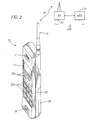
- FIG. 1 and 2 for illustrating a wireless user terminal or mobile station 10, such as but not limited to a dual mode cellular radiotelephone or a personal communicator, that is suitable for practicing this invention.
- the dual mode mobile station 10 includes an antenna 12 for transmitting signals to and for receiving signals from a base site or base station 30.
- the base station 30 is a part of a cellular network comprising the BMI 32 that includes a Mobile Switching Center (MSC) 34.
- the MSC 34 provides a connection to landline trunks when the mobile station 10 is registered with the network.
- MSC Mobile Switching Center
- the dual mode mobile station 10 is capable of establishing wireless communications using, by example, different modulation types (e.g., ⁇ /4-DQPSK and FM) and possibly also different frequency bands (e.g., 800 MHz AMPS or TDMA and 1900 PCS). Digital TDMA, digital CDMA, hybrid TDMA/CDMA, and duplex analog FM mobile stations are all within the scope of the teaching of this invention.
- modulation types e.g., ⁇ /4-DQPSK and FM
- FM possibly also different frequency bands
- FM e.g., 800 MHz AMPS or TDMA and 1900 PCS.
- Digital TDMA, digital CDMA, hybrid TDMA/CDMA, and duplex analog FM mobile stations are all within the scope of the teaching of this invention.
- the mobile station 10 may include a dual mode modulator (MOD) 14a, transmitter 14, receiver 16, demodulator (DEMOD) 16a.
- a controller 18 provides signals to and receives signals from the transmitter 14 and receiver 16, respectively. These signals include signalling information in accordance with the air interface standard of the applicable cellular system, and also user speach and/or user generated data.
- a user interface includes a conventional earphone or speaker 17, a conventional microphone 19, a display 20, and a user input device, typically a keypad 22, all of which are coupled to the controller 18.
- the keypad 22 includes the conventional numeric (0-9) and related keys (#,*) 22a, and other keys 22b used for operating the mobile station 10. These other keys 22b may include, by example, a SEND key, various menu scrolling and soft keys, and a PWR key.
- the mobile station 10 also includes various memories, shown collectively as the memory 24, wherein are stored a plurality of constants and variables that are used by the controller 18 during the operation of the mobile station.
- the memory 24 stores the values of various cellular system parameters and the number assignment module (NAM).
- NAM number assignment module
- An operating program for controlling the operation of controller 18 is also stored in the memory 24 (typically in a ROM device).
- the memory 24 may also store data, including user messages, that is received from the BMI 32 prior to the display of the messages to the user.
- the mobile station 10 also includes a battery 26 for powering the various circuits that are required to operate the station.
- the mobile station 10 can be a vehicle mounted or a handheld device. It should further be appreciated that the mobile station 10 can be capable of operating with one or more air interface standards, modulation types, and access types. By example, the mobile station may be capable of operating with any of a number of standards including IS-91, IS-136, GSM, DECT, PCS, UMTS, FPLMTS and IS-95. Narrow-band AMPS (NAMPS), as well as TACS, mobile stations may also benefit from the teaching of this invention. It should thus be clear that the teaching of this invention is not to be construed to be limited to any one particular type of mobile station or air interface standard.
- FIG. 3 illustrates a dual band transmitter/receiver (transceiver) portion of the mobile phone 10.
- the signal for Band1 is received by the antenna 12.
- the antenna 12 is shown as two antennas 12a and 12b which can be switched by switch 13 when the transceiver band is changed. A single wideband antenna can also be used, thereby eliminating switch 13.
- the received Band1 signal is passed through a Band1 duplexer 15a to a Band1 low noise amplifier (LNA) 30.
- the output of the LNA 30 is applied to a bandpass filter 32 and then to an RF down-conversion mixer 34.
- the mixer 34 is fed a first local oscillator (LO1) signal through a buffer 36.
- LO1 local oscillator
- the input of buffer 36 is derived from a LO switching arrangement 38.
- the output of mixer 34 is a first intermediate frequency (IF) signal that is applied to an IF buffer 40 which provides an output to an IF bandpass filter 42.
- the mixer 34 operates to down-convert the received Band1 signal to the first IF, which is equal to a difference frequency between Band1 and LO1.
- the Band2 receive circuitry 30a, 32a, 34a, 36a and 40a operates identically, except for using a second local oscillator (LO2) frequency.
- LO2 local oscillator
- Band1 and Band2 receive circuitry is disposed in separate integrated circuit packages 29a and 29b.
- the Band1 transmitter up-conversion mixer 44 is located in the integrated circuit package 29b that contains the Band2 receive circuitry.
- the Band2 transmitter up-conversion mixer 44a is located in the integrated circuit package 29a that contains the Band1 receive circuitry.
- the Band1 and Band2 circuits are considered to be "cross-connected", thereby eliminating signal cross-talk between the transmit and receive circuitry during duplex operation. That is, if the Band1 down-conversion mixer 34 and the Band1 up-conversion mixer 44, along with their associated amplifiers, were located in the same integrated circuit package, undesirable signal cross-talk could exist between these circuits during duplex operation (i.e., during the simultaneous use of the receiver and transmitter circuitry). The same applies to the Band2 circuitry.
- the teaching of this invention overcomes these problems by cross-connecting the circuitry as is shown in Figure 3.
- the transmit path for Band1 includes a LO1 buffer 46 which feeds the buffered LO1 injection signal to the up-conversion mixer 44.
- a modulating input signal (MOD) obtained from block 14a in Figure 1, representing speech, data, and/or signalling information, is applied to a second input of the up-conversion mixer 44.
- An output of mixer 44 is applied to a buffer amplifier 48 which has an output connected to an output terminal of the integrated circuit 29b.
- the buffered Band1 signal is next applied to a Band1 power amplifier section that includes a bandpass filter 50, a buffer amplifier 52, a variable gain amplifier (VGA) 54, and power amplifiers 56 and 58.
- VGA variable gain amplifier
- the output of the power amplifiers is a Band1 transmitted frequency f TX1 that is applied to the Band1 duplexer 15a and thence to the appropriate antenna 12a or 12b.
- the Band2 transmit circuitry is constructed identically, except for the use of LO2 for the up conversion mixer 44a and the use of the Band2 duplexer 15b.
- power switching circuits 60a and 60b for selectively supplying operating power to the Band1 and Band2 circuits located in the integrated circuits 29a and 29b, it being assumed for this embodiment that separate power terminals are provided for the receive and transmit sections. In this manner the mobile station 10 powers down or powers off the transmitter and receiver circuitry of the frequency band that is not currently being used.
- the teaching of this invention applies to multi-mode devices capable of operation in two or more frequency bands.
- the teaching of this invention is not restricted for use with transceiver integrated circuits, but can be applied as well to hybrid circuit packages, such as those wherein discrete integrated circuit chips are mounted to an insulating substrate and interconnected using thick film or thin film conductive traces.
- the contents of the integrated circuit packages are illustrative. In other embodiments of this invention more or less than the number and types of circuit components may be employed.
- the LO buffer amplifiers 36 and 46 could be provided external to the package.
Abstract
Description
Claims (12)
- A multi-mode transceiver, comprising:at least one antenna (12; 12a, 12b) for transmitting and receiving RF signals within at least two frequency bands (Band 1, Band2);a first receiver (30,34) having an input coupled to said at least one antenna for receiving RF signals within a first frequency band (Band1);a second receiver (30a, 34a) having an input coupled to said at least one antenna for receiving RF signals within a second frequency band (Band2);a first transmitter (44, 46, 48) having an output coupled to said at least one antenna for transmitting RF signals within the first frequency band; anda second transmitter (44a, 46a, 48a) having an output coupled to said at least one antenna for transmitting RF signals within the second frequency band; whereinsaid first receiver and said second transmitter are disposed within a first circuit package (29a), and said second receiver and said first transmitter are disposed within a second circuit package (29b).
- A transceiver as set forth in claim 1, wherein said first and second circuit packages are integrated circuit packages.
- A transceiver as set forth in claim 1, wherein said first and second circuit packages are hybrid circuit packages employing at least one of thick film or thin film interconnects.
- A transceiver as set forth in any preceding claim, further comprising:a first local oscillator (LO1) for use with the first frequency band;a second local oscillator (LO2) for use with the second frequency band; andmeans (38) for switchably coupling an output of either the first local oscillator or the second local oscillator to the first and second circuit packages.
- A transceiver as set forth in any preceding claim, further comprising:a first duplexer (15a) for coupling said first receiver and said first transmitter to said at least one antenna; anda second duplexer (15b) for coupling said second receiver and said second transmitter to said at least one antenna.
- A transceiver as set forth in any preceding claim, further comprising:a first switch means (60a) for selectively applying operating power to only one of said first receiver and said second receiver; anda second switch (60b) means for selectively applying operating power to only one of said first transmitter and said second transmitter.
- A transceiver as claimed in any preceding claim, wherein the first and second receivers amplify and down-convert RF signals and the first and second transmitters up-convert and amplify RF signals.
- A transceiver as claimed in claim 7, wherein:the first receiver amplifies RF signals, within a first frequency band (Band1), and outputs a Band1 first intermediate frequency (IF1);the second receiver amplifies RF signals, within a second frequency band (Band2), and outputs a Band2 first intermediate frequency (IF2);the first transmitter amplifies RF signals and outputs a Band1 transmitted frequency (fTX1); andthe second transmitter amplifies RF signals and outputs a Band2 transmitted frequency (fTX2),
- A transceiver, comprising:at least one antenna (12, 12a, 12b) for transmitting and receiving RF signals within at least two frequency bands;a first local oscillator (LO1) for use with a first frequency band (Band1);a second local oscillator (LO2) for use with a second frequency band (Band2);a first receiver (30, 34) having an input coupled to said at least one antenna for amplifying and down-converting RF signals, within Band1, to a Band1 first intermediate frequency (IF 1), the first receiver being switchably coupled to an output of LO1 for outputting IF1 to be a difference frequency between the frequency of Band1 and the frequency of LO1;a second receiver (30a, 34a) having an input coupled to said at least one antenna for amplifying and down-converting RF signals, within Band2, to a Band2 first intermediate frequency (IF2), the second receiver being switchably coupled to an output of LO2 for outputting IF2 to be a difference frequency between the frequency of Band2 and the frequency of LO2;a first transmitter (44, 46, 48) having an output coupled to said at least one antenna for up-converting and amplifying RF signals, within Band1, to a Band1 transmitted frequency (fTX1), the first transmitter being switchably coupled to the output of LO1 for outputting fTX1 to be centered on the frequency of LO1; anda second transmitter (44a, 46a, 48a) having an output coupled to said at least one antenna for up-converting and amplifying RF signals, within Band2, to a Band2 transmitted frequency (fTX2), the first transmitter being switchably coupled to the output of LO2 for outputting fTX2 to be centered on the frequency of LO2; whereinsaid first receiver and said second transmitter are disposed within a first integrated circuit, and said second receiver and said first transmitter are disposed within a second integrated circuit.
- A transceiver comprising:at least one antenna for transmitting and receiving RF signals within at least two frequency bands;a first receiver having an input coupled to said at least one antenna for amplifying RF signals, within a first frequency band (Band1), and for outputting a Band1 first intermediate frequency (IF1);a second receiver having an input coupled to said at least one antenna for amplifying RF signals, within a second frequency band (Band2), and for outputting a Band2 first intermediate frequency (IF2);a first transmitter having an output coupled to said at least one antenna for amplifying RF signals and for outputting a Band1 transmitted frequency (fTX1); anda second transmitter having an output coupled to said at least one antenna for amplifying RF signals and for outputting a Band2 transmitted frequency (fTX2); whereinat least a portion of said first receiver and said second transmitter are disposed within a first integrated circuit, and at least a portion of said second receiver and said first transmitter are disposed within a second integrated circuit.
- A multi-mode radiotelephone comprising a transceiver as claimed in any preceding claim.
- A multi-mode mobile station comprising a transceiver as claimed in any of claims 1 to 10.
Applications Claiming Priority (2)
| Application Number | Priority Date | Filing Date | Title |
|---|---|---|---|
| US695234 | 1996-08-07 | ||
| US08/695,234 US5794159A (en) | 1996-08-07 | 1996-08-07 | Dual band mobile station employing cross-connected transmitter and receiver circuits |
Publications (2)
| Publication Number | Publication Date |
|---|---|
| EP0823790A2 true EP0823790A2 (en) | 1998-02-11 |
| EP0823790A3 EP0823790A3 (en) | 2003-01-02 |
Family
ID=24792179
Family Applications (1)
| Application Number | Title | Priority Date | Filing Date |
|---|---|---|---|
| EP97305918A Withdrawn EP0823790A3 (en) | 1996-08-07 | 1997-08-05 | Dual band mobile station employing cross-connected transmitter and receiver circuits |
Country Status (3)
| Country | Link |
|---|---|
| US (1) | US5794159A (en) |
| EP (1) | EP0823790A3 (en) |
| JP (1) | JPH10107678A (en) |
Cited By (18)
| Publication number | Priority date | Publication date | Assignee | Title |
|---|---|---|---|---|
| WO1999045654A1 (en) * | 1998-03-02 | 1999-09-10 | Qualcomm Incorporated | Method and apparatus for downconverting signals transmitted using a plurality of modulation formats to a common intermediate frequency range |
| EP0945998A2 (en) * | 1998-03-26 | 1999-09-29 | Siemens Aktiengesellschaft | Receiver for high frequency signals with two or more receiver branches |
| WO1999063658A1 (en) * | 1998-06-01 | 1999-12-09 | Motorola, Inc. | Dual band transmitter |
| FR2783654A1 (en) * | 1998-09-23 | 2000-03-24 | Sagem | Dual band mobile telephone circuit includes active filter to remove unwanted harmonics arising from switching between bands |
| WO2000041325A1 (en) * | 1998-12-31 | 2000-07-13 | Ericsson Inc. | Integrated transmitter and receiver components for a dual-band transceiver |
| WO2000046931A1 (en) * | 1999-02-03 | 2000-08-10 | Siemens Aktiengesellschaft | Integrated antenna coupler element |
| WO2000072456A1 (en) * | 1999-05-24 | 2000-11-30 | Nokia Mobile Phones Limited | Multi-frequency band, multi-mode radio receiver, and associated method, having shared circuit elements |
| US6256511B1 (en) * | 1996-02-16 | 2001-07-03 | Nortel Network Limited | Dual-mode radio architecture |
| FR2814316A1 (en) * | 2000-09-20 | 2002-03-22 | Sagem | BIMODE UMTS TRANSCEIVER |
| EP1045442A3 (en) * | 1999-04-15 | 2003-07-23 | Hitachi, Ltd. | Semiconductor integrated circuit |
| GB2396273A (en) * | 2002-12-11 | 2004-06-16 | Hon Hai Prec Ind Co Ltd | RF front end for dual band wireless transceiver module |
| EP1489750A1 (en) * | 2003-06-10 | 2004-12-22 | Sony Ericsson Mobile Communications AB | Reduction of radio frequency leakage |
| KR100763372B1 (en) * | 2001-05-29 | 2007-10-04 | 엘지전자 주식회사 | A reduction circuit for consuming current in dual band terminal |
| US7636554B2 (en) | 2002-04-22 | 2009-12-22 | Ipr Licensing, Inc. | Multiple-input multiple-output radio transceiver |
| US8150329B2 (en) | 2006-06-23 | 2012-04-03 | Nec Corporation | Wireless communication device and method for switching modulation system thereof |
| CN104427656A (en) * | 2013-08-19 | 2015-03-18 | 中兴通讯股份有限公司 | Signal processing method and device and mobile terminal |
| EP1683275B1 (en) * | 2003-11-11 | 2019-06-19 | SnapTrack, Inc. | Circuit with reduced insertion loss and component comprising one such circuit |
| GB2572880A (en) * | 2014-10-31 | 2019-10-16 | Skyworks Solutions Inc | Diversity receiver front end system with variable-gain amplifiers |
Families Citing this family (89)
| Publication number | Priority date | Publication date | Assignee | Title |
|---|---|---|---|---|
| FI106328B (en) | 1996-02-08 | 2001-01-15 | Nokia Mobile Phones Ltd | Method and circuitry for processing a received signal |
| JPH1098423A (en) * | 1996-09-20 | 1998-04-14 | Sumitomo Wiring Syst Ltd | Broadcasting reception system and control method for the same |
| US5905951A (en) * | 1996-11-07 | 1999-05-18 | Lucent Technologies Inc. | Remote office administrative and maintenance system for cell sites in a wireless telecommunication network |
| US6144852A (en) * | 1996-11-07 | 2000-11-07 | Lucent Technologies Inc. | Remote office administrative and maintenance system for cell sites in a wireless telecommunication network |
| FI107658B (en) * | 1997-06-02 | 2001-09-14 | Nokia Mobile Phones Ltd | Bias voltage controlled parallel active components |
| JPH11168403A (en) * | 1997-12-04 | 1999-06-22 | Toshiba Corp | Dual mode radio communication equipment, power supply device and rf signal amplifier |
| US6097974A (en) * | 1997-12-12 | 2000-08-01 | Ericsson Inc. | Combined GPS and wide bandwidth radiotelephone terminals and methods |
| JP3898830B2 (en) | 1998-03-04 | 2007-03-28 | 株式会社日立製作所 | Multiband wireless terminal device |
| US6332083B1 (en) * | 1998-03-30 | 2001-12-18 | Nokia Mobile Phones Limited | Apparatus and associated method, for operating on receive signals received at a receiver |
| US6397077B1 (en) * | 1998-05-20 | 2002-05-28 | Conexant Systems, Inc. | Wide frequency range couplers and detectors for power detection in multiple frequency band systems |
| US6151509A (en) * | 1998-06-24 | 2000-11-21 | Conexant Systems, Inc. | Dual band cellular phone with two power amplifiers and a current detector for monitoring the consumed power |
| US6163709A (en) * | 1998-06-24 | 2000-12-19 | Conexant Systems, Inc. | Cellular phone with a logarithmic detector |
| FI981518A (en) | 1998-07-01 | 2000-01-02 | Nokia Mobile Phones Ltd | Communication method and radio system |
| US7079584B2 (en) | 1998-08-10 | 2006-07-18 | Kamilo Feher | OFDM, CDMA, spread spectrum, TDMA, cross-correlated and filtered modulation |
| US7415066B2 (en) * | 1998-08-10 | 2008-08-19 | Kamilo Feher | Mis-matched modulation-demodulation format selectable filters |
| US6470055B1 (en) * | 1998-08-10 | 2002-10-22 | Kamilo Feher | Spectrally efficient FQPSK, FGMSK, and FQAM for enhanced performance CDMA, TDMA, GSM, OFDN, and other systems |
| US8050345B1 (en) * | 1999-08-09 | 2011-11-01 | Kamilo Feher | QAM and GMSK systems |
| US7548787B2 (en) | 2005-08-03 | 2009-06-16 | Kamilo Feher | Medical diagnostic and communication system |
| US7593481B2 (en) * | 1998-08-31 | 2009-09-22 | Kamilo Feher | CDMA, W-CDMA, 3rd generation interoperable modem format selectable (MFS) systems with GMSK modulated systems |
| DE69930453T2 (en) * | 1998-10-27 | 2006-09-28 | Murata Manufacturing Co., Ltd., Nagaokakyo | Composite high frequency component and mobile communication device equipped therewith |
| US6259902B1 (en) * | 1998-10-29 | 2001-07-10 | Motorola, Inc. | Dual channel superheterodyne receiver |
| JP3304898B2 (en) | 1998-11-20 | 2002-07-22 | 株式会社村田製作所 | Composite high frequency component and mobile communication device using the same |
| FI112741B (en) | 1998-11-26 | 2003-12-31 | Nokia Corp | Method and arrangement for transmitting and receiving RF signals at various radio interfaces of communication systems |
| US6298224B1 (en) * | 1999-02-22 | 2001-10-02 | Motorola, Inc. | Multiple frequency band receiver |
| US6560443B1 (en) | 1999-05-28 | 2003-05-06 | Nokia Corporation | Antenna sharing switching circuitry for multi-transceiver mobile terminal and method therefor |
| FI112561B (en) * | 1999-06-10 | 2003-12-15 | Nokia Corp | Transmitter / receiver for transmitting and receiving RF signal on at least two frequency ranges |
| US6381471B1 (en) * | 1999-06-30 | 2002-04-30 | Vladimir A. Dvorkin | Dual band radio telephone with dedicated receive and transmit antennas |
| US9307407B1 (en) | 1999-08-09 | 2016-04-05 | Kamilo Feher | DNA and fingerprint authentication of mobile devices |
| US7260369B2 (en) | 2005-08-03 | 2007-08-21 | Kamilo Feher | Location finder, tracker, communication and remote control system |
| US9373251B2 (en) | 1999-08-09 | 2016-06-21 | Kamilo Feher | Base station devices and automobile wireless communication systems |
| US9813270B2 (en) | 1999-08-09 | 2017-11-07 | Kamilo Feher | Heart rate sensor and medical diagnostics wireless devices |
| US6496708B1 (en) | 1999-09-15 | 2002-12-17 | Motorola, Inc. | Radio frequency coupler apparatus suitable for use in a multi-band wireless communication device |
| US6556630B1 (en) * | 1999-12-29 | 2003-04-29 | Ge Medical Systems Information Technologies | Dual band telemetry system |
| US6804232B1 (en) | 2000-03-27 | 2004-10-12 | Bbnt Solutions Llc | Personal area network with automatic attachment and detachment |
| US6643522B1 (en) * | 2000-03-27 | 2003-11-04 | Sharp Laboratories Of America, Inc. | Method and apparatus providing simultaneous dual mode operations for radios in the shared spectrum |
| KR100335631B1 (en) * | 2000-06-14 | 2002-05-08 | 박종섭 | Device and method for diagnosing bts transmit-receive antenna combined wide band and narrow band in imt-2000 system |
| JP3560149B2 (en) * | 2000-09-12 | 2004-09-02 | 日本電気株式会社 | Mobile phone, GPS, Bluetooth integrated composite terminal and control method therefor |
| ATE262238T1 (en) * | 2000-12-07 | 2004-04-15 | Motorola Inc | MULTI-BRANCH COMMUNICATION RECEIVER |
| DE10103926A1 (en) * | 2001-01-30 | 2002-09-05 | Infineon Technologies Ag | Frequency scheme for data transmission systems |
| JP3873671B2 (en) * | 2001-06-12 | 2007-01-24 | ソニー株式会社 | Communication device |
| JP3816356B2 (en) * | 2001-06-21 | 2006-08-30 | 株式会社東芝 | Wireless transmitter |
| US6952593B2 (en) * | 2001-08-07 | 2005-10-04 | Matsushita Mobile Communications Development Corporation Of U.S.A. | Multi-band tranceivers with reduced frequency sources for digital transmissions |
| TW519749B (en) * | 2002-01-23 | 2003-02-01 | United Microelectronics Corp | Gateless diode device of ESD protection circuit and its manufacturing method |
| WO2003073659A2 (en) * | 2002-02-21 | 2003-09-04 | Analog Devices, Inc. | 3g radio |
| GB0204108D0 (en) * | 2002-02-21 | 2002-04-10 | Analog Devices Inc | 3G radio |
| US20040038660A1 (en) * | 2002-08-21 | 2004-02-26 | Ziming He | RF front-end for dual-mode wireless LAN module |
| KR20050056218A (en) * | 2002-09-27 | 2005-06-14 | 액세스텔 아이엔씨. | Multimode phone including two wireless modems and a modem processor |
| WO2004059861A1 (en) * | 2002-12-30 | 2004-07-15 | Koninklijke Philips Electronics N.V. | Multimode receiver. |
| US7209720B2 (en) * | 2003-08-26 | 2007-04-24 | Freescale Semiconductor, Inc. | Multiband and multimode transmitter and method |
| US9026070B2 (en) * | 2003-12-18 | 2015-05-05 | Qualcomm Incorporated | Low-power wireless diversity receiver with multiple receive paths |
| TWI243543B (en) * | 2003-12-30 | 2005-11-11 | Delta Electronics Inc | Front-end module for multi-band and multi-mode wireless network system |
| JP3961494B2 (en) * | 2004-02-18 | 2007-08-22 | 松下電器産業株式会社 | High frequency circuit equipment |
| US7359449B2 (en) * | 2004-10-05 | 2008-04-15 | Kamilo Feher | Data communication for wired and wireless communication |
| KR100595707B1 (en) | 2004-12-08 | 2006-06-30 | 엘지전자 주식회사 | A method and a apparatus of setting antenna switches for dual mode mobile phone |
| JP4558511B2 (en) * | 2005-01-05 | 2010-10-06 | 京セラ株式会社 | Wireless communication terminal with camera |
| US9172404B1 (en) * | 2005-02-07 | 2015-10-27 | Rf Micro Devices, Inc. | Switch architecture for TDMA and FDD multiplexing |
| US7395040B2 (en) * | 2005-03-29 | 2008-07-01 | Broadcom Corporation | Multiple band multiple input multiple output transceiver integrated circuit |
| US7787843B2 (en) * | 2005-03-29 | 2010-08-31 | Broadcom Corporation | Multiple band direct conversion radio frequency transceiver integrated circuit |
| US7796956B2 (en) * | 2005-05-03 | 2010-09-14 | Telefonaktiebolaget L M Ericsson (Publ) | Receiver for a multi-antenna, multi-band radio |
| US7280810B2 (en) | 2005-08-03 | 2007-10-09 | Kamilo Feher | Multimode communication system |
| US10009956B1 (en) | 2017-09-02 | 2018-06-26 | Kamilo Feher | OFDM, 3G and 4G cellular multimode systems and wireless mobile networks |
| US9450665B2 (en) * | 2005-10-19 | 2016-09-20 | Qualcomm Incorporated | Diversity receiver for wireless communication |
| US7672645B2 (en) | 2006-06-15 | 2010-03-02 | Bitwave Semiconductor, Inc. | Programmable transmitter architecture for non-constant and constant envelope modulation |
| TWI407761B (en) * | 2006-12-07 | 2013-09-01 | Wistron Neweb Corp | Communication device capable of operating in a plurality of communications systems |
| US7689187B2 (en) * | 2007-03-01 | 2010-03-30 | Motorola, Inc. | Dual input low noise amplifier for multi-band operation |
| US20090258672A1 (en) * | 2008-04-15 | 2009-10-15 | Sony Ericsson Mobile Communications Ab | Gateway with adaptive air interfaces |
| US8219157B2 (en) * | 2009-03-26 | 2012-07-10 | Apple Inc. | Electronic device with shared multiband antenna and antenna diversity circuitry |
| US8208867B2 (en) * | 2009-04-09 | 2012-06-26 | Apple Inc. | Shared multiband antennas and antenna diversity circuitry for electronic devices |
| US20110159809A1 (en) * | 2009-12-30 | 2011-06-30 | Peter Kenington | Active antenna array with a single common clock and a method for relaying a plurality of radio signals |
| US10244579B2 (en) * | 2010-01-28 | 2019-03-26 | Samsung Electronics Co., Ltd. | Techniques for millimeter wave mobile communication |
| US8552816B2 (en) * | 2010-03-23 | 2013-10-08 | Rf Micro Devices, Inc. | Multiband simultaneous transmission and reception front end architecture |
| US8699414B2 (en) | 2011-04-01 | 2014-04-15 | Sprint Communications Company L.P. | Wireless communication device with both a wireless transceiver and a wireless paging receiver |
| US9178669B2 (en) | 2011-05-17 | 2015-11-03 | Qualcomm Incorporated | Non-adjacent carrier aggregation architecture |
| US9252827B2 (en) | 2011-06-27 | 2016-02-02 | Qualcomm Incorporated | Signal splitting carrier aggregation receiver architecture |
| US9154179B2 (en) | 2011-06-29 | 2015-10-06 | Qualcomm Incorporated | Receiver with bypass mode for improved sensitivity |
| US8774334B2 (en) | 2011-11-09 | 2014-07-08 | Qualcomm Incorporated | Dynamic receiver switching |
| US9172402B2 (en) | 2012-03-02 | 2015-10-27 | Qualcomm Incorporated | Multiple-input and multiple-output carrier aggregation receiver reuse architecture |
| US9362958B2 (en) | 2012-03-02 | 2016-06-07 | Qualcomm Incorporated | Single chip signal splitting carrier aggregation receiver architecture |
| US9118439B2 (en) | 2012-04-06 | 2015-08-25 | Qualcomm Incorporated | Receiver for imbalanced carriers |
| US9673842B2 (en) | 2012-04-25 | 2017-06-06 | Qualcomm Incorporated | Combining multiple desired signals into a single baseband signal |
| US9154356B2 (en) | 2012-05-25 | 2015-10-06 | Qualcomm Incorporated | Low noise amplifiers for carrier aggregation |
| US9867194B2 (en) | 2012-06-12 | 2018-01-09 | Qualcomm Incorporated | Dynamic UE scheduling with shared antenna and carrier aggregation |
| US9300420B2 (en) | 2012-09-11 | 2016-03-29 | Qualcomm Incorporated | Carrier aggregation receiver architecture |
| US9543903B2 (en) | 2012-10-22 | 2017-01-10 | Qualcomm Incorporated | Amplifiers with noise splitting |
| US8995591B2 (en) | 2013-03-14 | 2015-03-31 | Qualcomm, Incorporated | Reusing a single-chip carrier aggregation receiver to support non-cellular diversity |
| EP2987281B1 (en) | 2013-04-17 | 2020-09-09 | Systech Corporation | Gateway device for machine-to-machine communication with dual cellular interfaces |
| US10177722B2 (en) | 2016-01-12 | 2019-01-08 | Qualcomm Incorporated | Carrier aggregation low-noise amplifier with tunable integrated power splitter |
| US10454434B2 (en) * | 2017-07-21 | 2019-10-22 | Murata Manufacturing Co., Ltd. | Communication unit |
| TWI681642B (en) | 2018-07-25 | 2020-01-01 | 瑞昱半導體股份有限公司 | Dual-mode wireless transceiver |
Citations (2)
| Publication number | Priority date | Publication date | Assignee | Title |
|---|---|---|---|---|
| EP0581573A1 (en) * | 1992-07-28 | 1994-02-02 | Nokia Mobile Phones Ltd. | Universal radio telephone |
| EP0678974A2 (en) * | 1994-04-21 | 1995-10-25 | Nokia Mobile Phones Ltd. | A transmitter and/or receiver |
Family Cites Families (15)
| Publication number | Priority date | Publication date | Assignee | Title |
|---|---|---|---|---|
| JPS547196B2 (en) * | 1971-08-26 | 1979-04-04 | ||
| NO851937L (en) * | 1984-05-24 | 1985-11-25 | Siemens Ag | FLAT COVER FOR RADIO DEVICE. |
| US4802235A (en) * | 1985-04-26 | 1989-01-31 | Comven, Inc. | Subscriber unit for a flexible communication system |
| JP2546331B2 (en) * | 1988-04-26 | 1996-10-23 | ソニー株式会社 | FM / AM receiver |
| US5291474A (en) * | 1989-05-18 | 1994-03-01 | Nokia Mobile Phones Ltd. | Procedure for forming frequencies of a digital radio telephone |
| JP2814297B2 (en) * | 1990-08-07 | 1998-10-22 | 松下電器産業株式会社 | Wireless telephone equipment |
| FI89845C (en) * | 1991-09-04 | 1993-11-25 | Nokia Mobile Phones Ltd | Connection for generating broadcast signal in a radio telephone |
| FI89848C (en) * | 1991-09-25 | 1993-11-25 | Nokia Mobile Phones Ltd | Generation of the transmission signal in a mobile phone |
| FI91819C (en) * | 1991-11-05 | 1994-08-10 | Nokia Mobile Phones Ltd | Method for generating frequencies for two digital radio telephones operating in different frequency ranges |
| BR9205851A (en) * | 1992-02-06 | 1994-08-02 | Motorola Inc | Wireless, cellular telephone equipment and the process of operating the same. |
| US5649308A (en) * | 1993-04-12 | 1997-07-15 | Trw Inc. | Multiformat auto-handoff communications handset |
| JPH0738271A (en) * | 1993-07-16 | 1995-02-07 | Nec Kansai Ltd | Transmitting and receiving circuit module |
| US5422931A (en) * | 1993-09-22 | 1995-06-06 | Hughes Aircraft Company | Dual mode portable cellular telephone having switch control of the rf signal path to effectuate power savings |
| US5535432A (en) * | 1994-09-14 | 1996-07-09 | Ericsson Ge Mobile Communications Inc. | Dual-mode satellite/cellular phone with a frequency synthesizer |
| KR970000666B1 (en) * | 1994-10-17 | 1997-01-16 | 현대전자산업 주식회사 | Dual-bandwidth cellular phone switching device |
-
1996
- 1996-08-07 US US08/695,234 patent/US5794159A/en not_active Expired - Lifetime
-
1997
- 1997-08-05 EP EP97305918A patent/EP0823790A3/en not_active Withdrawn
- 1997-08-07 JP JP9212836A patent/JPH10107678A/en not_active Withdrawn
Patent Citations (2)
| Publication number | Priority date | Publication date | Assignee | Title |
|---|---|---|---|---|
| EP0581573A1 (en) * | 1992-07-28 | 1994-02-02 | Nokia Mobile Phones Ltd. | Universal radio telephone |
| EP0678974A2 (en) * | 1994-04-21 | 1995-10-25 | Nokia Mobile Phones Ltd. | A transmitter and/or receiver |
Cited By (38)
| Publication number | Priority date | Publication date | Assignee | Title |
|---|---|---|---|---|
| US6256511B1 (en) * | 1996-02-16 | 2001-07-03 | Nortel Network Limited | Dual-mode radio architecture |
| AU769051B2 (en) * | 1998-03-02 | 2004-01-15 | Qualcomm Incorporated | Method and apparatus for downconverting signals transmitted using a plurality of modulation formats to a common intermediate frequency range |
| US6359940B1 (en) | 1998-03-02 | 2002-03-19 | Qualcomm Incorporated | Method and apparatus for downconverting signals transmitted using a plurality of modulation formats to a common intermediate frequency range |
| CN100377498C (en) * | 1998-03-02 | 2008-03-26 | 高通股份有限公司 | Method and apparatus for downconverting signals transmitted using a plurality of modulation formats to a common intermediate frequency range |
| WO1999045654A1 (en) * | 1998-03-02 | 1999-09-10 | Qualcomm Incorporated | Method and apparatus for downconverting signals transmitted using a plurality of modulation formats to a common intermediate frequency range |
| EP0945998A2 (en) * | 1998-03-26 | 1999-09-29 | Siemens Aktiengesellschaft | Receiver for high frequency signals with two or more receiver branches |
| EP0945998B1 (en) * | 1998-03-26 | 2006-06-07 | Siemens Aktiengesellschaft | Receiver for high frequency signals with two or more receiver branches |
| WO1999063658A1 (en) * | 1998-06-01 | 1999-12-09 | Motorola, Inc. | Dual band transmitter |
| FR2783654A1 (en) * | 1998-09-23 | 2000-03-24 | Sagem | Dual band mobile telephone circuit includes active filter to remove unwanted harmonics arising from switching between bands |
| EP0994568A1 (en) * | 1998-09-23 | 2000-04-19 | Sagem Sa | Dual band transceiver with two antennas |
| US6788957B1 (en) | 1998-09-23 | 2004-09-07 | Sagem Sa | Two-band transmitter-receiver with dual radiation device |
| WO2000041325A1 (en) * | 1998-12-31 | 2000-07-13 | Ericsson Inc. | Integrated transmitter and receiver components for a dual-band transceiver |
| US6522895B1 (en) | 1998-12-31 | 2003-02-18 | Ericsson Inc. | Integrated transmitter and receiver components for a dual-band transceiver |
| WO2000046931A1 (en) * | 1999-02-03 | 2000-08-10 | Siemens Aktiengesellschaft | Integrated antenna coupler element |
| KR100890677B1 (en) * | 1999-04-15 | 2009-03-26 | 가부시끼가이샤 르네사스 테크놀로지 | Semiconductor integrated circuit |
| EP1045442A3 (en) * | 1999-04-15 | 2003-07-23 | Hitachi, Ltd. | Semiconductor integrated circuit |
| US6768192B2 (en) | 1999-04-15 | 2004-07-27 | Hitachi, Ltd. | Pin layout of dual band receiver with two input pads/pins restricted to a single side of a four sided package |
| US7369817B2 (en) | 1999-04-15 | 2008-05-06 | Renesas Technology Corp. | Semiconductor integrated circuit |
| US6847108B2 (en) | 1999-04-15 | 2005-01-25 | Hitachi, Ltd. | Semiconductor integrated circuit |
| US6292474B1 (en) | 1999-05-24 | 2001-09-18 | Nokia Mobile Phones Limited | Multi-frequency band nyktu-mode radio receiver and associated method having shared circuit elements |
| WO2000072456A1 (en) * | 1999-05-24 | 2000-11-30 | Nokia Mobile Phones Limited | Multi-frequency band, multi-mode radio receiver, and associated method, having shared circuit elements |
| EP1838005A1 (en) * | 1999-05-24 | 2007-09-26 | Nokia Corporation | Multi-Frequency band, multi-mode radio receiver, and associated method, having shared circuit elements |
| EP1191702A1 (en) * | 2000-09-20 | 2002-03-27 | Sagem SA | Bi-mode transceiver for UMTS |
| FR2814316A1 (en) * | 2000-09-20 | 2002-03-22 | Sagem | BIMODE UMTS TRANSCEIVER |
| KR100763372B1 (en) * | 2001-05-29 | 2007-10-04 | 엘지전자 주식회사 | A reduction circuit for consuming current in dual band terminal |
| US8463199B2 (en) | 2002-04-22 | 2013-06-11 | Ipr Licensing, Inc. | Multiple-input multiple-output radio transceiver |
| US7636554B2 (en) | 2002-04-22 | 2009-12-22 | Ipr Licensing, Inc. | Multiple-input multiple-output radio transceiver |
| US9374139B2 (en) | 2002-04-22 | 2016-06-21 | Ipr Licensing, Inc. | Multiple-input multiple-output radio transceiver |
| US10326501B2 (en) | 2002-04-22 | 2019-06-18 | Ipr Licensing, Inc. | Multiple-input multiple-output radio transceiver |
| GB2396273A (en) * | 2002-12-11 | 2004-06-16 | Hon Hai Prec Ind Co Ltd | RF front end for dual band wireless transceiver module |
| WO2004112265A1 (en) * | 2003-06-10 | 2004-12-23 | Sony Ericsson Mobile Communications Ab | Reduction of radio frequency leakage |
| EP1489750A1 (en) * | 2003-06-10 | 2004-12-22 | Sony Ericsson Mobile Communications AB | Reduction of radio frequency leakage |
| EP1683275B1 (en) * | 2003-11-11 | 2019-06-19 | SnapTrack, Inc. | Circuit with reduced insertion loss and component comprising one such circuit |
| EP3565126A1 (en) * | 2003-11-11 | 2019-11-06 | SnapTrack, Inc. | Circuit with reduced insertion loss and component comprising the circuit |
| US8150329B2 (en) | 2006-06-23 | 2012-04-03 | Nec Corporation | Wireless communication device and method for switching modulation system thereof |
| CN104427656A (en) * | 2013-08-19 | 2015-03-18 | 中兴通讯股份有限公司 | Signal processing method and device and mobile terminal |
| GB2572880A (en) * | 2014-10-31 | 2019-10-16 | Skyworks Solutions Inc | Diversity receiver front end system with variable-gain amplifiers |
| GB2572880B (en) * | 2014-10-31 | 2020-02-12 | Skyworks Solutions Inc | A system comprising a radio frequency module |
Also Published As
| Publication number | Publication date |
|---|---|
| US5794159A (en) | 1998-08-11 |
| EP0823790A3 (en) | 2003-01-02 |
| JPH10107678A (en) | 1998-04-24 |
Similar Documents
| Publication | Publication Date | Title |
|---|---|---|
| US5794159A (en) | Dual band mobile station employing cross-connected transmitter and receiver circuits | |
| US5974305A (en) | Dual band architectures for mobile stations | |
| US9225380B2 (en) | Semiconductor device and fabrication method | |
| US5881369A (en) | Dual mode transceiver | |
| EP1142142B1 (en) | Integrated transmitter and receiver components for a dual-band transceiver | |
| US7512388B2 (en) | Multiband or multimode front end antenna switch | |
| EP1026908B1 (en) | Dual mode mobile phone operating as a two-way radio and corresponding method | |
| EP0829970B1 (en) | Dual mode transceiver for TDMA and FDD modes | |
| KR101047158B1 (en) | Software-Defined Multiple Transport Architecture | |
| CN111327344A (en) | Radio frequency system and electronic equipment | |
| US5553117A (en) | Vehicular communications system | |
| US20080232279A1 (en) | Method and system for sharing filters between transmit and receive paths in an integrated fm radio | |
| JPH11261437A (en) | Mobile station and method for activating the mobile station | |
| US5369803A (en) | Car-mounted booster for plug-in connection with mobile telephone set | |
| US20140153493A1 (en) | Sector-based base station | |
| US5659886A (en) | Digital mobile transceiver with phase adjusting strip lines connecting to a common antenna | |
| MXPA05002234A (en) | Power amplifier bypass in a half-duplex ic. | |
| JP2002171194A (en) | Radio equipment, base radio station equipped therewith, portable information terminal and radio communication system incorpolating them | |
| US5974302A (en) | Dual band cellular/PCS transceiver | |
| US7263334B2 (en) | Directional coupler for use in VCO unequal power splitting | |
| CN1179071A (en) | Double frequency band mobile station using cross joint tramsmitter and receiver circuit | |
| KR100705217B1 (en) | Rf transceiver circuit by time division duplex and rf apparatus using the same | |
| US20050136846A1 (en) | RF transceiver | |
| JP4583210B2 (en) | Wireless communication device and mobile phone terminal | |
| KR100421960B1 (en) | Communication terminal having dual function of cellular and radio frequency |
Legal Events
| Date | Code | Title | Description |
|---|---|---|---|
| PUAI | Public reference made under article 153(3) epc to a published international application that has entered the european phase |
Free format text: ORIGINAL CODE: 0009012 |
|
| AK | Designated contracting states |
Kind code of ref document: A2 Designated state(s): AT BE CH DE DK ES FI FR GB GR IE IT LI LU MC NL PT SE |
|
| RAP1 | Party data changed (applicant data changed or rights of an application transferred) |
Owner name: NOKIA CORPORATION |
|
| PUAL | Search report despatched |
Free format text: ORIGINAL CODE: 0009013 |
|
| AK | Designated contracting states |
Kind code of ref document: A3 Designated state(s): AT BE CH DE DK ES FI FR GB GR IE IT LI LU MC NL PT SE |
|
| AKX | Designation fees paid | ||
| REG | Reference to a national code |
Ref country code: DE Ref legal event code: 8566 |
|
| STAA | Information on the status of an ep patent application or granted ep patent |
Free format text: STATUS: THE APPLICATION IS DEEMED TO BE WITHDRAWN |
|
| 18D | Application deemed to be withdrawn |
Effective date: 20030703 |