EP0823367A1 - Machine mobile de manutention - Google Patents
Machine mobile de manutention Download PDFInfo
- Publication number
- EP0823367A1 EP0823367A1 EP97305764A EP97305764A EP0823367A1 EP 0823367 A1 EP0823367 A1 EP 0823367A1 EP 97305764 A EP97305764 A EP 97305764A EP 97305764 A EP97305764 A EP 97305764A EP 0823367 A1 EP0823367 A1 EP 0823367A1
- Authority
- EP
- European Patent Office
- Prior art keywords
- machine
- engine
- boom
- cab
- machine according
- Prior art date
- Legal status (The legal status is an assumption and is not a legal conclusion. Google has not performed a legal analysis and makes no representation as to the accuracy of the status listed.)
- Withdrawn
Links
Images

Classifications
-
- E—FIXED CONSTRUCTIONS
- E02—HYDRAULIC ENGINEERING; FOUNDATIONS; SOIL SHIFTING
- E02F—DREDGING; SOIL-SHIFTING
- E02F3/00—Dredgers; Soil-shifting machines
- E02F3/04—Dredgers; Soil-shifting machines mechanically-driven
- E02F3/28—Dredgers; Soil-shifting machines mechanically-driven with digging tools mounted on a dipper- or bucket-arm, i.e. there is either one arm or a pair of arms, e.g. dippers, buckets
- E02F3/283—Dredgers; Soil-shifting machines mechanically-driven with digging tools mounted on a dipper- or bucket-arm, i.e. there is either one arm or a pair of arms, e.g. dippers, buckets with a single arm pivoted directly on the chassis
- E02F3/286—Dredgers; Soil-shifting machines mechanically-driven with digging tools mounted on a dipper- or bucket-arm, i.e. there is either one arm or a pair of arms, e.g. dippers, buckets with a single arm pivoted directly on the chassis telescopic or slidable
-
- B—PERFORMING OPERATIONS; TRANSPORTING
- B62—LAND VEHICLES FOR TRAVELLING OTHERWISE THAN ON RAILS
- B62D—MOTOR VEHICLES; TRAILERS
- B62D49/00—Tractors
- B62D49/02—Tractors modified to take lifting devices
-
- B—PERFORMING OPERATIONS; TRANSPORTING
- B62—LAND VEHICLES FOR TRAVELLING OTHERWISE THAN ON RAILS
- B62D—MOTOR VEHICLES; TRAILERS
- B62D49/00—Tractors
- B62D49/06—Tractors adapted for multi-purpose use
-
- B—PERFORMING OPERATIONS; TRANSPORTING
- B62—LAND VEHICLES FOR TRAVELLING OTHERWISE THAN ON RAILS
- B62D—MOTOR VEHICLES; TRAILERS
- B62D53/00—Tractor-trailer combinations; Road trains
- B62D53/02—Tractor-trailer combinations; Road trains comprising a uniaxle tractor unit and a uniaxle trailer unit
-
- B—PERFORMING OPERATIONS; TRANSPORTING
- B66—HOISTING; LIFTING; HAULING
- B66F—HOISTING, LIFTING, HAULING OR PUSHING, NOT OTHERWISE PROVIDED FOR, e.g. DEVICES WHICH APPLY A LIFTING OR PUSHING FORCE DIRECTLY TO THE SURFACE OF A LOAD
- B66F9/00—Devices for lifting or lowering bulky or heavy goods for loading or unloading purposes
- B66F9/06—Devices for lifting or lowering bulky or heavy goods for loading or unloading purposes movable, with their loads, on wheels or the like, e.g. fork-lift trucks
- B66F9/065—Devices for lifting or lowering bulky or heavy goods for loading or unloading purposes movable, with their loads, on wheels or the like, e.g. fork-lift trucks non-masted
- B66F9/0655—Devices for lifting or lowering bulky or heavy goods for loading or unloading purposes movable, with their loads, on wheels or the like, e.g. fork-lift trucks non-masted with a telescopic boom
Definitions
- This invention relates to mobile materials handling machines, particularly but not exclusively to such machines of the kind used in agriculture for mechanically handling large bales and the like.
- Such machines have in recent years taken over to some extent from agricultural tractors fitted with front end loaders, for use in certain agricultural operations such as bale handling, where their industrial pedigree arising from the use of such machines previously in non agricultural situations leads to improved operational characteristics including speed and reach and load carrying ability etc.
- the present invention is principally concerned with machines of this general kind in which there is provided, usually, four wheel drive, a high degree of steering manoeuvrability, a single telescopic boom which is mounted centrally between the opposite sides of the machine, and a driver's cab for control purposes.
- Machines of this kind have in the past been generally constructed in accordance with the following principles.
- a machine utilising unsteered axles and a central pivot steer for the machine.
- a machine has the engine cantilevered out at the rear of the machine, a cab just in front of it, both these being provided on the rear pivot portion of the machine, and the boom being mounted on the front half of the centrally steered structure.
- a typical application of a materials handling machine of this kind relates, as mentioned above, to the handling of large rectangular or other bales and there is an immediate need in the circumstances for the mobile materials handling machine to be able to tow a trailer or the like loaded with large bales of this kind at reasonable speeds on highway locations. Additionally, an agriculturally-dedicated machine of this kind should preferably be able to undertake other agricultural duties for which a conventional three-point agricultural hitch is a requirement. Such provision is substantially impossible with a rearwardly cantilever engine.
- dedicated materials handling machines of the kind comprising a single and telescopic boom, of relatively massive construction are constructed on completely different design principles from adapted agricultural tractors having an optionally-attachable front end loader which can be secured to the tractor at the front end region thereof, with relatively flimsy boom structures, one at each side, operated by corresponding rams, one at each side, such an arrangement can be mounted on a conventional agricultural tractor without difficulty, and without requiring any adaptation of the structure or design integrity of same.
- a mobile materials handling machine of the kind comprising a massive and single and centrally-mounted (with respect to lateral width of the machine) telescopic boom for mounting materials handling/loading means such as a bale-lifting fork.
- the main body of the machine is rigidly constructed so far as concerns lateral turning movement of the machine, and so far as concerns the transfer of loads from the boom to both the front and rear axels in a distributed manner, and individual wheel steering facilities are provided including optional selection of front-only steering (for highway use) or four wheel steering for operation in field conditions.
- the structurally integral (so far as boom loads are concerned) machine body transfers loads to both front and rear axels from the boom while still being able to provide high manoeuvrability without the structural complications attendant upon central pivot steer facilities.
- the embodiment provides an arrangement in which the vehicle engine is mounted at a location generally between the rear wheels of the vehicle, as viewed axially thereof, rather than in a rearwardly-cantilevered fashion (as adopted by the prior art in consequence of the perceived need to use the engine as a counterbalance to offset turning moments applied to the machine by loads carried on the telescopic boom).
- the engine is actually mounted directly above the rear axle of the vehicle ie at the rearward end of the engine/transmission assembly ie the opposite end from the conventional arrangement adopted in agricultural tractors where the engine/gear box/back axle rigid assembly is cantilevered forward from the back axle so that the engine is located in the forward region of the tractor, somewhere close to the front wheels thereof.
- Such an arrangement of the engine creates space at the forward end of the engine/transmission assembly in the embodiment so that the mounting for the single and massive telescopic boom can be suitably integrated with the other structures of the machine, including the engine/transmission, while still meeting the need to provide a boom mounting at a location sufficiently rearwardly-located within the entire machine envelope, so that an adequate boom length can be provided.
- other machines available on the market achieve boom length by means of the extreme expedient of adopting a side-mounted cab which seriously compromises driver visibility. Creation of structural space by relocation of the engine permits an adequate boom length to be provided without the attendant disadvantage of cab relocation.
- the wheel base of the implement is increased by a relatively modest amount, such as 15.6 per cent (of the typical wheel base of a rear-cantilevered engine four wheel steer machine :- typical wheel base of such a prior art machine being 2.5 metres, and in the present embodiments, this is increased to 2.89 metres) whereby the required machine stability is produced without the attendant disadvantages of a rear-cantilevered engine.
- a commercially acceptable turning circle can nevertheless be provided.
- the engine is directly mounted on top of the rigid (and driven) rear axle, with the transmission gear box projecting forwardly from the engine, and with the vehicle cab located directly above the engine and gear box assembly.
- the above-described disposition of engine and gear box relative to the rear wheels and/or axle assembly enables the provision of an agricultural hitching assembly, such as an implement 3 point linkage and/or a hitch hook for towing trailers, at a location relatively close to the rear axle location which is effective for agricultural hitching purposes.
- an agricultural hitching assembly such as an implement 3 point linkage and/or a hitch hook for towing trailers
- a power take-off provision from the back axle is conveniently available likewise.
- a further feature of the described embodiment relates to the provision for relative pivoting of the axle assemblies about a fore/aft pivot axis. Such a provision is desirable to maintain all four vehicle wheels equally engaged with the terrain.
- the feature is provided of a fore/aft or generally lengthwise-extending pivot axis between forward and rearward portions of the vehicle assembly. These portions are otherwise constructed as generally rigid assemblies, thereby simplifying construction.
- the pivot assembly itself is provided, in the embodiment, in the region of the forward end of the engine and gear box assembly whereby at such a location of substantial mechanical strength the pivot provision can be readily constructed in correspondingly robust format permitting simplicity and economy of materials.
- the boom mounting can be located at a relatively rearward location and close to the front wall of the cab, whereby visibility implications are minimised.
- the pivot construction includes a relieved region provided in one of the two main structural members which are capable of relative angular movement so that projecting components such as an oil pump mounted at this location on the engine/gear box assembly can be allowed to project through the relieved region without fouling any moveable structures when pivoting occurs.
- the invention enables the provision of an agriculturally acceptable dedicated mobile materials handling machine which retains the essential features of a massive telescopic single boom and high manoeuvrability, together with the agricultural features of a three point hitch and/or hitch hook for towing vehicles at the required agricultural location in the region of the rear axle.
- This is achieved by means of the radically-different engine location which, in the embodiments, is directly over the rear axle, or a comparable location where individual wheel motors are utilised in a hydraucially-driven vehicle.
- This engine location enables the cab to be provided above the engine at a relatively rearward location, while still permitting the agricultural hitching facilities to be provided.
- the result of the rearward cab location is that the single central boom can be likewise mounted relatively rearwardly and provided with a relatively very adequate length while still being integrated with the main structure of the vehicle at that location without interfering with the engine/transmission assembly.
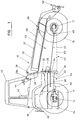
- a mobile materials handling implement 10 comprises front and rear axles 12, 14 and associated ground wheels 16, 17.
- An engine 18 and gear box assembly 20 are mounted between the rear wheels 17 and on top of the rigid and driven rear axle 14 with the transmission gear box 20 projecting forwardly from the engine, and with the cab 22 being located directly above the engine 18 and gear box assembly 20.
- Gear box 20 provides a so-called clutchless shuttle-type transmission of the kind currently used in agricultural tractor transmissions of the larger kind (eg of the order of 150 horse power) in which ratio engagement is controlled by a single lever operating solenoid valves to control multiple ratio-engage-disengage oil-immersed clutch plates, in which engagement and disengagement is controlled by oil flow.
- Such a gear box provides a regular variable ratio drive transmission offering tractor-type lugging power for duties which may be performed by the vehicle in addition to its loading operations, such duties being of the kind in which the vehicle's three-point hitch may be employed, such as routine tractor tasks including tillage operations, trailer haulage and the like.
- An important advantage of the provision of a non-torque-convertor transmission is that the loader is able to offer the farmer a vehicle having clear and useful alternative functions outside materials handling and loading, whereby the vehicle becomes a commercial option for a small scale farmer where it would not otherwise be so.
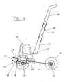
- Location of the engine 18 and gear box assembly 20 between (as viewed axially) the rear wheels and on top of the rear axle 14 facilitates easy access to the rear axle (as compared with rear-cantilevered engine machines) and allows for the provision of an agricultural hitching assembly 24 such as an implement three point hitch linkage (as shown in Fig 2) together with a power take-off shaft (not shown) on rear axle 14.
- an agricultural hitching assembly 24 such as an implement three point hitch linkage (as shown in Fig 2) together with a power take-off shaft (not shown) on rear axle 14.
- Attachment of a hitch hook 24 below rear axle 14 (and thus below engine 18) enables effective haulage of trailed implements without attendant geometrical hitching problems, in the manner of a conventional agricultural tractor, at speeds of up to 40kph.
- Three-point hitch linkage 25 comprises a single and central top link 27 and lower spaced draught links 29, these being connected to the rear axle assembly 14 in the conventional agricultural tractor manner.
- Conventional hydraulic control systems for the raising and lowering of draught links 29 on the basis of loads applied to top link 27 can be provided.
- the links have the conventional ball ends for hitching purposes.
- Fig 2 shows one 31 of a pair of hydraulic lift rams for draught links 29 together with the associated pto shaft 33.
- a telescopic boom 26 is mounted directly in front of cab 22 with the pivot point 28 of the boom being at a level whereby operator visibility is not significantly reduced.
- the boom 26 is a single and centrally-mounted telescopic boom (rather than a split boom provided at each side of the machine), and is located centrally with respect to the width of cab 22.
- the boom comprises telescopic boom portion 35, 37, 39 which are hydraulically extendable and retractable.
- the stability of the mobile materials handling implement 10 when using either the boom 26 at the front of the implement, or the three-point linkage 25 or the hitch-hook 24 at the rear, is increased by the provision for relative pivoting of the wheel axels and machine portions about a fore/aft pivot axis, whereby a greater equalisation of wheel loading is achieved on uneven ground.
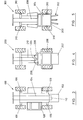
- a central horizontal pivot means 30 is provided and defines a pivot axis 31.
- the pivot means 30 permits angular movement between the front and rear axles 12, 14 about axis 31 and comprises two plates 32, and 34.
- One plate 34 is formed with a flange or lip 36 to engage with or "clip" onto the other plate 32.
- the plates 32, 34 are held together by means of a pin (not shown) which acts as the pivot pin.
- a suitable hard wearing material is provided between plates 32, 34 to reduce frictional forces therebetween.
- Plate 34 is formed with an aperture or relieved region 37 such that projecting components such as the oil pump 38 and front axle drive 40 which are mounted at this location on the engine/gear box assembly can project through the aperture without fouling any movably structures when pivoting occurs.
- FIG 1 Additional structures shown in Fig 1 include the rearwardly-mounted fan 40 on engine 18 which co-operates with a conventional engine cooling system (not shown).
- Cab 22 comprises a driver's control position including a driver's seat 42 and implement controls 44, these latter being at a height with respect to boom pivot 28 such that boom visibility through the transparent front wall of cab 22 is complete.
- Fig 1 also shows a rearwardly-offset position 28A for boom pivot 28 which can optionally be provided for the situation where maximum boom length is required, such as where a facility for stacking at particular heights is required. This is achieved by locating the pivot, effectively, within the cab envelope.
- the front wall transparent material of cab 22 is manufactured with a recessed region permitting the boom mounting to enter the recess without fouling the glass or plastic material.
- Fig 1 shows a front-wheel drive output shaft 46 connecting gear box 20 to a drive input connection 48 on front axle 12, universal joints being provided, of course.
- the drive output from gear box 20 to rear axle 14 is provided at 50.
- Boom 26 is provided with a mounting 52 for a bale fork or other materials handling device such as a bucket or grab.
- boom pivot 28 With regard to the overall structural integrity of implement 10, there is provided (but not shown in Fig 1 for clarity of illustration) a substantial support structure for boom pivot 28 whereby it is directly mounted on and connected to pivot plate 34 so as to be supported thereby for the application of boom loads to the vehicle frame and thus to the front and rear axle assemblies.
- pivot plate 34 With regard to the overall structural integrity of implement 10, there is provided (but not shown in Fig 1 for clarity of illustration) a substantial support structure for boom pivot 28 whereby it is directly mounted on and connected to pivot plate 34 so as to be supported thereby for the application of boom loads to the vehicle frame and thus to the front and rear axle assemblies.
- the fore/aft-connected axle assemblies which are nevertheless capable of relative pivotal movement (to accommodate ground irregularities) about axis 31.
- the recessed region in the front wall of cab 22 needs to be correspondingly enlarged to accommodate pivoting about axes 31.
- front portion of implement 10 including front axle 12, front wheel 16, and boom 26 and pivot plate 34 form a structurally integral unit which can pivot about axis 31 relative to the rearward portion of the implement, including cab 22, engine 18, rear axle 14, gear box 20 and pivot plate 32.
- implement 100 has a rear-cantilevered engine 102 and a rear-pivoted single central boom 104, wheel steering at the individual wheel locations 106 and a side-and-centrally-mounted cab 108, from which the view of loading operations is seriously compromised, in one direction, by boom 104.
- the latter is of relatively extended length due to its rear pivot at 110, but this advantage is substantially offset by the visibility implications of the location of cab 108.
- the location of engine 102 prevents the use of agricultural hitching arrangements.
- the implement 200 of Fig 4 has a rear-cantileved engine 202 with a central steering pivot at 204 controlled by rams 206 and a cab 208 positioned in front of engine 202.
- Boom 210 is mounted forwardly of pivot 204 and on the front portion of the implement and is therefore relatively short. Agricultural hitching arrangements are not possible due to the location of engine 202.
- the implement 300 has an agricultural hitch 302 rearwardly of engine 304 which is positioned below cab 306.
- Boom 308 is mounted directly in front of cab 306 so as to have adequate length.
- Cab 304 provides excellent visibility.
- Individual wheel steering axes 310 permit the requisite high manoeuvrability without the dynamic implications of the central pivot-steer arrangement of Fig 4.
- a hitch-hook (not shown) for trailed implements is provided below the rear axle.
- Machine 300 can carry out all normal functions of an agricultural tractor while offering the high loading performance of a dedicated materials handling implement having a telescopic boom.
- FIG 1 Another notable features of the embodiments include the radical departure from conventional machine layout for a vehicle of this kind.
- Fig 1 including the under-cab location of engine 18 with its forwardly-projecting transmission 20 which drives at 50 directly into back axle 14.
- the transmission structure is integral with the engine/back axle assembly, providing a structurally integral whole, which structure effectively terminates at its forward end at plate 32.
- Plate 32 is pivotally connected to plate 34.
- the latter is integral with what may be termed the forward chassis construction which is indicated in Fig 1 in broken dotted lines at 60, this structure linking front axle 12, plate 34 and the mounting including pivot 28 for boom 26, this assembly being, effectively a single structural unit identified at 62, which is pivotally connected to the rearward structural unit, likewise identified at 64.
- a further notable aspect of the construction arises from the location of engine 18 below cab 22, whereby the forward region 66 of vehicle/implement 10 is relieved of this presence of an engine (as would be the case if a conventional tractor lay out were adopted, and as a result, boom 26 can be provided with an extremely low lowered position, as indicated in Fig 1.
- a mobile self-propelled machine in which the single telescopic boom of the above embodiments is removed so as to produce, effectively, a mobile self-propelled platform which is capable of multi-functional use.
- the platform is provided with quick-attach and quick-detach mounting facilities whereby there can be mounted thereon selected ones of a group of sets of interchangeable agricultural apparatus offering various agricultural facilities.
- spray boom apparatus including a tank, liquid delivery means, a spray boom and associated spray nozzles.
- spray boom apparatus including a tank, liquid delivery means, a spray boom and associated spray nozzles.
- a similar change operation enables the platform to be converted to other uses such as a harvesting machine.
- a mobile self-propelled machine as defined in the accompanying claims directed to a mobile self-propelled single-telescopic-boom materials handling machine, but in which the features relating to the boom are deleted and replaced by mounting means for a series of two or more interchangeable agricultural operations facilities, such as spray boom apparatus.
- the mounting means is located generally forwardly of the vehicle cab and intermediate the cab and the forward steerable wheels of the vehicle, the mounting means being located generally at the same height as the fixed boom pivot for the telescopic loader facilities, and thus well above the centre line joining the vehicle wheels.
- machine option of the provision of a mobile platform with mountings for multi-functional use will be offered to a user not as a conversion option for a telescopic handler machine, but as a purchase option in respect of the original equipment. Additional features of this embodiment include the provision of a four-wheel steer function under the control of a steering control system in the vehicle cab.
Landscapes
- Engineering & Computer Science (AREA)
- Mechanical Engineering (AREA)
- Transportation (AREA)
- Structural Engineering (AREA)
- Chemical & Material Sciences (AREA)
- Combustion & Propulsion (AREA)
- Civil Engineering (AREA)
- Mining & Mineral Resources (AREA)
- General Engineering & Computer Science (AREA)
- Life Sciences & Earth Sciences (AREA)
- Geology (AREA)
- Agricultural Machines (AREA)
Applications Claiming Priority (4)
| Application Number | Priority Date | Filing Date | Title |
|---|---|---|---|
| GBGB9616239.1A GB9616239D0 (en) | 1996-08-01 | 1996-08-01 | Mobile materials handling machines |
| GB9616239 | 1996-08-01 | ||
| GB9702841A GB2316057B (en) | 1996-08-01 | 1997-02-12 | Mobile materials handling machines |
| GB9702841 | 1997-02-12 |
Publications (1)
| Publication Number | Publication Date |
|---|---|
| EP0823367A1 true EP0823367A1 (fr) | 1998-02-11 |
Family
ID=26309800
Family Applications (1)
| Application Number | Title | Priority Date | Filing Date |
|---|---|---|---|
| EP97305764A Withdrawn EP0823367A1 (fr) | 1996-08-01 | 1997-07-31 | Machine mobile de manutention |
Country Status (1)
| Country | Link |
|---|---|
| EP (1) | EP0823367A1 (fr) |
Cited By (3)
| Publication number | Priority date | Publication date | Assignee | Title |
|---|---|---|---|---|
| FR2765865A1 (fr) * | 1997-07-08 | 1999-01-15 | Jc Bamford Excavators Limited | Vehicule de manutention de materiaux |
| EP0987213A1 (fr) * | 1998-09-10 | 2000-03-22 | MERLO S.P.A. Industria Metalmeccanica | Véhicule utilisable comme un appareil de levage et un tracteur agricole |
| EP1052214A1 (fr) * | 1999-05-06 | 2000-11-15 | Merlo S.P.A. Industria Metalmeccanica | Véhicule pouvant être utilisé comme appareil de levage et tracteur agricole |
Citations (5)
| Publication number | Priority date | Publication date | Assignee | Title |
|---|---|---|---|---|
| US3888372A (en) * | 1973-06-01 | 1975-06-10 | Dynamic Ind | Front end loader device |
| WO1982003049A1 (fr) * | 1981-03-04 | 1982-09-16 | Inge Alexander Plymoth | Vehicule tous usages articule muni de roues |
| FR2567092A1 (fr) * | 1984-07-09 | 1986-01-10 | Driot Bernard | Tracto-pelle articule a usage agricole et de travaux publics |
| FR2614258A1 (fr) * | 1987-04-25 | 1988-10-28 | Fendt & Co Xaver | Vehicule porteur pour au moins un outil de travail frontal, en particulier, un tracteur agricole portant un outil de fauchage ou autres. |
| FR2621000A1 (fr) * | 1987-09-30 | 1989-03-31 | Dupont Andre | Engin porte-outils modulable |
-
1997
- 1997-07-31 EP EP97305764A patent/EP0823367A1/fr not_active Withdrawn
Patent Citations (5)
| Publication number | Priority date | Publication date | Assignee | Title |
|---|---|---|---|---|
| US3888372A (en) * | 1973-06-01 | 1975-06-10 | Dynamic Ind | Front end loader device |
| WO1982003049A1 (fr) * | 1981-03-04 | 1982-09-16 | Inge Alexander Plymoth | Vehicule tous usages articule muni de roues |
| FR2567092A1 (fr) * | 1984-07-09 | 1986-01-10 | Driot Bernard | Tracto-pelle articule a usage agricole et de travaux publics |
| FR2614258A1 (fr) * | 1987-04-25 | 1988-10-28 | Fendt & Co Xaver | Vehicule porteur pour au moins un outil de travail frontal, en particulier, un tracteur agricole portant un outil de fauchage ou autres. |
| FR2621000A1 (fr) * | 1987-09-30 | 1989-03-31 | Dupont Andre | Engin porte-outils modulable |
Cited By (5)
| Publication number | Priority date | Publication date | Assignee | Title |
|---|---|---|---|---|
| FR2765865A1 (fr) * | 1997-07-08 | 1999-01-15 | Jc Bamford Excavators Limited | Vehicule de manutention de materiaux |
| US6439827B1 (en) | 1997-07-08 | 2002-08-27 | J C Bamford Excavators Limited | Load handling vehicle |
| US6390764B1 (en) | 1998-09-09 | 2002-05-21 | Merlo Spa Industria Metalmeccanica | Vehicle operable as both a lifting machine and an agricultural tractor |
| EP0987213A1 (fr) * | 1998-09-10 | 2000-03-22 | MERLO S.P.A. Industria Metalmeccanica | Véhicule utilisable comme un appareil de levage et un tracteur agricole |
| EP1052214A1 (fr) * | 1999-05-06 | 2000-11-15 | Merlo S.P.A. Industria Metalmeccanica | Véhicule pouvant être utilisé comme appareil de levage et tracteur agricole |
Similar Documents
| Publication | Publication Date | Title |
|---|---|---|
| US5706901A (en) | Swivel hitch adaptable for use with either a tractor drawbar or two-point hitch | |
| US5423394A (en) | Three point hitch for hummer truck and other vehicles | |
| US4363374A (en) | Tractor | |
| US6390764B1 (en) | Vehicle operable as both a lifting machine and an agricultural tractor | |
| CA2307926C (fr) | Tracteur agricole multifonctionnel autopropulse | |
| US4693331A (en) | Tractor boom | |
| US11597451B2 (en) | Multifunctional traction or carrier vehicle | |
| US4585084A (en) | Agricultural tractor | |
| US5823270A (en) | Steerable implement hitch | |
| KR20170035163A (ko) | 360도 회전 가능한 굴절 아암을 구비한 농업용 트랙터 | |
| US4523656A (en) | Tractor for agricultural purposes | |
| US4860843A (en) | Pulling or loading vehicle with free space between the rear wheels | |
| EP0823367A1 (fr) | Machine mobile de manutention | |
| GB2316057A (en) | Vehicle with a single telescopic boom and a rear hitch | |
| WO1984001336A1 (fr) | Tracteur agricole | |
| EP0136910A2 (fr) | Tracteurs agricoles | |
| EP1182925B1 (fr) | Pulverisateur a usage agricole | |
| US5964078A (en) | Multiple implement tow bar assembly | |
| EP1401255B1 (fr) | Tracteur muni d'une boule d'attelage amovible | |
| US20230354731A1 (en) | Agricultural vehicle combination | |
| Bavendiek et al. | Selected Machine Examples | |
| CA1178308A (fr) | Vehicule polyvalent | |
| US3923322A (en) | Tractor hitch adapter | |
| CN218702713U (zh) | 一种传动机构及四轮微型耕作设备 | |
| GB2128147A (en) | Agricultural tractor |
Legal Events
| Date | Code | Title | Description |
|---|---|---|---|
| PUAI | Public reference made under article 153(3) epc to a published international application that has entered the european phase |
Free format text: ORIGINAL CODE: 0009012 |
|
| AK | Designated contracting states |
Kind code of ref document: A1 Designated state(s): DE FR GB IT |
|
| AX | Request for extension of the european patent |
Free format text: AL;LT;LV;RO;SI |
|
| 17P | Request for examination filed |
Effective date: 19980811 |
|
| AKX | Designation fees paid |
Free format text: DE FR GB IT |
|
| RBV | Designated contracting states (corrected) |
Designated state(s): DE FR GB IT |
|
| 17Q | First examination report despatched |
Effective date: 19991122 |
|
| STAA | Information on the status of an ep patent application or granted ep patent |
Free format text: STATUS: THE APPLICATION IS DEEMED TO BE WITHDRAWN |
|
| 18D | Application deemed to be withdrawn |
Effective date: 20000603 |