EP0822650A2 - Appareil de commande pour un moteur sans balai - Google Patents
Appareil de commande pour un moteur sans balai Download PDFInfo
- Publication number
- EP0822650A2 EP0822650A2 EP97305843A EP97305843A EP0822650A2 EP 0822650 A2 EP0822650 A2 EP 0822650A2 EP 97305843 A EP97305843 A EP 97305843A EP 97305843 A EP97305843 A EP 97305843A EP 0822650 A2 EP0822650 A2 EP 0822650A2
- Authority
- EP
- European Patent Office
- Prior art keywords
- phase
- current
- switching means
- rate
- state
- Prior art date
- Legal status (The legal status is an assumption and is not a legal conclusion. Google has not performed a legal analysis and makes no representation as to the accuracy of the status listed.)
- Granted
Links
Images


Classifications
-
- H—ELECTRICITY
- H02—GENERATION; CONVERSION OR DISTRIBUTION OF ELECTRIC POWER
- H02P—CONTROL OR REGULATION OF ELECTRIC MOTORS, ELECTRIC GENERATORS OR DYNAMO-ELECTRIC CONVERTERS; CONTROLLING TRANSFORMERS, REACTORS OR CHOKE COILS
- H02P6/00—Arrangements for controlling synchronous motors or other dynamo-electric motors using electronic commutation dependent on the rotor position; Electronic commutators therefor
- H02P6/14—Electronic commutators
-
- H—ELECTRICITY
- H02—GENERATION; CONVERSION OR DISTRIBUTION OF ELECTRIC POWER
- H02P—CONTROL OR REGULATION OF ELECTRIC MOTORS, ELECTRIC GENERATORS OR DYNAMO-ELECTRIC CONVERTERS; CONTROLLING TRANSFORMERS, REACTORS OR CHOKE COILS
- H02P6/00—Arrangements for controlling synchronous motors or other dynamo-electric motors using electronic commutation dependent on the rotor position; Electronic commutators therefor
- H02P6/08—Arrangements for controlling the speed or torque of a single motor
- H02P6/085—Arrangements for controlling the speed or torque of a single motor in a bridge configuration
Definitions
- This invention relates to a control strategy for an electric motor, and is especially suited to the control of brushless direct current motors.
- Brushless direct current (BLDC) motors offer an electric motor which has the advantages of simple operation, high speed operation and increased operational life when compared to equivalent sized brushed electric motors by virtue of the elimination of the commutation and bush gear.
- a rotor In a typical BLDC motor, a rotor is rotatably mounted inside a stator.
- the stator has a plurality of protruding elements, each element being provided with a coil winding, and the rotor has a plurality of poles.
- the coil windings are connected together in sets, with each set of connected windings defining a phase winding.
- the phase windings are then connected together at a star point.
- at least three, or possibly more, phases are provided.
- Energising the phases by applying a voltage across them causes the rotor to rotate so as to align with the magnetic flux portion generated by the energised windings.
- the phases in order to control the direction and speed of rotation of the rotor, the phases must be excited in a controlled sequence using a control strategy.
- the control strategy of the motor is arranged so that at any one time current is flowing in two of the phases (the phases are energised), whilst no current flows in the third phase (the neutral phase).
- the phases are energised
- the neutral phase is switched under the influence of the control strategy to become the neutral phase, and, simultaneously, the neutral phase is switched to carry current. This event is known as commutation.
- each of the phase windings is connected to a positive voltage supply through a first switching means, which is usually a transistor in parallel with a diode, and to a less positive voltage supply through a second switching means again usually a transistor in parallel with a diode. Switching on of a transistor enables current to flow through it to the phase winding from the voltage supply, and switching off the transistor isolates the phase winding from the voltage supply.
- a disadvantage with the method of controlling a motor described hereinbefore is that when a phase which is carrying a current is switched to become the phase which carries no current (i.e. commutation causes the phase to switch from an energised state to a neutral state), a transient drop in current is produced in one of the other phases. This transient results in a transient drop in torque and in addition generates unwanted acoustic noise.
- the transient originates from the attempt to enforce fast changes of current in the inductive load presented by the motor windings.
- the current in a first phase which will become the neutral phase is decreasing.
- the current in a second phase which was the neutral phase is increasing.
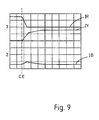
- the current in the first phase falls towards zero at a much greater rate than the current increases in the second phase. It is this difference in the two rates of change of current flow that produces the transient drop in current in the third phase. This is shown in Figure 9.
- a control apparatus for controlling a brushless motor in which a plurality of motor phases are connected in a bridge, each phase having a top switching means provided between a phase winding and a positive voltage supply, and a bottom switching means provided between the phase winding and a less positive voltage supply, characterised in that, following commutation: when the current flowing in a first phase is decaying towards zero and the current in a second phase is rising from zero, the switching means are operative between a state in which the current flowing in the first phase is caused to decay at a first rate, and another state in which the current flowing in the first phase is caused to decay at a second rate which is lower than the first rate, whereby the overall rate of decay of the current can be controlled within given values.
- the value of the current in the phase which is becoming the neutral phase can be controlled.
- the duration of time in which the switching means are in the first and second state following commutation may be varied, and most preferably, the duration of time in the first and second states is chosen so that the rate of decay of the current in the first phase substantially matches the rate of rise of the current in the second phase. This has the advantage of substantially eliminating the transient which would occur if the rate of fall and rate of rise of the currents were different.
- the switching means may be operated to form a zero volt loop around the bridge whereby the first phase winding forms a part of a low impedance loop around the bridge and the current drawn by the winding is in the same sense as the current drawn prior to commutation.
- the switching means may be operated to form around the bridge a negative volt loop whereby the first phase winding draws current from the opposite supply voltage to that from which current was drawn by the phase prior to commutation i.e. the current stays in the same sense, but is opposed by the applied voltage.
- Preferably three motor phases are connected in a star formation within a bridge.
- the switching means may each comprise a transistor connected in parallel with a diode.
- the switch means can then be operated by applying a suitable current signal to the base of the transistor.
- more than one transistor may be provided for each switching means.
- the top switching means may be operated by applying a first pulse width modulated signal and the bottom switching means may be operated by applying a respective second pulse width modulated signal which is in anti-phase to the first signal.
- the transistors on all three phases of the motor are undergoing pulse width modulation. This differs from the motor control method known in the art in which the top and bottom switching means in the neutral phase are not modulated.
- An interlock delay may also be provided to prevent current shoot through due to the finite switching time of the transistors.
- the PWM waveforms applied to each of the switching means may have the same phase, and may be centre-aligned with one another to minimise electrical noise.
- the PWM waveforms applied to each phase may further be chosen so that, during operation of the motor, the net voltage applied across one of the phases is of an arbitrary constant value, whilst the net voltage applied across the remaining two phases is respectively greater than and less than the arbitrary value by a variable amount x.
- x By altering the value of x, the speed of the motor can be controlled.
- This method of motor control has the advantage that the switching means are automatically switched to be in the first state and second state following commutation during every pulse width modulation period, whilst maintaining the condition that a current flows in only two of the three phases, at any time.
- the PWM waveforms may be varied following a commutation so as to vary the ratio of the time spent in the zero volt loop state and the time spent in the negative volt loop state.
- the position at which commutation is initiated may be varied.
- the commutation points may be advanced spatially in order to compensate for an increased duration of commutation which arises from slowing the rate of current decay.
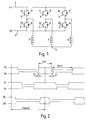
- a motor comprising a rotor which is rotatably mounted within a stator is provided with three phase windings (R, Y, B).
- Each phase winding is connected to a positive voltage supply line 1 of value V volts via a top switching means (R T ,Y T ,B T ), and to a zero volts supply line 2 via a bottom switching means (R B ,Y B ,B B ).
- the switching means each comprise a transistor 3 connected in parallel with a diode 4.
- Each phase winding is assumed to be identical, and, in particular, to have the same resistance.
- the phases are connected at a star point 5.
- the six transistors are operated by applying a pulse width modulated signal to their respective gates and the top and bottom transistors are operated in anti-phase.
- the signals are also centre-aligned and have the same period PWMP. This is shown in Figure 2.
- An interlock delay ID is also incorporated to avoid current shoot-through.
- the average voltage applied to the motor phase is given by: TOP_HIGH_TIME TOP_HIGH_TIME + BOTTOM_HIGH_TIME xBridge_Supply_Voltage where the bridge supply voltage is the voltage of the positive supply line 1, and TOP_HIGH_TIME and BOTTOM_HIGH_TIME are denoted by THT and BHT in Figure 2 of the drawings.
- the pulse width modulation signals applied to each of the transistors are chosen so that a net current only flows in two of the three phases, with zero current flowing in the third phase.
- Figure 3 shows the net voltages applied to the three phases for the case when no torque is to be generated. Identical (but phase shifted) first and second waveforms are applied to the top and bottom transistors in each phase of the motor so that the net voltage applied to each phase winding has the same arbitrary value. As shown in Figure 3 this value is chosen to lie midway between the positive and ground voltage supplies, i.e. 1 ⁇ 2V. The voltage at the star point will therefore also be 1 ⁇ 2V, and no current will flow in any of the phase windings.
- Figure 4 shows an example of the current flowing in the windings using this method of control when the motor is producing torque.
- the pulse width modulation duties of the signals applied to the top and bottom transistors are varied from those used when the motor is stationary so that the net voltage applied to the red phase is now (1 ⁇ 2 V+ x ) , the net voltage applied to the blue phase remains 1 ⁇ 2V, and the net voltage applied to the yellow phase is now (1 ⁇ 2 V- x ).
- Current will now flow into the red phase and out of the yellow phase. Because the resistance of each phase has been assumed to be identical, the voltage at the star point is still 1 ⁇ 2V, and so no net current flows in the blue phase. Hence, the requirement for driving a DC brushless motor is met.
- the value of the variable voltage x is chosen in response to a motor current demand, and increasing the magnitude of x will cause the current flowing in the windings of the motor to increase.
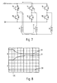
- Figure 7 shows the second state in which the transistors in the phases are now in the opposite state to that in Figure 6.
- This arrangement of switches comprises a zero volt loop.
- the red phase winding now forms a part of a low impedance loop and the current falls slowly. It will, however, be readily appreciated that for a commutation in which a phase carrying a negative current becomes the neutral phase, the first state will constitute a zero volt loop and the second state will constitute a negative volt loop, i.e. the two states will be reversed.
- this method inherently switches the motor phase windings between a zero volt loop and a negative volt loop, controlling the rate of fall of the current.
- the rate of rise of the motor drive current in the phase is more closely matched to the rate of fall of current in an associated phase, thus torque ripple and noise is eliminated.
- a voltage other than 1 ⁇ 2V is applied to the neutral phase for a predefined period after commutation, to give a predetermined ratio of duration of negative to zero volt loop, to control the rate of decay of current in that phase.
- the transistors on the neutral phase are returned to a state which applied a voltage of 1 ⁇ 2V to the phase winding by pulse width modulation of the top and bottom transistors, or the top and bottom transistors can both be switched off to ensure that zero current flows in the neutral phase.
- the refined method differs from the prior art in that the state of the phases is switched between a zero volt loop and a negative volt loop immediately following commutation, although either side of a commutation event the method controls the motor in the manner known in the prior art.
- the negative volt loop may be invoked for, say 75% of the modulation period, and the zero volt loop may be invoked for the remaining 25% of the time. It is notable, however, that the zero volt loop is invoked in different ways according to the sign of the current in the phase immediately before commutation. If the current is flowing into the motor phase before commutation, the zero volt loop is invoked by switching the top transistor on. If the current is flowing out of the motor phase before commutation, then the zero volt loop is invoked by switching the bottom device on. Since commutations occur alternately as each of these two cases, the particular PWM duty to give, say, a 75%/25% negative/zero volt loop ratio is individually calculated according to the type of commutation.
- Figure 8 shows a set of measured phase currents I R ,I Y ,I B obtained using the method of the present invention during a commutation event CE.
- the transient in torque has been eliminated by reducing the rate of fall of current in the phase.
- the position at which commutations occur may be advanced in time.
- the amount of advance applied will depend on the motors electrical time constant. Advancing commutation is useful in combination with the method described herein before as the slowing of the rate of decay of current in the phase which becomes the neutral phase results in a small loss of motor torque as it effectively increases the duration of commutation. Advancing the commutation point compensates for this slower commutation and allows motor torque to be regained.
- the time required for commutation is dependent on motor electrical time constant, which is fixed, the amount of advance required may also be a fixed arbitrary value.
Applications Claiming Priority (2)
| Application Number | Priority Date | Filing Date | Title |
|---|---|---|---|
| GB9616355 | 1996-08-03 | ||
| GBGB9616355.5A GB9616355D0 (en) | 1996-08-03 | 1996-08-03 | Improvements in and relating to motors |
Publications (3)
| Publication Number | Publication Date |
|---|---|
| EP0822650A2 true EP0822650A2 (fr) | 1998-02-04 |
| EP0822650A3 EP0822650A3 (fr) | 1998-07-29 |
| EP0822650B1 EP0822650B1 (fr) | 2006-10-04 |
Family
ID=10797984
Family Applications (1)
| Application Number | Title | Priority Date | Filing Date |
|---|---|---|---|
| EP97305843A Expired - Lifetime EP0822650B1 (fr) | 1996-08-03 | 1997-08-01 | Appareil de commande pour un moteur sans balai |
Country Status (4)
| Country | Link |
|---|---|
| US (1) | US5821714A (fr) |
| EP (1) | EP0822650B1 (fr) |
| DE (1) | DE69736761T2 (fr) |
| GB (1) | GB9616355D0 (fr) |
Cited By (3)
| Publication number | Priority date | Publication date | Assignee | Title |
|---|---|---|---|---|
| EP0966093A2 (fr) * | 1998-06-17 | 1999-12-22 | Delphi Technologies, Inc. | Procéde de réglage pour moteur à courant continu sans balais avec bruit de commutation réduit |
| US6452349B1 (en) | 1998-11-09 | 2002-09-17 | Papst-Motoren Gmbh & Co. Kg | Electronically commutated motor |
| EP2461477A3 (fr) * | 2010-12-03 | 2017-12-06 | Conti Temic microelectronic GmbH | Procédé de commutation pour un moteur sans balais |
Families Citing this family (4)
| Publication number | Priority date | Publication date | Assignee | Title |
|---|---|---|---|---|
| US5955851A (en) * | 1998-01-28 | 1999-09-21 | Harris Corporation | Brushless dc motor PWM scheme for quiet commutation |
| WO2001020161A1 (fr) * | 1999-09-15 | 2001-03-22 | Knite, Inc. | Circuits electroniques pour dispositifs de production de plasma |
| JP2001268879A (ja) * | 2000-03-22 | 2001-09-28 | Nsk Ltd | ブラシレスモータ及びその駆動制御装置 |
| US6424107B1 (en) | 2000-09-06 | 2002-07-23 | Trw Inc. | Apparatus and method for controlling an electric motor |
Citations (3)
| Publication number | Priority date | Publication date | Assignee | Title |
|---|---|---|---|---|
| EP0084156A1 (fr) * | 1981-12-23 | 1983-07-27 | Papst-Motoren GmbH & Co. KG | Moteur à courant continu sans collecteur |
| DE3710509C1 (en) * | 1987-03-30 | 1988-11-03 | Philips Patentverwaltung | Method for commutating a DC motor |
| US4988939A (en) * | 1989-08-04 | 1991-01-29 | Thor Technology Corporation | Electric motor with variable commutation delay |
Family Cites Families (3)
| Publication number | Priority date | Publication date | Assignee | Title |
|---|---|---|---|---|
| US4164697A (en) * | 1976-04-08 | 1979-08-14 | Texas Instruments Incorporated | Method and system for squelching decaying current in motor phases |
| DE3610253A1 (de) * | 1986-03-26 | 1987-10-08 | Sgs Halbleiterbauelemente Gmbh | Steuerschaltung fuer einen kommutatorlosen gleichstrommotor |
| US5191269A (en) * | 1991-10-10 | 1993-03-02 | Sgs-Thomson Microelectronics, Inc. | Brushless direct current motor with minimized current ripple and method |
-
1996
- 1996-08-03 GB GBGB9616355.5A patent/GB9616355D0/en active Pending
-
1997
- 1997-08-01 DE DE69736761T patent/DE69736761T2/de not_active Expired - Fee Related
- 1997-08-01 EP EP97305843A patent/EP0822650B1/fr not_active Expired - Lifetime
- 1997-08-01 US US08/904,857 patent/US5821714A/en not_active Expired - Fee Related
Patent Citations (3)
| Publication number | Priority date | Publication date | Assignee | Title |
|---|---|---|---|---|
| EP0084156A1 (fr) * | 1981-12-23 | 1983-07-27 | Papst-Motoren GmbH & Co. KG | Moteur à courant continu sans collecteur |
| DE3710509C1 (en) * | 1987-03-30 | 1988-11-03 | Philips Patentverwaltung | Method for commutating a DC motor |
| US4988939A (en) * | 1989-08-04 | 1991-01-29 | Thor Technology Corporation | Electric motor with variable commutation delay |
Cited By (4)
| Publication number | Priority date | Publication date | Assignee | Title |
|---|---|---|---|---|
| EP0966093A2 (fr) * | 1998-06-17 | 1999-12-22 | Delphi Technologies, Inc. | Procéde de réglage pour moteur à courant continu sans balais avec bruit de commutation réduit |
| EP0966093A3 (fr) * | 1998-06-17 | 2002-04-17 | Delphi Technologies, Inc. | Procéde de réglage pour moteur à courant continu sans balais avec bruit de commutation réduit |
| US6452349B1 (en) | 1998-11-09 | 2002-09-17 | Papst-Motoren Gmbh & Co. Kg | Electronically commutated motor |
| EP2461477A3 (fr) * | 2010-12-03 | 2017-12-06 | Conti Temic microelectronic GmbH | Procédé de commutation pour un moteur sans balais |
Also Published As
| Publication number | Publication date |
|---|---|
| EP0822650B1 (fr) | 2006-10-04 |
| GB9616355D0 (en) | 1996-09-11 |
| EP0822650A3 (fr) | 1998-07-29 |
| US5821714A (en) | 1998-10-13 |
| DE69736761T2 (de) | 2007-08-02 |
| DE69736761D1 (de) | 2006-11-16 |
Similar Documents
| Publication | Publication Date | Title |
|---|---|---|
| US5929590A (en) | Method and apparatus for implementing sensorless control of a switched reluctance machine | |
| US7554279B2 (en) | Method for operating an electronically commutated motor, and motor for carrying out a method such as this | |
| US5166591A (en) | Current chopping strategy for generating action in switched reluctance machines | |
| US6087799A (en) | Switching circuit for a reluctance machine | |
| US5923142A (en) | Low cost drive for switched reluctance motor with DC-assisted excitation | |
| KR100600540B1 (ko) | 스위치드 릴럭턴스 장치의 구동장치 및 그 구동방법 | |
| US5208518A (en) | DC-DC boost converter for spindle motor control | |
| US5015927A (en) | Electric motor with regeneration current commutation | |
| US20020158600A1 (en) | Brushless-motor driver in PWM mode | |
| US6137256A (en) | Soft turn-off controller for switched reluctance machines | |
| JPH08140398A (ja) | モータ制御装置 | |
| JPH0236788A (ja) | ブラシレス電動モータの制御方法とその制御回路 | |
| GB1587795A (en) | Stepping motor drive method and apparatus | |
| US5821714A (en) | Improvements in and relating to motors | |
| JPH0236789A (ja) | ブラシレス電動モータの制御方法とその制御回路 | |
| JP2002534952A (ja) | 多相直流電動機駆動装置 | |
| JP2003018890A (ja) | スイッチトリラクタンス駆動システムに関する制御方法 | |
| EP0653833B1 (fr) | Moteur électrique sans balais et méthode pour commander le moteur | |
| EP1958324A2 (fr) | Dispositif d'entrainement pour moteur sans balais comportant un dispositif d'entrainement et un moteur sans balais et procede pour l'entrainement d'un moteur | |
| US6906481B1 (en) | Power sharing high frequency motor drive modular system | |
| WO2013110501A2 (fr) | Procédé pour commander un moteur bldc | |
| US6838841B2 (en) | Method for controlling an electronically commutated DC motor | |
| US7388347B2 (en) | Method and inverter for controlling a direct current motor | |
| JP3286052B2 (ja) | ブラシレスモータの制御回路 | |
| JP3315792B2 (ja) | ブラシレスモータの制御回路 |
Legal Events
| Date | Code | Title | Description |
|---|---|---|---|
| PUAI | Public reference made under article 153(3) epc to a published international application that has entered the european phase |
Free format text: ORIGINAL CODE: 0009012 |
|
| AK | Designated contracting states |
Kind code of ref document: A2 Designated state(s): DE FR GB IT |
|
| AX | Request for extension of the european patent |
Free format text: AL;LT;LV;RO;SI |
|
| PUAL | Search report despatched |
Free format text: ORIGINAL CODE: 0009013 |
|
| AK | Designated contracting states |
Kind code of ref document: A3 Designated state(s): AT BE CH DE DK ES FI FR GB GR IE IT LI LU MC NL PT SE |
|
| AX | Request for extension of the european patent |
Free format text: AL;LT;LV;RO;SI |
|
| 17P | Request for examination filed |
Effective date: 19981130 |
|
| AKX | Designation fees paid |
Free format text: DE FR GB IT |
|
| RBV | Designated contracting states (corrected) |
Designated state(s): DE FR GB IT |
|
| RAP1 | Party data changed (applicant data changed or rights of an application transferred) |
Owner name: LUCAS INDUSTRIES LIMITED |
|
| 17Q | First examination report despatched |
Effective date: 20001025 |
|
| RAP1 | Party data changed (applicant data changed or rights of an application transferred) |
Owner name: LUCAS INDUSTRIES LIMITED |
|
| GRAP | Despatch of communication of intention to grant a patent |
Free format text: ORIGINAL CODE: EPIDOSNIGR1 |
|
| GRAS | Grant fee paid |
Free format text: ORIGINAL CODE: EPIDOSNIGR3 |
|
| RAP1 | Party data changed (applicant data changed or rights of an application transferred) |
Owner name: LUCAS INDUSTRIES LIMITED |
|
| GRAA | (expected) grant |
Free format text: ORIGINAL CODE: 0009210 |
|
| AK | Designated contracting states |
Kind code of ref document: B1 Designated state(s): DE FR GB IT |
|
| PG25 | Lapsed in a contracting state [announced via postgrant information from national office to epo] |
Ref country code: IT Free format text: LAPSE BECAUSE OF FAILURE TO SUBMIT A TRANSLATION OF THE DESCRIPTION OR TO PAY THE FEE WITHIN THE PRE;WARNING: LAPSES OF ITALIAN PATENTS WITH EFFECTIVE DATE BEFORE 2007 MAY HAVE OCCURRED AT ANY TIME BEFORE 2007. THE CORRECT EFFECTIVE DATE MAY BE DIFFERENT FROM THE ONE RECORDED.SCRIBED TIME-LIMIT Effective date: 20061004 |
|
| REG | Reference to a national code |
Ref country code: GB Ref legal event code: FG4D |
|
| REF | Corresponds to: |
Ref document number: 69736761 Country of ref document: DE Date of ref document: 20061116 Kind code of ref document: P |
|
| ET | Fr: translation filed | ||
| PLBE | No opposition filed within time limit |
Free format text: ORIGINAL CODE: 0009261 |
|
| STAA | Information on the status of an ep patent application or granted ep patent |
Free format text: STATUS: NO OPPOSITION FILED WITHIN TIME LIMIT |
|
| 26N | No opposition filed |
Effective date: 20070705 |
|
| PGFP | Annual fee paid to national office [announced via postgrant information from national office to epo] |
Ref country code: GB Payment date: 20070705 Year of fee payment: 11 |
|
| PGFP | Annual fee paid to national office [announced via postgrant information from national office to epo] |
Ref country code: IT Payment date: 20070814 Year of fee payment: 11 |
|
| PGFP | Annual fee paid to national office [announced via postgrant information from national office to epo] |
Ref country code: FR Payment date: 20070803 Year of fee payment: 11 |
|
| PGFP | Annual fee paid to national office [announced via postgrant information from national office to epo] |
Ref country code: DE Payment date: 20080829 Year of fee payment: 12 |
|
| GBPC | Gb: european patent ceased through non-payment of renewal fee |
Effective date: 20080801 |
|
| REG | Reference to a national code |
Ref country code: FR Ref legal event code: ST Effective date: 20090430 |
|
| PG25 | Lapsed in a contracting state [announced via postgrant information from national office to epo] |
Ref country code: IT Free format text: LAPSE BECAUSE OF NON-PAYMENT OF DUE FEES Effective date: 20080801 Ref country code: FR Free format text: LAPSE BECAUSE OF NON-PAYMENT OF DUE FEES Effective date: 20080901 |
|
| PG25 | Lapsed in a contracting state [announced via postgrant information from national office to epo] |
Ref country code: GB Free format text: LAPSE BECAUSE OF NON-PAYMENT OF DUE FEES Effective date: 20080801 |
|
| PG25 | Lapsed in a contracting state [announced via postgrant information from national office to epo] |
Ref country code: DE Free format text: LAPSE BECAUSE OF NON-PAYMENT OF DUE FEES Effective date: 20100302 |