EP0822030A1 - Vorrichtung und Verfahren zum Einstellen von Werkstückträgern - Google Patents
Vorrichtung und Verfahren zum Einstellen von Werkstückträgern Download PDFInfo
- Publication number
- EP0822030A1 EP0822030A1 EP96120965A EP96120965A EP0822030A1 EP 0822030 A1 EP0822030 A1 EP 0822030A1 EP 96120965 A EP96120965 A EP 96120965A EP 96120965 A EP96120965 A EP 96120965A EP 0822030 A1 EP0822030 A1 EP 0822030A1
- Authority
- EP
- European Patent Office
- Prior art keywords
- fastening bar
- holding members
- respect
- pallet
- location
- Prior art date
- Legal status (The legal status is an assumption and is not a legal conclusion. Google has not performed a legal analysis and makes no representation as to the accuracy of the status listed.)
- Granted
Links
Images


Classifications
-
- B—PERFORMING OPERATIONS; TRANSPORTING
- B23—MACHINE TOOLS; METAL-WORKING NOT OTHERWISE PROVIDED FOR
- B23Q—DETAILS, COMPONENTS, OR ACCESSORIES FOR MACHINE TOOLS, e.g. ARRANGEMENTS FOR COPYING OR CONTROLLING; MACHINE TOOLS IN GENERAL CHARACTERISED BY THE CONSTRUCTION OF PARTICULAR DETAILS OR COMPONENTS; COMBINATIONS OR ASSOCIATIONS OF METAL-WORKING MACHINES, NOT DIRECTED TO A PARTICULAR RESULT
- B23Q7/00—Arrangements for handling work specially combined with or arranged in, or specially adapted for use in connection with, machine tools, e.g. for conveying, loading, positioning, discharging, sorting
- B23Q7/14—Arrangements for handling work specially combined with or arranged in, or specially adapted for use in connection with, machine tools, e.g. for conveying, loading, positioning, discharging, sorting co-ordinated in production lines
- B23Q7/1426—Arrangements for handling work specially combined with or arranged in, or specially adapted for use in connection with, machine tools, e.g. for conveying, loading, positioning, discharging, sorting co-ordinated in production lines with work holders not rigidly fixed to the transport devices
-
- H—ELECTRICITY
- H02—GENERATION; CONVERSION OR DISTRIBUTION OF ELECTRIC POWER
- H02K—DYNAMO-ELECTRIC MACHINES
- H02K15/00—Methods or apparatus specially adapted for manufacturing, assembling, maintaining or repairing of dynamo-electric machines
Definitions
- the present invention relates to an adjustment apparatus of workpiece carriers of the type having variable distance holding members for workpieces of different dimensions in automatic production lines.
- the invention relates also to a corresponding adjustment method.
- each pallet downstream from a starting station where it receives a workpiece, moves on a conveyor which carries it selectively through the workstations.
- the workpiece is offered to a machine which picks it up away from the pallet, works on it and then leaves it again on the pallet which continues moving.
- the workpieces are armatures of electric motors, comprising longitudinal grooves in which a wire must be wound
- winding machines are known which are capable of working with pieces in a large range of dimensions, different both in their diameter and in their length.
- the pallets in this case, shall offer the armatures to the machine centred and held by variable distance supports adjusted as a function of their length.
- a pallet for armatures having two V shaped supports which hold the ends of an armature shaft.
- the V shaped supports are slidingly mounted on a guide integral to the pallet, on board of which means for the translation of the supports on the guide are provided for, such as an endless screw automatically operable in an adjustment station.
- Locking devices are provided for on the pallet, preventing the support from translating on the guide until, in the adjustment station, actuating means act on the locking means freeing the supports and allowing that motorised means can act on the means for the translation, thus causing the supports to slide on the guide up to a new position.
- All the embodiments described comprise an adjustment apparatus having heads engaging with the means for the translation on board of the pallet and with the locking means, also mounted on the pallet. Therefore, besides the adjustment station, mechanically complex pallets must be provided for, as well as means for actuating the locking means.
- the supports comprise a V shaped plate engaging with a couple of parallel guides on which the supports can slide moving towards and away from each other when not blocked by locking means.
- the adjustment apparatus has two horizontally and vertically translating heads capable of unlocking the support members and of moving them to a new location.
- a pallet having simpler structure and consisting substantially in a frame defining a central aperture.
- a T-shaped guide is mounted with which support members slidingly engage having V-shaped ends for a workpiece.
- Locking devices are provided for, which resiliently engage with the supports frictionally pushing them against the T guides.
- the supports can be automatically unlocked in order to slide on the guide.
- the adjustment apparatus comprises an actuating unit provided below the pallet and acting on the locking devices to keep them away from the guide, whereas a first couple of translating heads is provided for above the pallet pushing the holding supports along the guide up to a central reference position.
- the automatically adjustable pallets require necessarily the presence of unlocking devices of the locking means. Therefore, they need adjustment means of the position of the supports which are also able to free the supports from the locking means before translating them. This requires a complex structure both of the pallet and of the automatic adjustment means. Moreover, the existing pallets do not allow the automatic replacement of the support members, because they are slidingly mounted on the guides but cannot easily be moved away from them, unless manually.
- the holding supports are auto-locking on the guide and means for their automatic locking/unlocking with respect to the guides are not necessary.
- the displacement of the supports may also be carried out manually, after a rotation with respect to the fastening bar substantially without touching it before the next auto-locking at the new location. This characteristic allows for both a manual and automatic adjustment.
- the fact that the holding supports are physically separable from the fastening bar allows the fact that they can be automatically replaced with other arms or other supports members of different shape.
- an apparatus for the automatic adjustment of the distance between the holding members of a pallet, of the type comprising members supporting a workpiece connected to a fastening bar and allowing a movement in a plane transversal to said bar between a first auto-locking position on the fastening bar and a second position of free movement.
- the characteristic of the apparatus is that it comprises: gripping means for said holding members, means for moving said gripping means from said first to said second position, and means for translating parallelly to said fastening bar said means for moving.
- the movement of said holding members in the plane transversal to the fastening bar is a rotation with respect to the fastening bar between a first angular position and a second angular position, said means for moving said gripping means from said first to said second position, and back, allowing an angular rotation concentric to the rotation of said holding members.
- An adjustment method comprises the steps of:
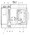
- an apparatus 1 for the adjustment of the distance between the holding members 2, or arms, of a pallet 3 is associated to an automatic conveyor transfer system of pallets 3 through many workstations, not shown.
- Apparatus 1 is in particular placed at a station 5, where each pallet 3, before receiving a workpiece, is identified by means of a coded sensor 6 integral to it.
- a platform 8 is raised by a cylinder 9 up to the pallet 3 which is centred by means of reference pins 7, shown in figure 8. Then, the platform 8 raises the pallet up to the adjustment apparatus described hereinafter.
- apparatus 1 comprises a head 10 having a gripper 11 suited to grip one of the holding members 2, or arms, of pallet 3, which are mounted in a auto-locking way on fastening bar 12, which is integral to pallet 3 itself.
- Head 10 is slidingly mounted on a first slide 13 having an internal actuator moving head 10 orthogonally to arms 2 in a plane transversal to fastening bar 12.
- First slide 13 can move with respect to a plate 14 following a path 15 defined by a groove 16.
- Plate 14 is mounted on a second slide 17, which moves horizontally, operated by an engine 18 by means of a belt and an endless screw 19, or, alternatively, by equivalent linear actuating means.
- a preferred embodiment of pallet 3 has fastening bar 12 (figures. 4-7) provided with a longitudinal cylindrical portion 20 having a flattening 21 suited to receive a graduated line 22.
- Arms 2 of pallet 1 have a free V-shaped end 23 capable of holding a shaft 24 of a workpiece 25, for example an armature of an electric motor, visible in a portion of the conveyor parallel to that comprising the adjustment station 5 and shown in figure 2, on the right.
- arms 2 At the end opposite to free end 23, arms 2 have a tubular open body 26, having an internal cylindrical housing 27 of the same diameter of cylindrical portion 20 of fastening bar 12.
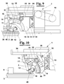
- each arm 2 with respect to fastening bar 12 occurs as follows. Starting from an auto-locked position on fastening bar 12 by means of a resilient tooth 28, holding arm 2, in order to be moved, must be rotated, as shown in figure 5, and must be orthogonally moved away, even slightly, from fastening bar 12, as shown in figure 6. In such position, arm 2 is completely released from fastening bar 12 and can be moved to another location of the bar, even without touching it, held by gripper 11.
- each holding arm 2 starting from the locked position (shown on the left), can be moved by gripper 11 to the free movement position (in the middle) and, after having reached the preferred location, can be moved and rotated inversely (on the right) and then auto-locked again on fastening bar 12.
- slide 13 follows a circular path 15 (fig. 1) with respect to plate 14, said path being defined by groove 16 shaped as a circular slot, concentric to the axis of the cylindrical portion of fastening bar 12 when the pallet is on platform 8.
- a carriage 30 engages with groove 16, integral to a portion of a curved rack 31, meshing with gear 32 integral to plate 14.
- a linear rack 33 integral to a third slide 34 is provided for, which can move horizontally with respect to an upper support 35.
- head 10 is in horizontal position and gripper 11 is lowered so as to grip arm 2, which is auto-locked on fastening bar 12 of the pallet.
- the movement of gripper 11, orthogonally to arm 2, is caused by the sliding of head 10 on first slide 13.
- third slide 34 With reference to figure 10, the movement of third slide 34 with respect to upper support 35 causes curved rack 31, through linear rack 33 and gear 32, to slide in groove 16, in a way which is similar, likewise the movement of an operator who wants manually obtain the same effect, to a hand rotating about its wrist, so that head 10 rotates about fastening bar 12 following path 15.
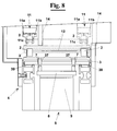
- FIG 8 The two opposite extreme locations of head 10 with respect to fastening bar 12 are shown in figure 8, where the pallet is illustrated both in lowered position on a conveyor belt 39, and in raised position, indicated with a dotted line.
- gripper 11 can move each arm 2 to whichever intermediate location, between the left (continuous line) and the right (dotted line) of fig. 8, according to the size of the workpiece held by the pallet.
- FIG 2 Also in figure 2 holes 37 of the pallet are shown, in which reference pins 7 of platform 8 engage. Moreover the two-portions 11a e 11b of gripper 11 are shown, which can approach each other while engaging their teeth 11c with recesses 38 laterally provided for on holding members and shown in figure 7.
- the adjustment method comprises a step in which the second slide 17 stops gripper 11 exactly at one of holding members 2, by means of an optical sensor 40, shown in figures 1, 9 and 10 and not described further because it is of commercially available known type.
- Sensor 40 detects the location of holding members 2 with respect to fastening bar 12 and communicates this to a control unit not shown. The latter compares the stored location with the actual location and operates motor 18, for example a step motor or equivalent linear actuator, causing the translation of second slide 17 up to said stored location, only if the stored location differs from the actual location.
- the direct comparison between the actual location and the stored location does not require, every time, the translation to a position of zero, with a first saving of time on the adjustment cycle.
- the presence of a sensor and the direct comparison allows for the fact that the translation of the holding members is not necessary when they are already in a location coinciding to the stored location, with a further saving of time on the cycle, because many pallets pass the adjustment station without that their holding members are touched.
Landscapes
- Engineering & Computer Science (AREA)
- Manufacturing & Machinery (AREA)
- Power Engineering (AREA)
- Mechanical Engineering (AREA)
- Automatic Assembly (AREA)
- Constituent Portions Of Griding Lathes, Driving, Sensing And Control (AREA)
- Encapsulation Of And Coatings For Semiconductor Or Solid State Devices (AREA)
- Control Of Position, Course, Altitude, Or Attitude Of Moving Bodies (AREA)
- Multi-Process Working Machines And Systems (AREA)
- General Factory Administration (AREA)
- Grinding Of Cylindrical And Plane Surfaces (AREA)
- Feeding Of Workpieces (AREA)
Priority Applications (1)
| Application Number | Priority Date | Filing Date | Title |
|---|---|---|---|
| SI9630658T SI0822030T1 (en) | 1996-07-26 | 1996-12-28 | Apparatus and method for the adjustment of workpiece carriers |
Applications Claiming Priority (2)
| Application Number | Priority Date | Filing Date | Title |
|---|---|---|---|
| IT96PI000037A IT1289296B1 (it) | 1996-07-26 | 1996-07-26 | Apparecchiatura e metodo di regolazione di attrezzature portapezzo mobili su linee di lavorazione automatica |
| ITPI960037 | 1996-07-26 |
Publications (2)
| Publication Number | Publication Date |
|---|---|
| EP0822030A1 true EP0822030A1 (de) | 1998-02-04 |
| EP0822030B1 EP0822030B1 (de) | 2003-12-10 |
Family
ID=11394030
Family Applications (1)
| Application Number | Title | Priority Date | Filing Date |
|---|---|---|---|
| EP96120965A Expired - Lifetime EP0822030B1 (de) | 1996-07-26 | 1996-12-28 | Vorrichtung und Verfahren zum Einstellen von Werkstückträgern |
Country Status (6)
| Country | Link |
|---|---|
| US (1) | US5984085A (de) |
| EP (1) | EP0822030B1 (de) |
| AT (1) | ATE255979T1 (de) |
| DE (1) | DE69631040T2 (de) |
| IT (1) | IT1289296B1 (de) |
| SI (1) | SI0822030T1 (de) |
Cited By (1)
| Publication number | Priority date | Publication date | Assignee | Title |
|---|---|---|---|---|
| EP1388391A1 (de) * | 2002-08-06 | 2004-02-11 | ATOP S.p.A. | Palette für den Transport von Armaturen von Elektromotoren in automatisierten Produktionslinien |
Families Citing this family (3)
| Publication number | Priority date | Publication date | Assignee | Title |
|---|---|---|---|---|
| DE19809515C2 (de) * | 1998-03-05 | 2002-10-31 | Daimler Chrysler Ag | Verfahren und Vorrichtung zum Applizieren von selbsthaftender Schutzfolie auf Karosserien |
| DE102015206983A1 (de) * | 2015-04-17 | 2016-10-20 | Kuka Systems Gmbh | Montageplattform |
| TWM575742U (zh) * | 2018-11-07 | 2019-03-21 | 達佛羅企業有限公司 | 可替換工件的加工裝置 |
Citations (3)
| Publication number | Priority date | Publication date | Assignee | Title |
|---|---|---|---|---|
| EP0348715A1 (de) | 1988-06-27 | 1990-01-03 | AXIS S.p.A. | Einrichtung zur selbsttätigen Einstellung von auf Werkstückpaletten angeordneten Tragkörpern |
| EP0447805A2 (de) | 1990-03-08 | 1991-09-25 | AXIS S.p.A. | Paletten zum Tragen von Werkstücken und automatische Einstellung der Stützglieder auf der Palette |
| US5346058A (en) * | 1988-06-27 | 1994-09-13 | Axis U.S.A. Inc. | Automatic adjustment of pallet workpiece support members |
Family Cites Families (4)
| Publication number | Priority date | Publication date | Assignee | Title |
|---|---|---|---|---|
| CH663742A5 (de) * | 1983-04-21 | 1988-01-15 | Walter Sticht | Verfahren und vorrichtung zum kennzeichnen von werkstuecken in fertigungsanlagen. |
| US5255778A (en) * | 1988-06-27 | 1993-10-26 | Axis S.P.A. | Automatic adjustment of pallet workpiece support members |
| US5348142A (en) * | 1993-07-26 | 1994-09-20 | Odawara Engineering Co., Ltd. | Adjustable pallet |
| US5685413A (en) * | 1995-09-12 | 1997-11-11 | Odawara Automation, Inc. | Adjustable pallet for supporting work pieces |
-
1996
- 1996-07-26 IT IT96PI000037A patent/IT1289296B1/it active IP Right Grant
- 1996-12-28 EP EP96120965A patent/EP0822030B1/de not_active Expired - Lifetime
- 1996-12-28 DE DE69631040T patent/DE69631040T2/de not_active Expired - Lifetime
- 1996-12-28 AT AT96120965T patent/ATE255979T1/de not_active IP Right Cessation
- 1996-12-28 SI SI9630658T patent/SI0822030T1/xx unknown
-
1997
- 1997-02-11 US US08/798,761 patent/US5984085A/en not_active Expired - Fee Related
Patent Citations (3)
| Publication number | Priority date | Publication date | Assignee | Title |
|---|---|---|---|---|
| EP0348715A1 (de) | 1988-06-27 | 1990-01-03 | AXIS S.p.A. | Einrichtung zur selbsttätigen Einstellung von auf Werkstückpaletten angeordneten Tragkörpern |
| US5346058A (en) * | 1988-06-27 | 1994-09-13 | Axis U.S.A. Inc. | Automatic adjustment of pallet workpiece support members |
| EP0447805A2 (de) | 1990-03-08 | 1991-09-25 | AXIS S.p.A. | Paletten zum Tragen von Werkstücken und automatische Einstellung der Stützglieder auf der Palette |
Cited By (1)
| Publication number | Priority date | Publication date | Assignee | Title |
|---|---|---|---|---|
| EP1388391A1 (de) * | 2002-08-06 | 2004-02-11 | ATOP S.p.A. | Palette für den Transport von Armaturen von Elektromotoren in automatisierten Produktionslinien |
Also Published As
| Publication number | Publication date |
|---|---|
| ITPI960037A0 (it) | 1996-07-26 |
| DE69631040T2 (de) | 2004-09-09 |
| SI0822030T1 (en) | 2004-06-30 |
| DE69631040D1 (de) | 2004-01-22 |
| US5984085A (en) | 1999-11-16 |
| IT1289296B1 (it) | 1998-10-02 |
| ITPI960037A1 (it) | 1998-01-26 |
| ATE255979T1 (de) | 2003-12-15 |
| EP0822030B1 (de) | 2003-12-10 |
Similar Documents
| Publication | Publication Date | Title |
|---|---|---|
| KR100393848B1 (ko) | 수평스핀들을구비한공작기계 | |
| US4988261A (en) | Multiple motion transfer apparatus | |
| EP0348715B1 (de) | Einrichtung zur selbsttätigen Einstellung von auf Werkstückpaletten angeordneten Tragkörpern | |
| US5186405A (en) | Programmable lead pull method and apparatus for use with a stator winding machine | |
| GB2257082A (en) | Turret press tool changer | |
| EP0751608A2 (de) | Fertigungsverfahren und Gerät für Statorwicklungen | |
| US5391047A (en) | Apparatus for loading and unloading workpieces | |
| US5363785A (en) | Non-intrusive workpiece pallet locator | |
| US4753099A (en) | Bending press for sheet metal | |
| US4809917A (en) | Automatic wire replacing system for use in an automatic wire coiling apparatus | |
| US5044069A (en) | Device for supplying electrical components having two carriers for feeding three or more component supply tables | |
| EP0447805B1 (de) | Paletten zum Tragen von Werkstücken und automatische Einstellung der Stützglieder auf der Palette | |
| US5145052A (en) | Apparatus for substantially simultaneously processing multiple electric motor parts | |
| EP0822030B1 (de) | Vorrichtung und Verfahren zum Einstellen von Werkstückträgern | |
| US5133444A (en) | Method and apparatus for simultaneous transfer of workpieces between multiple stations | |
| EP0927597A1 (de) | Vorrichtung zum Schneiden von Metallplatten und dergleichen | |
| EP0408184A1 (de) | Automatisches Fördersystem | |
| US4817888A (en) | Multiple spindle winding machine for electric coils | |
| EP0786197B1 (de) | Greifkopf für eine bestückungsmaschine | |
| US4631981A (en) | Machine tool with two tool changers | |
| US3376968A (en) | Loading fixture | |
| EP0308006A1 (de) | Transportvorrichtung für Träger | |
| EP0570346B1 (de) | Verfahren und Vorrichtung zum Einstellen der Ruhelage eines verstellbaren Teils relativ zu einem stationären Bezugspunkt in einer Kartoniermaschine | |
| US6298532B1 (en) | Seat assembly machine including selectively actuated screw for adjusting axes of the machine to assemble different sizes of seat covers on padded seat frames | |
| US3859707A (en) | Electronic component semi-automatic assembly machine |
Legal Events
| Date | Code | Title | Description |
|---|---|---|---|
| PUAI | Public reference made under article 153(3) epc to a published international application that has entered the european phase |
Free format text: ORIGINAL CODE: 0009012 |
|
| AK | Designated contracting states |
Kind code of ref document: A1 Designated state(s): AT CH DE DK ES FR GB IE IT LI NL PT SE |
|
| AX | Request for extension of the european patent |
Free format text: AL;LT;LV;RO;SI |
|
| 17P | Request for examination filed |
Effective date: 19980416 |
|
| AKX | Designation fees paid |
Free format text: MC NL PT SE |
|
| AXX | Extension fees paid |
Free format text: SI PAYMENT 980416 |
|
| RBV | Designated contracting states (corrected) |
Designated state(s): MC NL PT SE |
|
| REG | Reference to a national code |
Ref country code: DE Ref legal event code: 8566 |
|
| 17Q | First examination report despatched |
Effective date: 19990302 |
|
| RBV | Designated contracting states (corrected) |
Designated state(s): AT CH DE DK ES FR GB IE IT LI NL PT SE |
|
| GRAH | Despatch of communication of intention to grant a patent |
Free format text: ORIGINAL CODE: EPIDOS IGRA |
|
| GRAS | Grant fee paid |
Free format text: ORIGINAL CODE: EPIDOSNIGR3 |
|
| GRAA | (expected) grant |
Free format text: ORIGINAL CODE: 0009210 |
|
| AK | Designated contracting states |
Kind code of ref document: B1 Designated state(s): AT CH DE DK ES FR GB IE IT LI NL PT SE |
|
| AX | Request for extension of the european patent |
Extension state: SI |
|
| PG25 | Lapsed in a contracting state [announced via postgrant information from national office to epo] |
Ref country code: AT Free format text: LAPSE BECAUSE OF FAILURE TO SUBMIT A TRANSLATION OF THE DESCRIPTION OR TO PAY THE FEE WITHIN THE PRESCRIBED TIME-LIMIT Effective date: 20031210 |
|
| REG | Reference to a national code |
Ref country code: GB Ref legal event code: FG4D |
|
| REG | Reference to a national code |
Ref country code: CH Ref legal event code: EP |
|
| PG25 | Lapsed in a contracting state [announced via postgrant information from national office to epo] |
Ref country code: IE Free format text: LAPSE BECAUSE OF NON-PAYMENT OF DUE FEES Effective date: 20031230 |
|
| REG | Reference to a national code |
Ref country code: IE Ref legal event code: FG4D |
|
| REF | Corresponds to: |
Ref document number: 69631040 Country of ref document: DE Date of ref document: 20040122 Kind code of ref document: P |
|
| PG25 | Lapsed in a contracting state [announced via postgrant information from national office to epo] |
Ref country code: SE Free format text: LAPSE BECAUSE OF FAILURE TO SUBMIT A TRANSLATION OF THE DESCRIPTION OR TO PAY THE FEE WITHIN THE PRESCRIBED TIME-LIMIT Effective date: 20040310 Ref country code: DK Free format text: LAPSE BECAUSE OF FAILURE TO SUBMIT A TRANSLATION OF THE DESCRIPTION OR TO PAY THE FEE WITHIN THE PRESCRIBED TIME-LIMIT Effective date: 20040310 |
|
| PG25 | Lapsed in a contracting state [announced via postgrant information from national office to epo] |
Ref country code: ES Free format text: LAPSE BECAUSE OF FAILURE TO SUBMIT A TRANSLATION OF THE DESCRIPTION OR TO PAY THE FEE WITHIN THE PRESCRIBED TIME-LIMIT Effective date: 20040321 |
|
| REG | Reference to a national code |
Ref country code: CH Ref legal event code: NV Representative=s name: PATENTANWAELTE BREITER + WIEDMER AG |
|
| ET | Fr: translation filed | ||
| REG | Reference to a national code |
Ref country code: IE Ref legal event code: MM4A |
|
| PLBE | No opposition filed within time limit |
Free format text: ORIGINAL CODE: 0009261 |
|
| STAA | Information on the status of an ep patent application or granted ep patent |
Free format text: STATUS: NO OPPOSITION FILED WITHIN TIME LIMIT |
|
| 26N | No opposition filed |
Effective date: 20040913 |
|
| PGFP | Annual fee paid to national office [announced via postgrant information from national office to epo] |
Ref country code: NL Payment date: 20041231 Year of fee payment: 9 |
|
| REG | Reference to a national code |
Ref country code: SI Ref legal event code: IF |
|
| PGFP | Annual fee paid to national office [announced via postgrant information from national office to epo] |
Ref country code: GB Payment date: 20051205 Year of fee payment: 10 |
|
| PG25 | Lapsed in a contracting state [announced via postgrant information from national office to epo] |
Ref country code: NL Free format text: LAPSE BECAUSE OF NON-PAYMENT OF DUE FEES Effective date: 20060701 |
|
| NLV4 | Nl: lapsed or anulled due to non-payment of the annual fee |
Effective date: 20060701 |
|
| REG | Reference to a national code |
Ref country code: CH Ref legal event code: PFA Owner name: ATOP S.P.A. Free format text: ATOP S.P.A.#LOCALITA CIPRESSINO, 20#50021 BARBERINO VAL D'ELSA (FIRENZE) (IT) -TRANSFER TO- ATOP S.P.A.#LOCALITA CIPRESSINO, 20#50021 BARBERINO VAL D'ELSA (FIRENZE) (IT) |
|
| GBPC | Gb: european patent ceased through non-payment of renewal fee |
Effective date: 20061228 |
|
| PG25 | Lapsed in a contracting state [announced via postgrant information from national office to epo] |
Ref country code: GB Free format text: LAPSE BECAUSE OF NON-PAYMENT OF DUE FEES Effective date: 20061228 |
|
| PG25 | Lapsed in a contracting state [announced via postgrant information from national office to epo] |
Ref country code: PT Free format text: LAPSE BECAUSE OF NON-PAYMENT OF DUE FEES Effective date: 20040510 |
|
| PGFP | Annual fee paid to national office [announced via postgrant information from national office to epo] |
Ref country code: FR Payment date: 20110107 Year of fee payment: 15 |
|
| PGFP | Annual fee paid to national office [announced via postgrant information from national office to epo] |
Ref country code: CH Payment date: 20101223 Year of fee payment: 15 |
|
| PGFP | Annual fee paid to national office [announced via postgrant information from national office to epo] |
Ref country code: DE Payment date: 20110218 Year of fee payment: 15 Ref country code: IT Payment date: 20101230 Year of fee payment: 15 |
|
| REG | Reference to a national code |
Ref country code: CH Ref legal event code: PL |
|
| REG | Reference to a national code |
Ref country code: FR Ref legal event code: ST Effective date: 20120831 |
|
| REG | Reference to a national code |
Ref country code: DE Ref legal event code: R119 Ref document number: 69631040 Country of ref document: DE Effective date: 20120703 |
|
| PG25 | Lapsed in a contracting state [announced via postgrant information from national office to epo] |
Ref country code: LI Free format text: LAPSE BECAUSE OF NON-PAYMENT OF DUE FEES Effective date: 20111231 Ref country code: DE Free format text: LAPSE BECAUSE OF NON-PAYMENT OF DUE FEES Effective date: 20120703 Ref country code: CH Free format text: LAPSE BECAUSE OF NON-PAYMENT OF DUE FEES Effective date: 20111231 |
|
| PG25 | Lapsed in a contracting state [announced via postgrant information from national office to epo] |
Ref country code: IT Free format text: LAPSE BECAUSE OF NON-PAYMENT OF DUE FEES Effective date: 20111228 |
|
| REG | Reference to a national code |
Ref country code: SI Ref legal event code: KO00 Effective date: 20121126 |
|
| PG25 | Lapsed in a contracting state [announced via postgrant information from national office to epo] |
Ref country code: FR Free format text: LAPSE BECAUSE OF NON-PAYMENT OF DUE FEES Effective date: 20120102 |