EP0821174A1 - Actuating device - Google Patents
Actuating device Download PDFInfo
- Publication number
- EP0821174A1 EP0821174A1 EP97112531A EP97112531A EP0821174A1 EP 0821174 A1 EP0821174 A1 EP 0821174A1 EP 97112531 A EP97112531 A EP 97112531A EP 97112531 A EP97112531 A EP 97112531A EP 0821174 A1 EP0821174 A1 EP 0821174A1
- Authority
- EP
- European Patent Office
- Prior art keywords
- actuator
- clutch
- coupling
- switching element
- transmission
- Prior art date
- Legal status (The legal status is an assumption and is not a legal conclusion. Google has not performed a legal analysis and makes no representation as to the accuracy of the status listed.)
- Withdrawn
Links
Images


Classifications
-
- B—PERFORMING OPERATIONS; TRANSPORTING
- B60—VEHICLES IN GENERAL
- B60P—VEHICLES ADAPTED FOR LOAD TRANSPORTATION OR TO TRANSPORT, TO CARRY, OR TO COMPRISE SPECIAL LOADS OR OBJECTS
- B60P3/00—Vehicles adapted to transport, to carry or to comprise special loads or objects
- B60P3/16—Vehicles adapted to transport, to carry or to comprise special loads or objects for carrying mixed concrete, e.g. having rotatable drums
-
- F—MECHANICAL ENGINEERING; LIGHTING; HEATING; WEAPONS; BLASTING
- F16—ENGINEERING ELEMENTS AND UNITS; GENERAL MEASURES FOR PRODUCING AND MAINTAINING EFFECTIVE FUNCTIONING OF MACHINES OR INSTALLATIONS; THERMAL INSULATION IN GENERAL
- F16D—COUPLINGS FOR TRANSMITTING ROTATION; CLUTCHES; BRAKES
- F16D15/00—Clutches with wedging balls or rollers or with other wedgeable separate clutching members
-
- F—MECHANICAL ENGINEERING; LIGHTING; HEATING; WEAPONS; BLASTING
- F16—ENGINEERING ELEMENTS AND UNITS; GENERAL MEASURES FOR PRODUCING AND MAINTAINING EFFECTIVE FUNCTIONING OF MACHINES OR INSTALLATIONS; THERMAL INSULATION IN GENERAL
- F16D—COUPLINGS FOR TRANSMITTING ROTATION; CLUTCHES; BRAKES
- F16D21/00—Systems comprising a plurality of actuated clutches
- F16D21/02—Systems comprising a plurality of actuated clutches for interconnecting three or more shafts or other transmission members in different ways
- F16D21/04—Systems comprising a plurality of actuated clutches for interconnecting three or more shafts or other transmission members in different ways with a shaft carrying a number of rotatable transmission members, e.g. gears, each of which can be connected to the shaft by a clutching member or members between the shaft and the hub of the transmission member
-
- G—PHYSICS
- G05—CONTROLLING; REGULATING
- G05G—CONTROL DEVICES OR SYSTEMS INSOFAR AS CHARACTERISED BY MECHANICAL FEATURES ONLY
- G05G11/00—Manually-actuated control mechanisms provided with two or more controlling members co-operating with one single controlled member
Definitions
- the invention relates to an actuating device according to the Preamble of claim 1.
- An actuator of the type mentioned is from the EP-B1 0 053 215 known.
- This actuator has in addition, a reset device, which a, for example a hydraulic drive in construction machines, such as vibrating rollers acting transmission link in a predetermined position seeks to reset to one with safety shutdown of the travel drive.
- the for the Rotation of the concrete drum provided hydraulic pump mechanically flexible remote control used, which over a,
- encoder devices arranged at the rear of the vehicle are actuated.
- Such encoder devices are often also in the vehicle cabin arranged to drain the hydraulic pump, for example Concrete drum, can also be operated from the cab, provided that this is possible on site. In this case it is from the actuating cable outgoing from the vehicle cabin and that from the The rear of the actuating cable coming synchronously to the Hydraulic pump switched. This has the consequence that at Actuation of one encoder the other encoder with is operated, causing a stiffness or a loss is given in active power.
- the invention is based on the object Actuating device of the type mentioned to specify which an operation from two different locations without large Force allowed.
- the invention is a smooth operation of Units, such as hydraulic pumps from two different Locations made possible, with an actuation of one Actuator the other according to the position of the Coupling member out of active position with that on the Unit acting transmission link is located.
- the Coupling device enables reciprocal, positively controlled or automatically engaging and disengaging Actuators and transmission part.
- Embodiments of the invention are the subject of further Expectations.
- the concrete mixer vehicle according to FIG. 1 has one Hydraulic drive 32 for rotating the concrete receiving Drum 33 on.
- the hydraulic drive 32 is (not separately tightened) motor of the vehicle.
- To the Hydraulic drive 32 for a left or right turn Drum 33 with different speeds for mixing and Controlling emptying of the concrete from the drum 33 is one Actuating device 1 is provided, which alternatively via a the vehicle cabin 31 arranged encoder device 28 and a Transmitter device 30 arranged at the rear of the vehicle by means of Remote operations 24, 25 can be actuated.
- the actuator 1 has, as explained in more detail below, a clutch on, such that when one encoder 28 or 30 the other encoder 30 or 28 is not in the active position located and can not necessarily be operated.
- Switching the clutch from one encoder 28 to the another encoder 30 is carried out by means of a further encoder 29, which via an actuating cable 26 to the actuating device 1 connects. This also makes it possible to turn it off of the vehicle, the transmitter 30 at the rear of the vehicle by switching to turn on the encoder 28 ineffective, so that no unauthorized Operation of the hydraulic drive 32 is possible from the outside.
- the Adjustment of the hydraulic unit also via Actuating cable 27, which on the control shaft 34 of the drive 32 connects.
- the Adjustment device 1 directly to that with reference numeral 34 tightened control shaft for adjusting the speed and Right or left rotation of the drum 33 of the hydraulic drive 32 acts.
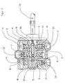
- the adjustment device has two as Gears trained actuators 2, 5, which in a Position freely rotatable around a cylindrical transmission element 3 are stored.
- the actuators or the gears 2, 5 are with racks 22, 23 in engagement, on which the Actuating cables 24, 25 are articulated.
- a gear 21 is rotatably arranged, which interacts with a rack 20.
- This rack 20 is in turn connected to the actuating cable 27, which, as already described above, on the control shaft 34 of the Hydraulic drive for adjusting the speed and for one Left and right rotation of the drum 33 acts.
- a clutch switching element 4 axially slidably guided, which causes that when engaged Coupling or positive connection between the one Actuator 2 and the transmission element 3, the further actuator 5 on the transmission link 3 freely rotatable without operative connection is and vice versa.
- coupling elements 9, 10 For the rotationally fixed connection of the respective actuator 2, 5 with the transmission element 3 are coupling elements 9, 10 provided, which in the embodiment chosen here are designed as balls. Of course it is possible to the coupling members other rolling element shapes give.
- the coupling members 9, 10 are in a transverse bore 11, 12 of the hollow cylindrical section 6 of the transmission member 3 added radially movable.
- the ball links 9, 10 For the generation of the positive connection snap the ball links 9, 10 in assigned recess 13, 14 on the bearing surfaces 7, 8 of the respective actuator 2, 5 and can be uncoupled Dodge position from these wells 13, 14.
- the Clutch switching element two reduced in diameter Contact surfaces 15, 16 on which the coupling members 9, 10th rest in the disengaged clutch position. There is one between these two contact surfaces 15, 16 adjacent to the outer surface of the hollow cylinder 6 cylindrical contact surface 17, by means of which the corresponding Coupling member 9 or 10 for producing the positive Connection in the associated recess 13 or 14 of the respective actuator 2, 5 is held.
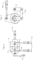
- FIG. 7 to 9 Another embodiment of an actuating device is shown in Figures 7 to 9 shown, with identical components with are provided with the same reference numerals.
- the difference in Embodiment according to Figures 7 to 9 compared to the above described is that instead of gear-rack pairs with the actuators 2, 5 now Swivel levers are provided, the actuating cables 24, 25 are articulated to angular joints 38 by means of rod joints 40.
- Another difference is that the Transmission link 3 directly via a lever joint 39 on the Control shaft 34 of the hydraulic drive 32 acts.
- the Actuator 1 or the transmission member 3 immediately on the control shaft 34 of the hydraulic drive 32 is flanged.
- the invention is also advantageous for the steering Motor yachts can be used, with the possibility of steering Head. and auxiliary control stands.
Landscapes
- Engineering & Computer Science (AREA)
- General Engineering & Computer Science (AREA)
- Mechanical Engineering (AREA)
- Physics & Mathematics (AREA)
- General Physics & Mathematics (AREA)
- Automation & Control Theory (AREA)
- Health & Medical Sciences (AREA)
- Public Health (AREA)
- Transportation (AREA)
- Mechanical Operated Clutches (AREA)
Abstract
Description
Die Erfindung bezieht sich auf eine Stellvorrichtung gemäß dem
Oberbegriff des Anspruches 1.The invention relates to an actuating device according to the
Preamble of
Eine Stellvorrichtung der eingangs genannten Art ist aus der
EP-B1 0 053 215 bekannt. Diese Stellvorrichtung weist
zusätzlich eine Rückstelleinrichtung auf, welche ein, bspw. auf
einen Hydraulikantrieb bei Baumaschinen, wie bspw. Rüttelwalzen
einwirkendes Übertragungsglied in eine vorgegebene Stellung
zurückzustellen trachtet, um eine mit Sicherheitsabschaltung
des Fahrantriebes bewirken.An actuator of the type mentioned is from the
EP-
Bei einem Betonmischfahrzeug wird zum Betätigen der für die Drehung der Betontrommel vorgesehenen Hydraulikpumpe eine mechanisch-flexible Fernbetätigung eingesetzt, welche über ein, bspw. am Fahrzeugheck angeordnetes Gebergeräte betätigt wird. Häufig sind derartige Gebergeräte auch in der Fahrzeugkabine angeordnet, um die Hydraulikpumpe, bspw. zum Entleeren der Betontrommel, auch vom Führerhaus bedienen zu können, sofern dies baustellenseitig möglich ist. In diesem Fall ist der von der Fahrzeugkabine ausgehende Betätigungszug und derjenige vom Fahrzeugheck kommende Betätigungszug synchron an die Hydraulikpumpe geschaltet. Dies hat zur Folge, daß bei Betätigung des einen Gebers der andere Geber zwangsweise mit betätigt wird, wodurch eine Schwergängigkeit bzw. einen Verlust an Wirkleistung gegeben ist.In the case of a concrete mixer truck, the for the Rotation of the concrete drum provided hydraulic pump mechanically flexible remote control used, which over a, For example, encoder devices arranged at the rear of the vehicle are actuated. Such encoder devices are often also in the vehicle cabin arranged to drain the hydraulic pump, for example Concrete drum, can also be operated from the cab, provided that this is possible on site. In this case it is from the actuating cable outgoing from the vehicle cabin and that from the The rear of the actuating cable coming synchronously to the Hydraulic pump switched. This has the consequence that at Actuation of one encoder the other encoder with is operated, causing a stiffness or a loss is given in active power.
Davon ausgehend liegt der Erfindung die Aufgabe zugrunde, eine Stellvorrichtung der eingangs genannten Art anzugeben, welche eine Betätigung von zwei verschiedenen Orten aus ohne großen Kraftaufwand erlaubt. Based on this, the invention is based on the object Actuating device of the type mentioned to specify which an operation from two different locations without large Force allowed.
Diese Aufgabe wird gelöst durch die Merkmale des Anspruches 1.This object is achieved by the features of
Durch die Erfindung ist eine leichtgängige Betätigung von Aggregaten, wie bspw. Hydraulikpumpen von zwei verschiedenen Orten aus ermöglicht, wobei bei einer Betätigung des einen Stellgliedes das jeweils andere entsprechend der Stellung des Kupplungsgliedes sich außer Wirkstellung mit dem auf das Aggregat einwirkende Übertragungsglied befindet. Die Kupplungseinrichtung ermöglicht ein wechselseitiges, zwangsgesteuertes bzw. zwangsläufiges Ein- und Auskuppeln von Stellgliedern und Übertragungsteil.The invention is a smooth operation of Units, such as hydraulic pumps from two different Locations made possible, with an actuation of one Actuator the other according to the position of the Coupling member out of active position with that on the Unit acting transmission link is located. The Coupling device enables reciprocal, positively controlled or automatically engaging and disengaging Actuators and transmission part.
Ausgestaltungen der Erfindung sind Gegenstand weiterer Ansprüche.Embodiments of the invention are the subject of further Expectations.
Weitere Ziele, Vorteile, Merkmale und Anwendungsmöglichkeiten der vorliegenden Erfindung ergeben sich aus der nachfolgenden Beschreibung der Ausführungsbeispiele anhand der Zeichnungen. Dabei bilden alle beschriebenen und/oder bildlich dargestellten Merkmale für sich oder in beliebiger sinnvoller Kombination den Gegenstand der vorliegenden Erfindung, auch unabhängig von ihrer Zusammenfassung in den Ansprüchen oder deren Rückbeziehung.Further goals, advantages, features and possible applications of the present invention result from the following Description of the exemplary embodiments with reference to the drawings. All described and / or illustrated form Features for themselves or in any meaningful combination Subject of the present invention, regardless of their summary in the claims or their Relationship.
Es zeigen:
Figur 1- ein Betonmischfahrzeug mit einer erfindungsgemäßen Stellvorrichtung,
Figur 2- eine Stellvorrichtung gemäß
Figur 1 in einer Schnittdarstellung, Figur 3- die Verstellvorrichtung gemäß
Figur 2 in einer Seitenansicht, Figur 4- die Stellvorrichtung gemäß
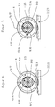
Figur 2 in einer Draufsicht, Figur 5- einen Schnitt durch die Stellvorrichtung gemäß
Figur 2 mit eingerückter Kupplung bzgl. des einen Stellgliedes, Figur 6- einen Schnitt durch die Stellvorrichtung gemäß
Figur 2, jedoch in ausgerückter Kuppelstellung des einen Stellgliedes, - Figur 7
- eine weitere Ausführungsform einer erfindungsgemäßen Stellvorrichtung, teilweise geschnitten,
- Figur 8
- die Stellvorrichtung gemäß Figur 7 in einer Draufsicht und
Figur 9- die Stellvorrichtung gemäß Figur 7 in einer Seitenansicht.
- Figure 1
- a concrete mixing vehicle with an adjusting device according to the invention,
- Figure 2
- 2 shows an adjusting device according to FIG. 1 in a sectional view,
- Figure 3
- 2 shows the adjustment device according to FIG. 2 in a side view,
- Figure 4
- 2 in a top view,
- Figure 5
- 3 shows a section through the adjusting device according to FIG. 2 with the clutch engaged with respect to the one actuator,
- Figure 6
- 3 shows a section through the adjusting device according to FIG. 2, but in the disengaged coupled position of the one actuator,
- Figure 7
- another embodiment of an adjusting device according to the invention, partially cut,
- Figure 8
- 7 in a top view and
- Figure 9
- the actuating device according to Figure 7 in a side view.
Das Betonmischfahrzeug gemäß Figur 1 weist einen
Hydraulikantrieb 32 zur Drehung der den Beton aufnehmenden
Trommel 33 auf. Der Hydraulikantrieb 32 wird über den (nicht
gesondert angezogenen) Motor des Fahrzeuges antrieben. Um den
Hydraulikantrieb 32 für eine Links- oder Rechtsdrehung der
Trommel 33 mit unterschiedlicher Drehzahl zum Mischen und
Entleeren des Betons aus der Trommel 33 anzusteuern, ist eine
Stelleinrichtung 1 vorgesehen, welche alternativ über ein in
der Fahrzeugkabine 31 angeordnetes Gebergerät 28 und ein am
Fahrzeugheck angeordnetes Gebergerät 30 vermittels von
Fernbetätigungen 24, 25 betätigbar ist. Die Stellvorrichtung 1
weist, wie noch weiter unten näher erläutert, eine Kupplung
auf, derart, daß sich bei Betätigung des einen Gebers 28 bzw.
30 der jeweils andere Geber 30 bzw. 28 nicht in Wirkstellung
befindet und damit nicht zwangsläufig mitbetätigt werden kann.
Das Umschalten der Kupplung von dem einen Geber 28 auf den
anderen Geber 30 erfolgt mittels eines weiteren Gebers 29,
welcher über einen Betätigungszug 26 an die Stellvorrichtung 1
anschließt. Hierdurch ist es auch möglich, bei einem Abstellen
des Fahrzeuges den Geber 30 am Fahrzeugheck durch Umschalten
auf den Geber 28 unwirksam zu schalten, so daß keine unbefugte
Betätigung des Hydraulikantriebes 32 von außen möglich ist.The concrete mixer vehicle according to FIG. 1 has one
Bei dem hier gewählten Ausführungsbeispiel erfolgt die
Verstellung des Hydraulikaggregates ebenfalls über einen
Betätigungszug 27, welcher an die Regelwelle 34 des Antriebes
32 anschließt. Selbstverständlich ist es auch möglich, daß die
Verstellvorrichtung 1 unmittelbar auf die mit Bezugszeichen 34
angezogene Regelwelle für die Verstellung der Drehzahl und
Rechts- oder Linkslauf der Trommel 33 des Hydraulikantriebes 32
einwirkt.In the embodiment chosen here, the
Adjustment of the hydraulic unit also via
Die Verstellvorrichtung gemäß Figuren 2 bis 6 weist zwei als
Zahnräder ausgebildete Stellglieder 2, 5 auf, welche in einer
Stellung frei drehbar um ein zylindrisches Übertragungsglied 3
gelagert sind. Die Stellglieder bzw. die Zahnräder 2, 5 stehen
mit Zahnstangen 22, 23 in Eingriff, an welchen die
Betätigungszüge 24, 25 angelenkt sind. Auf dem einen Ende des
Übertragungsgliedes 3 ist ein Zahnrad 21 drehfest angeordnet,
welches mit einer Zahnstange 20 zusammenwirkt. Diese Zahnstange
20 ist wiederum mit dem Betätigungszug 27 verbunden, welcher,
wie oben bereits beschrieben, auf die Regelwelle 34 des
Hydraulikantriebes zur Verstellung der Drehzahl und für eine
Links- und Rechtsdrehung der Trommel 33 einwirkt.The adjustment device according to Figures 2 to 6 has two as
Gears trained
Innerhalb eines hohlzylindrischen Abschnittes 6 des
Übertragungsgliedes 3 ist ein Kupplungsschaltglied 4 axial
verschieblich geführt, welches bewirkt, daß bei eingerückter
Kupplung bzw. formschlüssiger Verbindung zwischen dem einen
Stellglied 2 und dem Übertragungsglied 3 das weitere Stellglied
5 auf dem Übertragungsglied 3 ohne Wirkverbindung frei drehbar
ist und umgekehrt.Within a hollow
Für die drehfeste Verbindung des jeweiligen Stellgliedes 2, 5
mit dem Übertragungsglied 3 sind Kupplungsglieder 9, 10
vorgesehen, welche bei dem hier gewählten Ausführungsbeispiel
als Kugeln ausgebildet sind. Selbstverständlich ist es auch
möglich, den Kupplungsgliedern andere Wälzkörperformen zu
geben. Die Kupplungsglieder 9, 10 sind in einer Querbohrung 11,
12 des hohlzylindrischen Abschnittes 6 des Übertragungsgliedes
3 radial beweglich aufgenommen. Für die Erzeugung der
formschlüssigen Verbindung rasten die Kugelglieder 9, 10 in
zugeordnete Vertiefung 13, 14 an den Lagerflächen 7, 8 des
jeweiligen Stellgliedes 2, 5 ein und können in der entkuppelten
Stellung aus diesen Vertiefungen 13, 14 ausweichen.For the rotationally fixed connection of the
Zur Ausführung dieser Schaltbewegungen weist das
Kupplungsschaltglied zwei im Durchmesser reduzierte
Anlageflächen 15, 16 auf, an welchen die Kupplungsglieder 9, 10
in der jeweils ausgerückten Kupplungsstellung aufliegen.
Zwischen diesen beiden Anlageflächen 15, 16 befindet sich eine
an die Mantelfläche des Hohlzylinders 6 angrenzende
zylindrische Anlagefläche 17, mittels welcher das entsprechende
Kupplungsglied 9 bzw. 10 zur Herstellung der formschlüssigen
Verbindung in der zugeordneten Vertiefung 13 bzw. 14 des
jeweiligen Stellgliedes 2, 5 gehalten ist. Wird nun das
Kupplungsschaltglied 4 von der in Figur 2 dargestellten
Schaltstellung bzgl. des hohlzylindrischen Abschnittes 6 in
axialer Richtung nach rechts geschoben wird, gleiten die
Kupplungsglieder 10 bzw. die Kugeln entlang der konischen
Anlaufschräge 19 und wandern radial nach außen, bis sie von der
zylindrischen Anlagefläche 17 des Kupplungsschaltgliedes 4 in
die Vertiefungen 14 an der Lagerfläche 8 des Verstellgliedes 5
einrastet und in dieser Stellung gehalten sind. Gleichzeitig
mit dieser axialen Verschiebung des Schaltgliedes 4 wandern die
Kupplungsglieder 9 aus den Vertiefungen 13 an der Lagerfläche 7
des Stellgliedes 2 längs der konischen Anlaufschräge 18 nach
radial innen, bis die Kupplungsglieder 9 in der Querbohrung 11
des Stellgliedes 2 aufgenommen sind und damit die drehfeste
Verbindung aufgehoben ist. Dieser Sachverhalt des Kuppelns und
Entkuppelns ist beispielhaft in Figuren 5 und 6 dargestellt.For the execution of these switching movements, the
Clutch switching element two reduced in diameter
Contact surfaces 15, 16 on which the
Für die axiale Bewegung des Kupplungschaltgliedes 4 bzgl. des
hohlzylindrischen Abschnittes 6 des Übertragungsgliedes 3 ist
ebenfalls eine mechanisch-flexible Fernbetätigung 26
vorgesehen, welche über einen Anschlußbolzen 35 in einer
Bohrung 37 des Kupplungsschaltgliedes 4 gehalten, bspw.
eingeschraubt ist.For the axial movement of the
Eine weitere Ausführungsform einer Stellvorrichtung ist in
Figuren 7 bis 9 dargestellt, wobei identische Bauteile mit
gleichen Bezugszeichen versehen sind. Der Unterschied der
Ausführungsform gemäß Figuren 7 bis 9 gegenüber der oben
beschriebenen besteht einmal darin, daß anstelle von Zahnrad-Zahnstangen-Paaren
bei den Stellglieder 2, 5 nunmehr
Schwenkhebel vorgesehen sind, wobei die Betätigungszüge 24, 25
mittels Stangengelenken 40 an Winkelgelenken 38 angelenkt sind.
Ein weiterer Unterschied besteht darin, daß das
Übertragungsglied 3 direkt über ein Hebelgelenk 39 auf die
Regelwelle 34 des Hydraulikantriebes 32 einwirkt.
Selbstverständlich ist es auch möglich, daß die
Stellvorrichtung 1 bzw. das Übertragungsglied 3 unmittelbar an
die Regelwelle 34 des Hydraulikantriebes 32 angeflanscht ist.Another embodiment of an actuating device is shown in
Figures 7 to 9 shown, with identical components with
are provided with the same reference numerals. The difference in
Embodiment according to Figures 7 to 9 compared to the above
described is that instead of gear-rack pairs
with the
Die Erfindung ist mit Vorteil auch für die Lenkung bei Motorjachten einsetzbar, mit der Möglichkeit der Lenkung von Haupt. und Nebenfahrständen. The invention is also advantageous for the steering Motor yachts can be used, with the possibility of steering Head. and auxiliary control stands.
- 11
- - Stellvorrichtung- adjusting device
- 22nd
- - Stellglied, Zahnrad- actuator, gear
- 33rd
- - Übertragungsglied- Transmission link
- 44th
- - Kupplungsschaltglied- clutch switching element
- 55
- - Stellglied, Zahnrad- actuator, gear
- 66
- - Abschnitt- Section
- 77
- - Lagerfläche- Storage area
- 88th
- - Lagerfläche- Storage area
- 99
- - Kupplungsglied- coupling link
- 1010th
- - Kupplungsglied- coupling link
- 1111
- - Querbohrung- cross hole
- 1212th
- - Querbohrung- cross hole
- 1313
- - Vertiefung- Deepening
- 1414
- - Vertiefung- Deepening
- 1515
- - Anlagefläche- contact surface
- 1616
- - Anlagefläche- contact surface
- 1717th
- - Anlagefläche- contact surface
- 1818th
- - Anlaufschräge- ramp
- 1919th
- - Anlaufschräge- ramp
- 2020th
- - Zahnstange- rack
- 2121
- - Zahnrad- gear
- 2222
- - Zahnstange- rack
- 2323
- - Zahnstange- rack
- 2424th
- - Fernbetätigung- remote control
- 2525th
- - Fernbetätigung- remote control
- 2626
- - Fernbetätigung- remote control
- 2727
- - Fernbetätigung- remote control
- 2828
- - Geber- Giver
- 2929
- - Geber- Giver
- 3030th
- - Geber- Giver
- 3131
- - Fahrzeugkabine- vehicle cabin
- 3232
- - Hydraulikpumpe- Hydraulic pump
- 3333
- - Trommel - drum
- 3434
- - Regelwelle- control shaft
- 3535
- - Anschlußbolzen- connecting bolts
- 3737
- - Bohrung- Drilling
- 3838
- - Winkelgelenk- angle joint
- 3939
- - Hebelgelenk- Lever joint
- 4040
- - Stangengelenk- rod joint
Claims (11)
Applications Claiming Priority (2)
| Application Number | Priority Date | Filing Date | Title |
|---|---|---|---|
| DE19629443 | 1996-07-22 | ||
| DE19629443 | 1996-07-22 |
Publications (1)
| Publication Number | Publication Date |
|---|---|
| EP0821174A1 true EP0821174A1 (en) | 1998-01-28 |
Family
ID=7800444
Family Applications (1)
| Application Number | Title | Priority Date | Filing Date |
|---|---|---|---|
| EP97112531A Withdrawn EP0821174A1 (en) | 1996-07-22 | 1997-07-22 | Actuating device |
Country Status (1)
| Country | Link |
|---|---|
| EP (1) | EP0821174A1 (en) |
Cited By (2)
| Publication number | Priority date | Publication date | Assignee | Title |
|---|---|---|---|---|
| WO2014166632A1 (en) * | 2013-04-12 | 2014-10-16 | Stetter Gmbh | Truck mixer for concrete, mortar or similar, flowing materials |
| WO2015128150A1 (en) * | 2014-02-25 | 2015-09-03 | Putzmeister Engineering Gmbh | Concrete mixer with adjusting and reversing unit |
Citations (13)
| Publication number | Priority date | Publication date | Assignee | Title |
|---|---|---|---|---|
| FR357924A (en) * | 1905-09-21 | 1906-01-20 | Josef Schaschl | Device for alternately or simultaneously stalling or disengaging toothed wheels mounted on two or more shafts, for changing the transmission ratio, especially applicable to automobiles |
| US1647932A (en) * | 1925-11-30 | 1927-11-01 | Pozder Steve | Transmission-gearing-clutching means |
| GB654813A (en) * | 1947-11-27 | 1951-06-27 | Siam | Improvements in or relating to hydraulic remote control systems |
| GB894379A (en) * | 1961-02-09 | 1962-04-18 | John Franklin Morse | Interlocking mechanism for single lever and auxiliary lever boat engine control |
| FR2136663A5 (en) * | 1972-04-18 | 1972-12-22 | Saint Martin Pierre | |
| DE2351228A1 (en) * | 1973-10-12 | 1975-04-17 | Daimler Benz Ag | Coupling between synchro shaft and gear - comprising pairs of opposed one-way detents releasable by common operating member |
| US4271942A (en) * | 1978-10-02 | 1981-06-09 | Allis-Chalmers Corporation | Two-speed power take-off |
| DE3241608A1 (en) * | 1981-12-01 | 1983-06-16 | Steyr-Daimler-Puch AG, 1010 Wien | Brake-actuating device for vehicles which can be used in two opposite directions of travel |
| EP0053215B1 (en) | 1980-11-29 | 1984-06-06 | Losenhausen Maschinenbau AG& Co Kommanditgesellschaft | Adjusting device |
| EP0462904A2 (en) * | 1990-06-21 | 1991-12-27 | Technology Finance Corporation (Proprietary) Limited | Gearbox |
| DE4127538A1 (en) * | 1990-08-21 | 1992-02-27 | Caterpillar Mitsubishi Ltd | ENGINE CONTROL DEVICE |
| US5216934A (en) * | 1988-09-22 | 1993-06-08 | Sanshin Kogyo Kabushiki Kaisha | Remote control mechanism |
| DE4437184A1 (en) * | 1994-10-18 | 1996-04-25 | Roemheld A Gmbh & Co Kg | Patient bed head and foot part adjuster drive |
-
1997
- 1997-07-22 EP EP97112531A patent/EP0821174A1/en not_active Withdrawn
Patent Citations (13)
| Publication number | Priority date | Publication date | Assignee | Title |
|---|---|---|---|---|
| FR357924A (en) * | 1905-09-21 | 1906-01-20 | Josef Schaschl | Device for alternately or simultaneously stalling or disengaging toothed wheels mounted on two or more shafts, for changing the transmission ratio, especially applicable to automobiles |
| US1647932A (en) * | 1925-11-30 | 1927-11-01 | Pozder Steve | Transmission-gearing-clutching means |
| GB654813A (en) * | 1947-11-27 | 1951-06-27 | Siam | Improvements in or relating to hydraulic remote control systems |
| GB894379A (en) * | 1961-02-09 | 1962-04-18 | John Franklin Morse | Interlocking mechanism for single lever and auxiliary lever boat engine control |
| FR2136663A5 (en) * | 1972-04-18 | 1972-12-22 | Saint Martin Pierre | |
| DE2351228A1 (en) * | 1973-10-12 | 1975-04-17 | Daimler Benz Ag | Coupling between synchro shaft and gear - comprising pairs of opposed one-way detents releasable by common operating member |
| US4271942A (en) * | 1978-10-02 | 1981-06-09 | Allis-Chalmers Corporation | Two-speed power take-off |
| EP0053215B1 (en) | 1980-11-29 | 1984-06-06 | Losenhausen Maschinenbau AG& Co Kommanditgesellschaft | Adjusting device |
| DE3241608A1 (en) * | 1981-12-01 | 1983-06-16 | Steyr-Daimler-Puch AG, 1010 Wien | Brake-actuating device for vehicles which can be used in two opposite directions of travel |
| US5216934A (en) * | 1988-09-22 | 1993-06-08 | Sanshin Kogyo Kabushiki Kaisha | Remote control mechanism |
| EP0462904A2 (en) * | 1990-06-21 | 1991-12-27 | Technology Finance Corporation (Proprietary) Limited | Gearbox |
| DE4127538A1 (en) * | 1990-08-21 | 1992-02-27 | Caterpillar Mitsubishi Ltd | ENGINE CONTROL DEVICE |
| DE4437184A1 (en) * | 1994-10-18 | 1996-04-25 | Roemheld A Gmbh & Co Kg | Patient bed head and foot part adjuster drive |
Cited By (2)
| Publication number | Priority date | Publication date | Assignee | Title |
|---|---|---|---|---|
| WO2014166632A1 (en) * | 2013-04-12 | 2014-10-16 | Stetter Gmbh | Truck mixer for concrete, mortar or similar, flowing materials |
| WO2015128150A1 (en) * | 2014-02-25 | 2015-09-03 | Putzmeister Engineering Gmbh | Concrete mixer with adjusting and reversing unit |
Similar Documents
| Publication | Publication Date | Title |
|---|---|---|
| EP1799396B1 (en) | Replacement device for clamping heads comprising a plurality of clamping jaws | |
| EP2903882B1 (en) | Heavy road vehicle with normal steering and crab steering | |
| DE202005002585U1 (en) | Linear motor drive, has brake system with bushing, which is firmly attached to projections on guide flange that is fixed to spindle nut when switch cam actuates limit switch in flange pipe to switch off DC motor | |
| DE102018132356A1 (en) | Wheel spoiler with spatially compact overload clutch | |
| DE10027083B4 (en) | Transport device for a conveyor crane | |
| DE60028734T2 (en) | ELECTRICAL OPERATION FOR GEARBOX | |
| WO2000030885A2 (en) | Selector device for the gearbox of a motor vehicle | |
| DE3824296A1 (en) | DEVICE FOR SWITCHING A MOTOR VEHICLE TRANSMISSION | |
| DE2823460A1 (en) | PEDAL ARRANGEMENT FOR CONTROLLING ENGINE AND TRANSMISSION IN MOTOR VEHICLES | |
| DE3536121C2 (en) | Gear shifting device | |
| DE19901451A1 (en) | Shaft steered floor transport unit for use in e.g. stores comprises electric signal generator which senses angular displacement and/or position of steering shaft, and controls wheel steering motor | |
| DE19544837A1 (en) | Gear shift for manual operation of multiple gear, with gear shift lever | |
| DE2216858A1 (en) | Marine propulsion with reverse gear | |
| EP0480159A1 (en) | Device for the introduction of a steering compensation | |
| EP0562598A1 (en) | Articulated joint between two articulated vehicles | |
| EP0821174A1 (en) | Actuating device | |
| DE3405038A1 (en) | SWITCHING CLUTCH | |
| WO2008107284A1 (en) | Auxiliary mass for a selector shaft in a gearbox | |
| DE2331647C2 (en) | Switching device for a change gear in vehicles | |
| DE112007002890T5 (en) | Steering device with a ball screw | |
| DE2055364A1 (en) | Gearboxes for steering vehicle wheels, in particular motor vehicles with multi-axle steering | |
| EP1291560A2 (en) | Power assisted gear shift device | |
| DE20310055U1 (en) | Manual shift lever for a vehicle transmission | |
| DE3612619C2 (en) | ||
| WO2014053477A1 (en) | Heavy road vehicle with normal steering and crab steering |
Legal Events
| Date | Code | Title | Description |
|---|---|---|---|
| PUAI | Public reference made under article 153(3) epc to a published international application that has entered the european phase |
Free format text: ORIGINAL CODE: 0009012 |
|
| AK | Designated contracting states |
Kind code of ref document: A1 Designated state(s): DE ES FR GB IT NL |
|
| RBV | Designated contracting states (corrected) |
Designated state(s): DE ES FR GB IT NL |
|
| RBV | Designated contracting states (corrected) |
Designated state(s): DE ES FR GB IT NL |
|
| STAA | Information on the status of an ep patent application or granted ep patent |
Free format text: STATUS: THE APPLICATION IS DEEMED TO BE WITHDRAWN |
|
| 18D | Application deemed to be withdrawn |
Effective date: 19980729 |