EP0820420B1 - Auxiliary lifting forks for extended-length pallet trucks - Google Patents
Auxiliary lifting forks for extended-length pallet trucks Download PDFInfo
- Publication number
- EP0820420B1 EP0820420B1 EP96908697A EP96908697A EP0820420B1 EP 0820420 B1 EP0820420 B1 EP 0820420B1 EP 96908697 A EP96908697 A EP 96908697A EP 96908697 A EP96908697 A EP 96908697A EP 0820420 B1 EP0820420 B1 EP 0820420B1
- Authority
- EP
- European Patent Office
- Prior art keywords
- forks
- primary
- pallet truck
- fork
- lifting mechanism
- Prior art date
- Legal status (The legal status is an assumption and is not a legal conclusion. Google has not performed a legal analysis and makes no representation as to the accuracy of the status listed.)
- Expired - Lifetime
Links
Images




Classifications
-
- B—PERFORMING OPERATIONS; TRANSPORTING
- B62—LAND VEHICLES FOR TRAVELLING OTHERWISE THAN ON RAILS
- B62B—HAND-PROPELLED VEHICLES, e.g. HAND CARTS OR PERAMBULATORS; SLEDGES
- B62B3/00—Hand carts having more than one axis carrying transport wheels; Steering devices therefor; Equipment therefor
- B62B3/04—Hand carts having more than one axis carrying transport wheels; Steering devices therefor; Equipment therefor involving means for grappling or securing in place objects to be carried; Loading or unloading equipment
- B62B3/06—Hand carts having more than one axis carrying transport wheels; Steering devices therefor; Equipment therefor involving means for grappling or securing in place objects to be carried; Loading or unloading equipment for simply clearing the load from the ground
- B62B3/0618—Hand carts having more than one axis carrying transport wheels; Steering devices therefor; Equipment therefor involving means for grappling or securing in place objects to be carried; Loading or unloading equipment for simply clearing the load from the ground using fluid lifting mechanisms
-
- B—PERFORMING OPERATIONS; TRANSPORTING
- B62—LAND VEHICLES FOR TRAVELLING OTHERWISE THAN ON RAILS
- B62B—HAND-PROPELLED VEHICLES, e.g. HAND CARTS OR PERAMBULATORS; SLEDGES
- B62B3/00—Hand carts having more than one axis carrying transport wheels; Steering devices therefor; Equipment therefor
- B62B3/04—Hand carts having more than one axis carrying transport wheels; Steering devices therefor; Equipment therefor involving means for grappling or securing in place objects to be carried; Loading or unloading equipment
- B62B3/06—Hand carts having more than one axis carrying transport wheels; Steering devices therefor; Equipment therefor involving means for grappling or securing in place objects to be carried; Loading or unloading equipment for simply clearing the load from the ground
-
- B—PERFORMING OPERATIONS; TRANSPORTING
- B62—LAND VEHICLES FOR TRAVELLING OTHERWISE THAN ON RAILS
- B62B—HAND-PROPELLED VEHICLES, e.g. HAND CARTS OR PERAMBULATORS; SLEDGES
- B62B2203/00—Grasping, holding, supporting the objects
- B62B2203/20—Grasping, holding, supporting the objects using forks or tines
- B62B2203/26—Grasping, holding, supporting the objects using forks or tines the fork being independent from the supporting arms in which the wheels are incorporated
Definitions
- This invention relates to an improved pallet truck having an extended length pair of forks capable of supporting multiple, side-by-side, pallets which may be raised well above the floor to assist an operator in an order selection operation.
- a typical order selection or stock picking operation using a pallet truck an operator often starts with an empty pallet carried on the forks of a pallet truck onto which a load is accumulated, one item or carton at a time as he or she moves through the aisles of the warehouse until a completed order has been assembled.
- the operator moves the truck either by riding or walking to the desired location, picks the desired item from a rack and places it on the pallet.
- a truck with extended length forks that can carry two or more pallets side by side on its forks improves efficiency and logistics; however, such trucks generally have forks that can raise only approximately 15 to 23 cms (6 to 9 ins) above the floor.
- One such pallet truck is a Series PE Rider Pallet Truck manufactured by Crown Equipment Corporation, the assignee of the present invention.
- the height of the forks may be adjusted from a lowermost position, where the bottoms of the pallets are in contact with the floor and the forks are clear of the underneath surface of the pallets, to a raised position, where the pallets have been lifted clear of contact with the floor and are free to move about a warehouse.
- Order selecting trucks provided with a high lift mechanism, ones that raise the pallet 46 cms (18 ins) or more above the floor, can assist the operator in loading a pallet quickly and conveniently.
- Existing trucks of this type only provide a fork length sufficient to handle a single pallet. It would be desirable in some circumstances to provide an order picking truck where multiple pallets. at least two, can be placed in excess of 30 cms (12 ins), and preferably in excess of 46 cms (18 ins), above the floor, while the load on the pallets is fully supported until the order selecting operation is complete and the pallets lowered to the floor.
- US-A-3265158 discloses a pallet truck having a pair of pallet legs and a pair of fork arms above the legs. Lifting mechanisms are provided to lift both the fork arms and the legs, and the fork arms nest over the legs when in their lower positions.
- a first aspect of the invention consists in a pallet truck comprising a truck body, a first fork lifting mechanism carried by said truck body, a pair of primary forks having a first end attached to said first fork lifting mechanism, load wheels positioned to support a second end of said primary forks, a pair of secondary forks mounted above said primary forks, said secondary forks having a first end and a second end, being mounted directly above said primary forks and being configured to nest with said primary forks when in their lower position, and a second fork lifting mechanism for raising said first end of said secondary forks from a lower position to a raised.
- said pallet truck being characterized in that it further comprises a load wheel lifting mechanism responsive to the first fork lifting mechanism for causing said second end of said primary forks to be raised from a lower level to an upper level simultaneously with the raising of said first end thereby to maintain said primary forks level, a support mechanism attached to said secondary forks at a location remote from said first end for supporting said second end of said secondary forks while in a raised position, said support mechanism including a support hydraulic cylinder placed between each secondary fork and its corresponding primary fork, and a hydraulic circuit for supplying hydraulic pressure to said support hydraulic cylinders.
- a second aspect of the invention consists in a method of order selecting using a pallet truck, as defined by the first aspect, provided with said secondary forks of extended length capable of supporting multiple side-by-side pallets, the method including the steps of placing one or more pallets on the secondary forks; raising said first end of the secondary forks above the floor, lowering the secondary forks to place the pallets in contact with the floor; and backing the pallet truck from under the loaded pallets; characterised in that said first end is raised in excess of 30 cms (12 ins) above the floor and said support mechanism is provided to the secondary forks at said location remote from said first end while in the raised position to provide a stable platform while items are accumulated on the pallets.
- the present invention thus includes a pallet truck provided with a pair of forks capable of having a length from one end to another sufficient to hold multiple industry standard pallets in a side-by-side relationship.
- the fork lifting mechanism positions the forks from a lower position, where the pallets carried thereby are in contact with the floor, to an upper position, in excess of 30 cms (12 ins) above the floor.
- the fork support mechanism supports the other end of the forks as the forks are raised and lowered by the fork lifting mechanism.
- the first set of forks is conventional, that is, they are similar to those used in a conventional pallet truck, being capable of raising a pallet from the floor to a position clear of the floor with the outer ends of these forks supported by load wheels attached to levers which maintain the forks parallel with the floor.
- a pair of upper or secondary forks is placed over, in nesting relation to, the first set of forks.
- the fork lifting mechanism includes the first fork lifting mechanism, which is supported on the body of the pallet truck for raising the lower forks, and the second fork lifting mechanism, which is supported on and carried by the first or primary forks for raising the secondary forks from their nested position to a convenient height for the operator.
- a support mechanism for the upper forks is attached between those forks and the ends of the lower to support the upper forks while they are in a raised position.
- the truck When the upper forks are lowered into nesting relation with the lower forks, the truck functions similarly to a conventional pallet truck in terms of loading and unloading pallets.
- the extended length secondary forks When the extended length secondary forks are raised, their ends are supported by hydraulic cylinders which provide rigidity and support, thus minimizing bending and movement of the fork ends.
- a hydraulic system insures that the pallets remains level, even during unequal loading since the stabilizing cylinders are isolated after lift.
- an operator activates a Raise button on the truck which activates a solenoid to power a motor-hydraulic pump package.
- the pump and associated manifold supplies high pressure hydraulic fluid or oil to the rest of the system.
- An adjustable relief valve controls overpressure and limits the maximum load lifting capability.
- a check valve prevents reverse hydraulic fluid flow.
- the lifting of the lower forks is done by the first fork lifting mechanism, a conventional low lift pallet truck mechanism using a hydraulic cylinder and four bar linkage to raise the pair of primary or lower forks and to adjust the load wheel support arms. In this lifting range, the maximum capacity load of the pallet truck can be lifted.
- an electrical switch is activated by the first or lower fork lift mechanism and hydraulic valves are actuated to isolate the lower fork lift cylinder from the hydraulic circuit.
- the hydraulic fluid is then diverted through an adjustable pressure reducing valve which limits the load which can be lifted above the lower forks.
- the hydraulic fluid is supplied simultaneously to a hydraulic cylinder in the second fork lifting mechanism and a flow divider block which supplies equal volume to each fork tip support or stabilizing cylinder.
- the operator activates a Lower button on the truck which in turn activates the lowering solenoid and hydraulic valves to allow hydraulic fluid to return to the reservoir from the mast and tip cylinders.
- One benefit of this invention is that it allows the operator to position the pallet higher from the floor.
- the operator may raise the forks to their maximum height with the pallet at least 30, and preferably 46 to 61 cms (12, and preferably 18 to 24 ins) off the floor, and as stock is added to the pallets, the forks may be lowered to maintain a desired stacking height while all forks are rigidly supported.
- the second fork lifting mechanism engages an electrical switch to deactivate hydraulic valves and allow hydraulic fluid from the first fork hydraulic cylinder to return to the reservoir and complete the lowering cycle.
- an extended length rider pallet truck 10 includes a power unit 15, which includes a motor (not shown) providing power to a drive wheel 20, a platform 25 on which an operator may ride, a control handle 30 for controlling the direction and speed of the truck, an operator grab bar 35 with function controls 40.
- a pair of castors 45 are placed outside the drive wheel.
- the truck is normally driven power unit first, or to the left as shown in Fig. 2, although the truck may also be moved in the reverse direction when desired.
- a bumper or debris guard 50 is placed under the truck to protect the drive wheel 20 and castors 45 from damage.
- a pair of primary or lower forks 60 are supported on a first fork lifting mechanism 70 which can raise the lower forks 60 from their lowermost position to an upper level approximately 23 cms (9 ins) above the floor.
- the first fork lifting mechanism is a basic four-bar arrangement with a primary hydraulic cylinder 75 (Fig. 5) providing the lifting force.
- a typical pallet truck of this type can lift 2722 to 3629 kgs (6000 to 8000 1bs).
- a load wheel 80 is placed at the outer end of each lower fork 60.
- the load wheel lifting mechanism 85 includes arms 87 connected to linkage rods 90 which cause the wheels to lower and support the lower forks as they are lifted.
- a battery 100 is carried at the heel end 62 of the lower forks and will be raised and lowered with the forks 60.
- a pair of secondary or upper forks 110 are positioned above the lower forks 60 and are carried by a second fork lifting mechanism 120 mounted on the lower forks 60.
- the second lifting mechanism includes a mast structure 125 formed from stationary channel members 130 and vertically movable channel members 135 which are guided by rollers (not shown).
- a secondary hydraulic lift cylinder 140 (shown in Figs 1 and 8) provides lifting power sufficient to raise the upper forks 110 up to approximately 61 cms (24 ins) above the floor 150.
- a vertical wall 155 is placed between the heel end 160 of the upper forks 110 and the lifting mechanism.
- Ends 170 of the upper forks 110 are stabilized by a second fork supporting mechanism 180, including hydraulic cylinders, that are connected between the ends of the upper forks and the ends 185 of the lower forks 60.
- a second fork supporting mechanism 180 including hydraulic cylinders, that are connected between the ends of the upper forks and the ends 185 of the lower forks 60.
- the stabilizing hydraulic cylinders 180 do not necessarily have to be connected to the ends of the upper forks, but it is preferred that they be connected to the ends of the lower forks since this provides a convenient mounting point.
- the upper forks 60 are shown as being double length, that is, they can support a pair of typical industry standard 102 to 123 cm (40 by 48 inch) pallets, but it is to be understood that the forks may be made longer, if desired. In some applications, the pallet length need only be as long as the narrow side of one pallet plus 75% of a second pallet. Thus, it is only required that the forks be of sufficient length to support at least two pallets. While only a single pallet 200 is shown on the upper forks 110 in Fig. 1, it is to be understood that multiple, side-by-side pallets many be carried on the forks. As shown, the pallet 200 is a block style pallet that includes a plurality of blocks or legs 202 that descend from an upper platform 204. The spacing between blocks 202 is standard and permits the forks of a pallet truck to pass freely therebetween.
- the upper fork 110 is a C-shaped member provided with a reinforcing strip 112.
- a hydraulic line 210 from the power unit 15 to the stabilizing cylinders 180 may be carried in the space formed between the strip 112 and the fork 110.
- the lower fork 60 is also provided with a reinforcing strip 62.
- the inside dimension D1 of the upper fork is greater than the outside dimension D2 of the lower fork 60, thus allowing the two fork sections to nest.
- the forks 60 and 110 are initially in a lowered position, as shown in Fig. 6. In this position, the forks may be placed under a pallet or a pallet previously on the forks may be deposited. The height of the upper surface of the upper forks is below the lower surface of a pallet in this configuration.
- the forks are raised to a first position.
- the load wheel 80 is lowered by action of the linkage rod 90, which is connected to the first lifting mechanism 70 (Fig. 5).
- the upper surface of forks 110 is about 23 cms (9 ins) above the floor, and thus the bottom of pallets carried on the forks will be clear of the floor, thus enabling the pallets to be moved.
- the load wheels are extended and support the outer ends of the forks, as is conventional with a PE Series Rider Pallet Truck.
- the upper forks 110 When the upper forks 110 are raised to their maximum height, as shown in Fig. 1, the upper surface of the forks will be approximately 61 cms (24 ins) or more above the floor. In this position, the operator may conveniently load the pallet from stock from racks adjacent the truck.
- the upper fork may be placed at any convenient height, from 23 to 61 cms (9 to 24 ins), depending on the desire of the operator.
- FIG. 8 A hydraulic schematic drawing of the improved pallet truck is shown in Fig. 8. This schematic is similar to the hydraulic schematic used in a conventional PE Series Pallet Truck but includes two additional features, namely a secondary lift cylinder 140 and the two stabilizing or fork tip cylinders 180. Hydraulic fluid is provided to the system from power unit 215, which includes a pump-motor unit, to a manifold 220. The secondary lift cylinder 140 will only be provided with hydraulic fluid after the primary lift cylinder 75 has reached its height limit, as indicated by the dotted lines showing the upward movement of the primary lift cylinder engaging the limit switch LMS1.
- Hydraulic device 225 including flow divider valve FDV and valves SV4 and SV5, insures that both stabilizing cylinders 180 receive the same hydraulic flow.
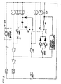
- the electrical schematic diagram of the truck is shown in Fig. 9. Power to the circuit is provided by the battery 100 through fuses F1 and F2.
- battery power is made available to the fork raise switch RAS, the fork lower switch LOS and the brake switch BRS.
- Forward travel is controlled by forward travel switch FS and reverse travel is controlled by reverse travel switch RS.
- Switches RAS and LOS are available on the control handle 30 and controls 40 on operator grab bar 35
- the brake switch BRS is controlled by the vertical position of the control handle 30, and the forward and reverse switches are controlled by twist grips on the control handle.
- This electrical configuration is conventional on a Series PE Rider Pallet Truck.
- limit switch LMS1 is fully closed when the lower or primary forks 60 are in their fully raised position
- limit switch LMS2 is shown with the upper or secondary forks 110 in their home, or lowered or nested, position.
Landscapes
- Engineering & Computer Science (AREA)
- Chemical & Material Sciences (AREA)
- Combustion & Propulsion (AREA)
- Transportation (AREA)
- Mechanical Engineering (AREA)
- Forklifts And Lifting Vehicles (AREA)
Abstract
Description
- This invention relates to an improved pallet truck having an extended length pair of forks capable of supporting multiple, side-by-side, pallets which may be raised well above the floor to assist an operator in an order selection operation.
- In a typical order selection or stock picking operation using a pallet truck, an operator often starts with an empty pallet carried on the forks of a pallet truck onto which a load is accumulated, one item or carton at a time as he or she moves through the aisles of the warehouse until a completed order has been assembled. The operator moves the truck either by riding or walking to the desired location, picks the desired item from a rack and places it on the pallet. A truck with extended length forks that can carry two or more pallets side by side on its forks improves efficiency and logistics; however, such trucks generally have forks that can raise only approximately 15 to 23 cms (6 to 9 ins) above the floor. One such pallet truck is a Series PE Rider Pallet Truck manufactured by Crown Equipment Corporation, the assignee of the present invention. The height of the forks may be adjusted from a lowermost position, where the bottoms of the pallets are in contact with the floor and the forks are clear of the underneath surface of the pallets, to a raised position, where the pallets have been lifted clear of contact with the floor and are free to move about a warehouse.
- Order selecting trucks provided with a high lift mechanism, ones that raise the pallet 46 cms (18 ins) or more above the floor, can assist the operator in loading a pallet quickly and conveniently. Existing trucks of this type, however, only provide a fork length sufficient to handle a single pallet. It would be desirable in some circumstances to provide an order picking truck where multiple pallets. at least two, can be placed in excess of 30 cms (12 ins), and preferably in excess of 46 cms (18 ins), above the floor, while the load on the pallets is fully supported until the order selecting operation is complete and the pallets lowered to the floor.
- US-A-3265158 discloses a pallet truck having a pair of pallet legs and a pair of fork arms above the legs. Lifting mechanisms are provided to lift both the fork arms and the legs, and the fork arms nest over the legs when in their lower positions.
- It is an object of the present invention to provide an improved pallet truck having a pair of forks capable of being of extended length for supporting multiple side-by-side pallets well above the floor to assist an operator in an order selection operation.
- Accordingly, a first aspect of the invention consists in a pallet truck comprising a truck body, a first fork lifting mechanism carried by said truck body, a pair of primary forks having a first end attached to said first fork lifting mechanism, load wheels positioned to support a second end of said primary forks, a pair of secondary forks mounted above said primary forks, said secondary forks having a first end and a second end, being mounted directly above said primary forks and being configured to nest with said primary forks when in their lower position, and a second fork lifting mechanism for raising said first end of said secondary forks from a lower position to a raised. position, said pallet truck being characterized in that it further comprises
a load wheel lifting mechanism responsive to the first fork lifting mechanism for causing said second end of said primary forks to be raised from a lower level to an upper level simultaneously with the raising of said first end thereby to maintain said primary forks level,
a support mechanism attached to said secondary forks at a location remote from said first end for supporting said second end of said secondary forks while in a raised position, said support mechanism including a support hydraulic cylinder placed between each secondary fork and its corresponding primary fork, and
a hydraulic circuit for supplying hydraulic pressure to said support hydraulic cylinders. - A second aspect of the invention consists in a method of order selecting using a pallet truck, as defined by the first aspect, provided with said secondary forks of extended length capable of supporting multiple side-by-side pallets, the method including the steps of
placing one or more pallets on the secondary forks;
raising said first end of the secondary forks above the floor,
lowering the secondary forks to place the pallets in contact with the floor; and backing the pallet truck from under the loaded pallets;
characterised in that said first end is raised in excess of 30 cms (12 ins) above the floor and said support mechanism is provided to the secondary forks at said location remote from said first end while in the raised position to provide a stable platform while items are accumulated on the pallets. - The present invention thus includes a pallet truck provided with a pair of forks capable of having a length from one end to another sufficient to hold multiple industry standard pallets in a side-by-side relationship. The fork lifting mechanism positions the forks from a lower position, where the pallets carried thereby are in contact with the floor, to an upper position, in excess of 30 cms (12 ins) above the floor. The fork support mechanism supports the other end of the forks as the forks are raised and lowered by the fork lifting mechanism.
- More specifically, two sets of forks are employed. The first set of forks is conventional, that is, they are similar to those used in a conventional pallet truck, being capable of raising a pallet from the floor to a position clear of the floor with the outer ends of these forks supported by load wheels attached to levers which maintain the forks parallel with the floor. A pair of upper or secondary forks is placed over, in nesting relation to, the first set of forks. The fork lifting mechanism includes the first fork lifting mechanism, which is supported on the body of the pallet truck for raising the lower forks, and the second fork lifting mechanism, which is supported on and carried by the first or primary forks for raising the secondary forks from their nested position to a convenient height for the operator. A support mechanism for the upper forks is attached between those forks and the ends of the lower to support the upper forks while they are in a raised position.
- When the upper forks are lowered into nesting relation with the lower forks, the truck functions similarly to a conventional pallet truck in terms of loading and unloading pallets. When the extended length secondary forks are raised, their ends are supported by hydraulic cylinders which provide rigidity and support, thus minimizing bending and movement of the fork ends. A hydraulic system insures that the pallets remains level, even during unequal loading since the stabilizing cylinders are isolated after lift.
- In operation, an operator activates a Raise button on the truck which activates a solenoid to power a motor-hydraulic pump package. The pump and associated manifold supplies high pressure hydraulic fluid or oil to the rest of the system. An adjustable relief valve controls overpressure and limits the maximum load lifting capability. A check valve prevents reverse hydraulic fluid flow. The lifting of the lower forks is done by the first fork lifting mechanism, a conventional low lift pallet truck mechanism using a hydraulic cylinder and four bar linkage to raise the pair of primary or lower forks and to adjust the load wheel support arms. In this lifting range, the maximum capacity load of the pallet truck can be lifted.
- Once the lower forks are fully raised, at approximately 15 to 23 cms (6 to 9 ins) of lift, an electrical switch is activated by the first or lower fork lift mechanism and hydraulic valves are actuated to isolate the lower fork lift cylinder from the hydraulic circuit. The hydraulic fluid is then diverted through an adjustable pressure reducing valve which limits the load which can be lifted above the lower forks. The hydraulic fluid is supplied simultaneously to a hydraulic cylinder in the second fork lifting mechanism and a flow divider block which supplies equal volume to each fork tip support or stabilizing cylinder. Once the desired height is reached, the operator disengages the Raise button and the hydraulic valves and components isolate each of the cylinders to provide a rigid fork platform.
- To lower, the operator activates a Lower button on the truck which in turn activates the lowering solenoid and hydraulic valves to allow hydraulic fluid to return to the reservoir from the mast and tip cylinders.
- One benefit of this invention is that it allows the operator to position the pallet higher from the floor. Starting with an empty pallet, the operator may raise the forks to their maximum height with the pallet at least 30, and preferably 46 to 61 cms (12, and preferably 18 to 24 ins) off the floor, and as stock is added to the pallets, the forks may be lowered to maintain a desired stacking height while all forks are rigidly supported.
- Once the second fork lifting mechanism is fully lowered, it engages an electrical switch to deactivate hydraulic valves and allow hydraulic fluid from the first fork hydraulic cylinder to return to the reservoir and complete the lowering cycle.
- The invention will now be described by way of example with reference to the accompanying drawings wherein:-
- Fig. 1 is a perspective view of a rider pallet truck provided with stabilized extended secondary forks constructed to an embodiment the present invention;
- Fig. 2 is a side elevational view of the rider pallet truck shown in Fig. 1;
- Fig. 3 is a cross-sectional view of the upper or secondary forks, taken along line 3-3 in Fig. 2;
- Fig. 4 is a cross-sectional view of the lower or primary forks, taken along line 4-4 in Fig. 2;
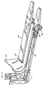
- Fig. 5 is a perspective view showing the lift mechanism for the lower forks, and the linkage rod controlling the position of the load wheels;
- Fig. 6 is a side elevational view of the truck showing the upper and lower forks nested and in their lowermost position;
- Fig. 7 is a side elevational view of the truck showing the upper and lower forks nested and in a raised position, sufficient to raise a pallet above the floor;
- Fig. 8 is a schematic of the hydraulic system for an embodiment of the present invention; and
- Fig. 9 is an electrical schematic diagram of the electrical system for an embodiment of the present invention.
-
- Referring now to the drawings which illustrate a preferred embodiment of this invention, and particularly to Figs. 1 and 2, an extended length
rider pallet truck 10 includes apower unit 15, which includes a motor (not shown) providing power to adrive wheel 20, aplatform 25 on which an operator may ride, acontrol handle 30 for controlling the direction and speed of the truck, anoperator grab bar 35 withfunction controls 40. A pair ofcastors 45 are placed outside the drive wheel. The truck is normally driven power unit first, or to the left as shown in Fig. 2, although the truck may also be moved in the reverse direction when desired. A bumper ordebris guard 50 is placed under the truck to protect thedrive wheel 20 and castors 45 from damage. - A pair of primary or
lower forks 60 are supported on a firstfork lifting mechanism 70 which can raise thelower forks 60 from their lowermost position to an upper level approximately 23 cms (9 ins) above the floor. The first fork lifting mechanism is a basic four-bar arrangement with a primary hydraulic cylinder 75 (Fig. 5) providing the lifting force. A typical pallet truck of this type can lift 2722 to 3629 kgs (6000 to 8000 1bs). - A
load wheel 80 is placed at the outer end of eachlower fork 60. The loadwheel lifting mechanism 85 includes arms 87 connected tolinkage rods 90 which cause the wheels to lower and support the lower forks as they are lifted. Abattery 100 is carried at theheel end 62 of the lower forks and will be raised and lowered with theforks 60. - A pair of secondary or
upper forks 110 are positioned above thelower forks 60 and are carried by a secondfork lifting mechanism 120 mounted on thelower forks 60. The second lifting mechanism includes amast structure 125 formed fromstationary channel members 130 and verticallymovable channel members 135 which are guided by rollers (not shown). A secondary hydraulic lift cylinder 140 (shown in Figs 1 and 8) provides lifting power sufficient to raise theupper forks 110 up to approximately 61 cms (24 ins) above thefloor 150. Avertical wall 155 is placed between theheel end 160 of theupper forks 110 and the lifting mechanism. -
Ends 170 of theupper forks 110 are stabilized by a secondfork supporting mechanism 180, including hydraulic cylinders, that are connected between the ends of the upper forks and theends 185 of thelower forks 60. It is to be understood that the stabilizinghydraulic cylinders 180 do not necessarily have to be connected to the ends of the upper forks, but it is preferred that they be connected to the ends of the lower forks since this provides a convenient mounting point. - The
upper forks 60 are shown as being double length, that is, they can support a pair of typical industry standard 102 to 123 cm (40 by 48 inch) pallets, but it is to be understood that the forks may be made longer, if desired. In some applications, the pallet length need only be as long as the narrow side of one pallet plus 75% of a second pallet. Thus, it is only required that the forks be of sufficient length to support at least two pallets. While only asingle pallet 200 is shown on theupper forks 110 in Fig. 1, it is to be understood that multiple, side-by-side pallets many be carried on the forks. As shown, thepallet 200 is a block style pallet that includes a plurality of blocks orlegs 202 that descend from anupper platform 204. The spacing betweenblocks 202 is standard and permits the forks of a pallet truck to pass freely therebetween. - As shown in the cross sectional views of Figs. 3 and 4, the
upper fork 110 is a C-shaped member provided with a reinforcingstrip 112. Ahydraulic line 210 from thepower unit 15 to the stabilizingcylinders 180 may be carried in the space formed between thestrip 112 and thefork 110. Thelower fork 60 is also provided with a reinforcingstrip 62. The inside dimension D1 of the upper fork is greater than the outside dimension D2 of thelower fork 60, thus allowing the two fork sections to nest. - In operation, the
forks - In Fig. 7, the forks are raised to a first position. This represents the upper level position of the forks of a conventional pallet truck, such as the Crown PE Series Rider Pallet Truck, when a
pallet 200 is placed on the forks. Theload wheel 80 is lowered by action of thelinkage rod 90, which is connected to the first lifting mechanism 70 (Fig. 5). In this position, the upper surface offorks 110 is about 23 cms (9 ins) above the floor, and thus the bottom of pallets carried on the forks will be clear of the floor, thus enabling the pallets to be moved. In this position, the load wheels are extended and support the outer ends of the forks, as is conventional with a PE Series Rider Pallet Truck. - When the
upper forks 110 are raised to their maximum height, as shown in Fig. 1, the upper surface of the forks will be approximately 61 cms (24 ins) or more above the floor. In this position, the operator may conveniently load the pallet from stock from racks adjacent the truck. The upper fork may be placed at any convenient height, from 23 to 61 cms (9 to 24 ins), depending on the desire of the operator. - A hydraulic schematic drawing of the improved pallet truck is shown in Fig. 8. This schematic is similar to the hydraulic schematic used in a conventional PE Series Pallet Truck but includes two additional features, namely a
secondary lift cylinder 140 and the two stabilizing orfork tip cylinders 180. Hydraulic fluid is provided to the system frompower unit 215, which includes a pump-motor unit, to amanifold 220. Thesecondary lift cylinder 140 will only be provided with hydraulic fluid after theprimary lift cylinder 75 has reached its height limit, as indicated by the dotted lines showing the upward movement of the primary lift cylinder engaging the limit switch LMS1. During downward movement, hydraulic pressure will be released from the primary lift cylinder only after the secondary lift cylinder has reached its lower travel limit, as indicated by the full line depection, and limit switch LMS2 is actuated.Hydraulic device 225, including flow divider valve FDV and valves SV4 and SV5, insures that both stabilizingcylinders 180 receive the same hydraulic flow. - The electrical schematic diagram of the truck is shown in Fig. 9. Power to the circuit is provided by the
battery 100 through fuses F1 and F2. When the operator closes the key switch KYS, battery power is made available to the fork raise switch RAS, the fork lower switch LOS and the brake switch BRS. Forward travel is controlled by forward travel switch FS and reverse travel is controlled by reverse travel switch RS. Switches RAS and LOS are available on the control handle 30 and controls 40 onoperator grab bar 35, the brake switch BRS is controlled by the vertical position of the control handle 30, and the forward and reverse switches are controlled by twist grips on the control handle. This electrical configuration is conventional on a Series PE Rider Pallet Truck. In addition, limit switch LMS1 is fully closed when the lower orprimary forks 60 are in their fully raised position, and limit switch LMS2 is shown with the upper orsecondary forks 110 in their home, or lowered or nested, position. - While the form of apparatus herein described constitutes a preferred embodiment of this invention, it is to be understood that the invention is not limited to this precise form of apparatus and that changes may be made therein without departing from the scope of the invention, which is defined in the appended claims.
Claims (9)
- A pallet truck (10) comprising a truck body, a first fork lifting mechanism (70) carried by said truck body, a pair of primary forks (60) having a first end attached to said first fork lifting mechanism (70), load wheels (80) positioned to support a second end of said primary forks (60), a pair of secondary forks (110) mounted above said primary forks (60), said secondary forks (110) having a first end and a second end, being mounted directly above said primary forks (60) and being configured to nest with said primary forks (60) when in their lower position, and a second fork lifting mechanism (120) for raising said first end of said secondary forks (110) from a lower position to a raised position, said pallet truck being characterised in that it further comprises:a load wheel lifting mechanism (85) responsive to the first fork lifting mechanism (70) for causing said second end of said primary forks (60) to be raised from a lower level to an upper level simultaneously with the raising of said first end thereby to maintain said primary forks (60) level,a support mechanism (180) attached to said secondary forks (110) at a location remote from said first end for supporting said second end of said secondary forks (110) while in a raised position, said support mechanism (180) including a support hydraulic cylinder (180) placed between each secondary fork (110) and its corresponding primary fork (60), anda hydraulic circuit for supplying hydraulic pressure to said support hydraulic cylinders (180).
- A pallet truck as claimed in claim 1, wherein said secondary forks (110) are of an extended length.
- A pallet truck as claimed in claim 1 or 2, wherein said second fork lifting mechanism (120) comprises a hydraulic lifting cylinder (140) and said hydraulic circuit supplies hydraulic pressure to said hydraulic lifting cylinder (140) and said support hydraulic cylinders (180) so that said secondary forks (110) are supported from their lower position to their fully raised position.
- A pallet truck as claimed in claim 1, 2 or 3, wherein said support hydraulic cylinders (180) are connected between the ends of said primary forks (60) and the ends of said secondary forks (110)
- A pallet truck as claimed in claim 1, 2 or 3, wherein said support mechanism (180) is attached to said secondary forks (110) at or near the end thereof.
- A pallet truck as claimed in any preceding claim, wherein said second fork lifting mechanism (120) is carried by said primary forks (60).
- A pallet truck as claimed in any preceding claim, wherein said secondary forks (110) have a lengh equal to or greater than that needed to support at least two industry standard pallets (200).
- A pallet truck as claimed in any preceding claim, wherein the length of said pair of secondary forks (110) is at least approximately 183 cm (72 ins).
- A method of order selecting using a pallet truck (10), as claimed in any preceding claim, provided with said secondary forks (110) of extended length capable of supporting multiple side-by-side pallets (200), the method including the steps of :-characterized in that said first end is raised in excess of 30 cms (12 ins) above the floor (150); and said support mechanism (180) is provided to the secondary forks (110) at said location remote from said first end while in the raised position to provide a stable platform while items are accumulated on the pallets (200).placing one or more pallets (200) on the secondary forks (110);raising said first end of the secondary forks (110) above the floor (150),lowering the secondary forks (110) to place the pallets (200) in contact with the floor (150); andbacking the pallet truck from under the loaded pallets (200);
Applications Claiming Priority (3)
| Application Number | Priority Date | Filing Date | Title |
|---|---|---|---|
| US41555695A | 1995-04-03 | 1995-04-03 | |
| US415556 | 1995-04-03 | ||
| PCT/US1996/003109 WO1996031431A1 (en) | 1995-04-03 | 1996-03-06 | Auxiliary lifting forks for extended-length pallet trucks |
Publications (3)
| Publication Number | Publication Date |
|---|---|
| EP0820420A1 EP0820420A1 (en) | 1998-01-28 |
| EP0820420A4 EP0820420A4 (en) | 1999-04-14 |
| EP0820420B1 true EP0820420B1 (en) | 2003-05-28 |
Family
ID=23646176
Family Applications (1)
| Application Number | Title | Priority Date | Filing Date |
|---|---|---|---|
| EP96908697A Expired - Lifetime EP0820420B1 (en) | 1995-04-03 | 1996-03-06 | Auxiliary lifting forks for extended-length pallet trucks |
Country Status (5)
| Country | Link |
|---|---|
| US (1) | US5752584A (en) |
| EP (1) | EP0820420B1 (en) |
| CA (1) | CA2216472A1 (en) |
| DE (1) | DE69628428T2 (en) |
| WO (1) | WO1996031431A1 (en) |
Families Citing this family (59)
| Publication number | Priority date | Publication date | Assignee | Title |
|---|---|---|---|---|
| SE506507C2 (en) * | 1995-05-24 | 1997-12-22 | Sven Nordstroem | Low lift truck with vertically rotatable movable drive wheels for avoiding heels when passing unevenness in the ground |
| DE19741764C1 (en) * | 1997-09-22 | 1999-04-22 | Ice Cargo Equipment Ag | Pallet truck |
| JP2001003770A (en) * | 1999-06-16 | 2001-01-09 | Unisia Jecs Corp | Electric throttle valve device |
| JP2001002380A (en) * | 1999-06-25 | 2001-01-09 | Tsubakimoto Chain Co | Control method and device for lifting system |
| AUPR689201A0 (en) * | 2001-08-09 | 2001-08-30 | Lear, Adam Thomas | Bed bug |
| WO2003091150A1 (en) * | 2002-04-23 | 2003-11-06 | Crown Equipment Corporation | Work assist accessory for pallet trucks and pallet trucks including work assist features |
| US7191872B2 (en) * | 2002-11-22 | 2007-03-20 | The Raymond Corporation | Fork height adjustment mechanism |
| ATE340117T1 (en) * | 2003-04-23 | 2006-10-15 | Borrmann Gmbh | FORK PALLET TRUCKS |
| US7165776B2 (en) * | 2003-05-22 | 2007-01-23 | Crown Equipment Corporation | Pivotable tray for a pallet truck |
| US20050036880A1 (en) * | 2003-08-07 | 2005-02-17 | Magoto Daniel Carl | Pallet truck with reinforced fork weldment |
| US7326022B2 (en) * | 2004-11-30 | 2008-02-05 | Brown James C | Tow trailer assembly |
| EP2102092B1 (en) * | 2007-01-08 | 2014-04-16 | Bishamon Industries Corporation | Lift for skids and pallets |
| US7568708B2 (en) * | 2007-02-21 | 2009-08-04 | Vietri Jr Gesualdo | Pallet truck steer wheel safety guard |
| US8454037B2 (en) | 2007-06-15 | 2013-06-04 | Crown Equipment Corporation | Outrigger assembly with quick change load wheel assembly |
| US7845657B2 (en) * | 2007-06-15 | 2010-12-07 | Crown Equipment Corporation | Quick change load wheel assembly |
| US20090279994A1 (en) * | 2008-05-07 | 2009-11-12 | Ivan Kirilov Gramatikov | Fork assembly lift mechanism |
| WO2010008326A1 (en) * | 2008-07-18 | 2010-01-21 | Akromet Ab | Fork pallet truck |
| US8282111B2 (en) | 2008-10-20 | 2012-10-09 | Magline, Inc. | Cart with movable platform |
| US20110171000A1 (en) * | 2010-01-11 | 2011-07-14 | Magline Incorporated | Walkie-rider tine attachment |
| US9045321B2 (en) * | 2010-01-15 | 2015-06-02 | Recon Engineering, Inc. | Load transport system and method |
| US8651797B2 (en) | 2010-09-27 | 2014-02-18 | Crown Equipment Corporation | Backrest assembly for a materials handling vehicle |
| US8888110B2 (en) | 2011-11-15 | 2014-11-18 | Polymer Logistics (Israel) Ltd. | Pallet dolly |
| US9045253B2 (en) | 2011-11-15 | 2015-06-02 | Polymer Logistics (Israel) Ltd. | Pallet-dolly |
| CN102515056A (en) | 2011-12-15 | 2012-06-27 | 浙江中力机械有限公司 | Carrier |
| USD692202S1 (en) | 2012-01-31 | 2013-10-22 | Big Lift, Llc | Pallet truck |
| US9403547B2 (en) * | 2012-02-24 | 2016-08-02 | Coca-Cola Bottling Co. United, Inc. | Pallet transportation assembly and processes of transporting pallets using the same |
| USD729488S1 (en) | 2013-08-14 | 2015-05-12 | Crown Equipment Corporation | Pallet |
| US9586605B2 (en) | 2013-10-16 | 2017-03-07 | Big Lift, Llc | Powered pallet truck |
| USD739112S1 (en) | 2013-10-16 | 2015-09-15 | Big Lift, Llc | Powered pallet truck |
| US10040674B2 (en) | 2013-12-17 | 2018-08-07 | Big Lift, Llc | Cart with height adjustable platform and methods of using the same |
| MX2015000527A (en) * | 2014-01-12 | 2015-08-20 | Rehrig Pacific Co | Pallet lift. |
| US9475513B2 (en) | 2014-07-25 | 2016-10-25 | Big Lift, Llc | Pallet truck |
| CN104309668A (en) * | 2014-09-30 | 2015-01-28 | 张冬梅 | Moving lift car |
| USD754415S1 (en) | 2014-10-15 | 2016-04-19 | Big Lift, Llc | Pallet truck |
| WO2016073427A1 (en) | 2014-11-05 | 2016-05-12 | Crown Equipment Corporation | Pallet truck with integrated half-size pallet support |
| USD767236S1 (en) | 2015-02-05 | 2016-09-20 | Big Lift, Llc. | Pallet truck |
| US10822011B2 (en) * | 2016-09-07 | 2020-11-03 | UniCarriers Americas Corporation | Pallet truck with pressed fork structure |
| US11254342B2 (en) | 2016-10-25 | 2022-02-22 | Rehrig Pacific Company | Delivery sled brake system |
| US10618539B2 (en) * | 2017-03-03 | 2020-04-14 | Hyster-Yale Group, Inc. | Adjustable load wheel |
| IT201700109338A1 (en) * | 2017-09-29 | 2019-03-29 | Zonzini S R L | TRACKED PALLET TROLLEY. |
| US10850759B2 (en) * | 2018-04-03 | 2020-12-01 | GPS, Inc. | Pallet truck wheel assembly toe guard |
| USD872965S1 (en) | 2018-04-17 | 2020-01-14 | Zhejiang E-P Equipment Co., Ltd. | Pallet truck |
| USD874083S1 (en) | 2018-04-18 | 2020-01-28 | Zhejiang E-P Equpiment Co., Ltd. | Pallet truck |
| SE544238C2 (en) * | 2018-04-23 | 2022-03-08 | Toyota Mat Handling Manufacturing Sweden Ab | Material handling vehicle |
| US10974749B2 (en) | 2018-04-23 | 2021-04-13 | Overhead Door Corporation | Trolley and method for moving long pallets |
| US11235963B2 (en) * | 2018-11-21 | 2022-02-01 | Hyster-Yale Group, Inc. | Forks for industrial vehicles and method of making same |
| US12397836B2 (en) * | 2019-03-27 | 2025-08-26 | Hyster-Yale Materials Handling, Inc. | Modular fork assembly for a forked material-handling vehicle |
| EP3962795B1 (en) * | 2019-04-30 | 2024-03-27 | Claudio Zonzini | Pallet truck |
| US11738790B2 (en) | 2020-03-10 | 2023-08-29 | Crown Equipment Corporation | Wheel guard |
| MX2025001831A (en) * | 2020-08-14 | 2025-03-07 | Rehrig Pacific Co | Pallet sled |
| USD975396S1 (en) | 2020-10-14 | 2023-01-10 | Zhejiang E-P Equipment Co., Ltd. | Pallet truck |
| EP4284748A1 (en) | 2021-01-29 | 2023-12-06 | Crown Equipment Corporation | Work assist system for an industrial vehicle |
| CN113929023B (en) * | 2021-08-26 | 2023-04-21 | 上海安能聚创物流科技有限公司 | Be applicable to big discharge device of storage commodity circulation |
| US11873020B2 (en) * | 2021-11-12 | 2024-01-16 | Rehrig Pacific Company | Delivery systems for ramps or stairs |
| US12570347B2 (en) | 2022-03-24 | 2026-03-10 | Rehrig Pacific Company | Hub motor with integrated brake |
| CN116040538B (en) * | 2023-03-21 | 2023-10-27 | 泰州鑫宇精工股份有限公司 | A board is placed in easy dismouting for fork truck |
| US12265400B1 (en) | 2023-12-27 | 2025-04-01 | Niagara Bottling, Llc | Facility layout |
| US12275606B1 (en) | 2023-12-27 | 2025-04-15 | Niagara Bottling, Llc | Facility layout |
| US12509338B2 (en) * | 2024-03-27 | 2025-12-30 | Hyster-Yale Materials Handling, Inc. | Auxiliary rollers for a fork of a forked materials-handling vehicle |
Family Cites Families (10)
| Publication number | Priority date | Publication date | Assignee | Title |
|---|---|---|---|---|
| US1432299A (en) * | 1919-05-09 | 1922-10-17 | Lakewood Engineering Company | Industrial truck |
| US1407124A (en) * | 1920-08-24 | 1922-02-21 | William C Carr | Elevator truck |
| US1497085A (en) * | 1921-02-15 | 1924-06-10 | Brandt Edgar William | Lifting truck |
| US2520857A (en) * | 1946-11-19 | 1950-08-29 | Irvin F Schreck | Lift truck |
| FR1263683A (en) * | 1960-07-29 | 1961-06-09 | Von Roll Ag | Pump unit for pallet lift trucks |
| GB1075742A (en) * | 1964-03-24 | 1967-07-12 | Lansing Bagnall Ltd | Improvements in or relating to industrial trucks |
| SE440480B (en) * | 1983-06-20 | 1985-08-05 | Idux Ind Exploatering Ab | TRUCK FOR HANDLING OF GOODS |
| SE449352B (en) * | 1984-11-28 | 1987-04-27 | Bertil Persson | LIFTING DEVICE, PREFERRED A DRIVER, WHO PREFERRED TO BE LIFTABLE AND MOVABLE WITH A LIFT WAGON |
| FR2574773B1 (en) * | 1984-12-17 | 1988-02-26 | Inst Textile De France | TROLLEY FOR RECEIVING AND TRANSPORTING A KNITTED PIECE FOR CIRCULAR MATERIALS |
| SE501093C2 (en) * | 1991-10-16 | 1994-11-14 | Scandinavian Airlines System S | Procedure and apparatus for loading and unloading goods in confined spaces such as cargo hold in aircraft |
-
1996
- 1996-03-06 CA CA002216472A patent/CA2216472A1/en not_active Abandoned
- 1996-03-06 EP EP96908697A patent/EP0820420B1/en not_active Expired - Lifetime
- 1996-03-06 WO PCT/US1996/003109 patent/WO1996031431A1/en not_active Ceased
- 1996-03-06 DE DE69628428T patent/DE69628428T2/en not_active Expired - Lifetime
- 1996-11-25 US US08/755,710 patent/US5752584A/en not_active Expired - Lifetime
Also Published As
| Publication number | Publication date |
|---|---|
| CA2216472A1 (en) | 1996-10-10 |
| DE69628428D1 (en) | 2003-07-03 |
| EP0820420A1 (en) | 1998-01-28 |
| WO1996031431A1 (en) | 1996-10-10 |
| EP0820420A4 (en) | 1999-04-14 |
| US5752584A (en) | 1998-05-19 |
| DE69628428T2 (en) | 2004-03-18 |
Similar Documents
| Publication | Publication Date | Title |
|---|---|---|
| US5752584A (en) | Auxiliary lifting forks for double-length pallet trucks | |
| US7744335B1 (en) | Pallet jack with independently elevatable fork arms | |
| EP2159185B1 (en) | Industrial truck comprising two load carriages | |
| US20020110447A1 (en) | Cantilevered, self-adjusting pneumatic pallet positioner | |
| US20050042068A1 (en) | Forklift with stabilizing forks | |
| US5417541A (en) | Manual forklift pallet jack for unloading the contents of a beverage delivery truck | |
| US2958436A (en) | Article handling method and apparatus | |
| EP2825497B1 (en) | Order pickers | |
| US7665949B2 (en) | Carton handling method and apparatus | |
| US2910204A (en) | Industrial lift truck | |
| GB2104052A (en) | Handling storage units, e.g. pallets | |
| US11117790B2 (en) | Industrial truck comprising a thrust device | |
| US6648581B2 (en) | Order picker truck | |
| EP0280828B1 (en) | Load elevator | |
| US6079935A (en) | Forklift truck | |
| MX2009000351A (en) | Racking system and method of storing palletized items. | |
| WO2020228055A1 (en) | Drive-in jacking and carrying trackless shuttle vehicle and application thereof | |
| AU2005304275A1 (en) | Layered package handling method and apparatus | |
| GR20180100396A (en) | Lightweight small-sized load elevator-transporter | |
| WO1995030618A1 (en) | Forklift with fork support | |
| US5330306A (en) | Pallet handling platten unit | |
| CN215099843U (en) | Shuttle type goods shelves in high-efficient utilization space | |
| CN218908015U (en) | Self-transportation tray device | |
| CN218560991U (en) | Hydraulic carrying trolley | |
| CN216185049U (en) | Liftable goods railway carriage or compartment |
Legal Events
| Date | Code | Title | Description |
|---|---|---|---|
| PUAI | Public reference made under article 153(3) epc to a published international application that has entered the european phase |
Free format text: ORIGINAL CODE: 0009012 |
|
| 17P | Request for examination filed |
Effective date: 19971030 |
|
| AK | Designated contracting states |
Kind code of ref document: A1 Designated state(s): BE DE FR GB IE IT SE |
|
| A4 | Supplementary search report drawn up and despatched |
Effective date: 19990301 |
|
| AK | Designated contracting states |
Kind code of ref document: A4 Designated state(s): BE DE FR GB IE IT SE |
|
| 17Q | First examination report despatched |
Effective date: 20010523 |
|
| GRAH | Despatch of communication of intention to grant a patent |
Free format text: ORIGINAL CODE: EPIDOS IGRA |
|
| GRAH | Despatch of communication of intention to grant a patent |
Free format text: ORIGINAL CODE: EPIDOS IGRA |
|
| GRAA | (expected) grant |
Free format text: ORIGINAL CODE: 0009210 |
|
| AK | Designated contracting states |
Designated state(s): BE DE FR GB IE IT SE |
|
| PG25 | Lapsed in a contracting state [announced via postgrant information from national office to epo] |
Ref country code: IT Free format text: LAPSE BECAUSE OF FAILURE TO SUBMIT A TRANSLATION OF THE DESCRIPTION OR TO PAY THE FEE WITHIN THE PRE;WARNING: LAPSES OF ITALIAN PATENTS WITH EFFECTIVE DATE BEFORE 2007 MAY HAVE OCCURRED AT ANY TIME BEFORE 2007. THE CORRECT EFFECTIVE DATE MAY BE DIFFERENT FROM THE ONE RECORDED.SCRIBED TIME-LIMIT Effective date: 20030528 Ref country code: BE Free format text: LAPSE BECAUSE OF FAILURE TO SUBMIT A TRANSLATION OF THE DESCRIPTION OR TO PAY THE FEE WITHIN THE PRESCRIBED TIME-LIMIT Effective date: 20030528 |
|
| REG | Reference to a national code |
Ref country code: GB Ref legal event code: FG4D |
|
| REG | Reference to a national code |
Ref country code: IE Ref legal event code: FG4D |
|
| REF | Corresponds to: |
Ref document number: 69628428 Country of ref document: DE Date of ref document: 20030703 Kind code of ref document: P |
|
| PG25 | Lapsed in a contracting state [announced via postgrant information from national office to epo] |
Ref country code: SE Free format text: LAPSE BECAUSE OF FAILURE TO SUBMIT A TRANSLATION OF THE DESCRIPTION OR TO PAY THE FEE WITHIN THE PRESCRIBED TIME-LIMIT Effective date: 20030828 |
|
| PG25 | Lapsed in a contracting state [announced via postgrant information from national office to epo] |
Ref country code: IE Free format text: LAPSE BECAUSE OF NON-PAYMENT OF DUE FEES Effective date: 20040308 |
|
| ET | Fr: translation filed | ||
| PLBE | No opposition filed within time limit |
Free format text: ORIGINAL CODE: 0009261 |
|
| STAA | Information on the status of an ep patent application or granted ep patent |
Free format text: STATUS: NO OPPOSITION FILED WITHIN TIME LIMIT |
|
| 26N | No opposition filed |
Effective date: 20040302 |
|
| REG | Reference to a national code |
Ref country code: IE Ref legal event code: MM4A |
|
| PGFP | Annual fee paid to national office [announced via postgrant information from national office to epo] |
Ref country code: GB Payment date: 20090325 Year of fee payment: 14 |
|
| GBPC | Gb: european patent ceased through non-payment of renewal fee |
Effective date: 20100306 |
|
| PG25 | Lapsed in a contracting state [announced via postgrant information from national office to epo] |
Ref country code: GB Free format text: LAPSE BECAUSE OF NON-PAYMENT OF DUE FEES Effective date: 20100306 |
|
| REG | Reference to a national code |
Ref country code: FR Ref legal event code: PLFP Year of fee payment: 20 |
|
| PGFP | Annual fee paid to national office [announced via postgrant information from national office to epo] |
Ref country code: DE Payment date: 20150320 Year of fee payment: 20 |
|
| PGFP | Annual fee paid to national office [announced via postgrant information from national office to epo] |
Ref country code: FR Payment date: 20150319 Year of fee payment: 20 |
|
| REG | Reference to a national code |
Ref country code: DE Ref legal event code: R071 Ref document number: 69628428 Country of ref document: DE |
|
| P01 | Opt-out of the competence of the unified patent court (upc) registered |
Effective date: 20230529 |