EP0820367B1 - Modular storage and transportation system of tools and materials - Google Patents
Modular storage and transportation system of tools and materials Download PDFInfo
- Publication number
- EP0820367B1 EP0820367B1 EP97902737A EP97902737A EP0820367B1 EP 0820367 B1 EP0820367 B1 EP 0820367B1 EP 97902737 A EP97902737 A EP 97902737A EP 97902737 A EP97902737 A EP 97902737A EP 0820367 B1 EP0820367 B1 EP 0820367B1
- Authority
- EP
- European Patent Office
- Prior art keywords
- module
- pivot
- pivot shaft
- tools
- modules
- Prior art date
- Legal status (The legal status is an assumption and is not a legal conclusion. Google has not performed a legal analysis and makes no representation as to the accuracy of the status listed.)
- Expired - Lifetime
Links
Images


Classifications
-
- B—PERFORMING OPERATIONS; TRANSPORTING
- B65—CONVEYING; PACKING; STORING; HANDLING THIN OR FILAMENTARY MATERIAL
- B65D—CONTAINERS FOR STORAGE OR TRANSPORT OF ARTICLES OR MATERIALS, e.g. BAGS, BARRELS, BOTTLES, BOXES, CANS, CARTONS, CRATES, DRUMS, JARS, TANKS, HOPPERS, FORWARDING CONTAINERS; ACCESSORIES, CLOSURES, OR FITTINGS THEREFOR; PACKAGING ELEMENTS; PACKAGES
- B65D21/00—Nestable, stackable or joinable containers; Containers of variable capacity
- B65D21/08—Containers of variable capacity
- B65D21/083—Containers of variable capacity by means of additional elements, e.g. modular
-
- B—PERFORMING OPERATIONS; TRANSPORTING
- B25—HAND TOOLS; PORTABLE POWER-DRIVEN TOOLS; MANIPULATORS
- B25H—WORKSHOP EQUIPMENT, e.g. FOR MARKING-OUT WORK; STORAGE MEANS FOR WORKSHOPS
- B25H3/00—Storage means or arrangements for workshops facilitating access to, or handling of, work tools or instruments
- B25H3/02—Boxes
- B25H3/021—Boxes comprising a number of connected storage elements
- B25H3/023—Boxes comprising a number of connected storage elements movable relative to one another for access to their interiors
- B25H3/025—Boxes comprising a number of connected storage elements movable relative to one another for access to their interiors by rotation about a common axis
-
- E—FIXED CONSTRUCTIONS
- E05—LOCKS; KEYS; WINDOW OR DOOR FITTINGS; SAFES
- E05D—HINGES OR SUSPENSION DEVICES FOR DOORS, WINDOWS OR WINGS
- E05D7/00—Hinges or pivots of special construction
- E05D7/10—Hinges or pivots of special construction to allow easy separation or connection of the parts at the hinge axis
- E05D7/1061—Hinges or pivots of special construction to allow easy separation or connection of the parts at the hinge axis in a radial direction
- E05D7/1077—Hinges or pivots of special construction to allow easy separation or connection of the parts at the hinge axis in a radial direction with snap-fitted pins
-
- E—FIXED CONSTRUCTIONS
- E05—LOCKS; KEYS; WINDOW OR DOOR FITTINGS; SAFES
- E05Y—INDEXING SCHEME RELATING TO HINGES OR OTHER SUSPENSION DEVICES FOR DOORS, WINDOWS OR WINGS AND DEVICES FOR MOVING WINGS INTO OPEN OR CLOSED POSITION, CHECKS FOR WINGS AND WING FITTINGS NOT OTHERWISE PROVIDED FOR, CONCERNED WITH THE FUNCTIONING OF THE WING
- E05Y2900/00—Application of doors, windows, wings or fittings thereof
- E05Y2900/60—Application of doors, windows, wings or fittings thereof for other use
- E05Y2900/602—Application of doors, windows, wings or fittings thereof for other use for containers
Definitions
- the invention concerns a device for storage and transport of tools and materials, consisting of modules, as described in the pre-characterizing part of Claim 1.
- a device for storage and transport of tools and materials, consisting of modules, as described in the pre-characterizing part of Claim 1.
- Such a device is known from the document EP-A-566983.
- Many other systems for storage and transport of tools are known.
- There are metal toolboxes that can be characterised by a limited overview of the content and a high weight.
- plastic toolboxes with a division in compartments and trays that characteristically have a limited overview and a limited capacity.
- toolboxes in which the tools are not stored in trays, but are fixed onto boards in an organised way, often by means of sleeve pockets, clamps or straps.
- Coupling and uncoupling of the modules is done by using a separate pivot pin having a relatively small diameter and a length substantially equal to the length of a module and passing through a number of pivot casings, so that one cannot speak of an easy (un)coupling of the modules.
- a unit, composed of modules, is meant to be used laying flat. If the modules on top contain heavy tools or materials, this leads to backward topping over of the unit. In addition, these heavy modules must be lifted every time the content of the modules underneath must be reached.
- US-A-5217115 discloses a reusable tool packaging system of complementary plastic planar members snapfit together and interlocked therebetween to allow a planar assembly or a configuration akin to a toolbox.
- complementary extruded plastic planar members can be used for hanging the planar assembly with one side, forming the outer side of the system in the toolbox configuration, flat on a wall.
- WO-A-90/08631 discloses a portable carrier for hand tools having an open frame member with two cover parts. Pivotally attached between the open frame member and a cover part is a plane on which tools or materials can be fixed on both sides.
- the invention is aimed at providing a system for storage and transportation of tools and materials that is compact, well-organised and accessible under all circumstances, and the capacity of which can easily be adapted. According to the invention, this is achieved by the features of the characterizing part of claim 1 resulting in the possibility to couple modules in such a way that they can pivot with respect to each other, while on the other hand they can be hung on the wall separately, whereas each module has a plane on which tools or materials can be fixed from both sides. According to one preferred embodiment of the coupling means, described in Claim 2, coupling of the modules can be done in a user-friendly manner, so that it is possible to assemble a compact mobile unit, containing the right tools for a certain job, easily and quickly.
- each module may be equipped with small castors or elements of comparable function, so that when a number of modules is assembled to form a unit, the unit is moveable as a cart.
- the castor wheels allow easy movement of the modules with respect to each other, so that each module is easily accessible from both sides.
- a unit, consisting of one or more modules, can be closed by means of covers to protect the content from environmental influences and from damage.
- Each module can be equipped with a handle in such a way, that an assembled unit can be carried with one hand.
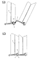
- the user can disassemble the unit at home or in the workshop easily, and hang the modules on the wall separately besides each other.
- a large number of tools can be stored on a relatively small wall surface, maintaining overview and accessibility.
- the tools can be fixed to the plane of the modules by means of suitable clamps or, more specifically, by means of a clamping system that holds each tool between two concave shoes or holders while clamping it axially through spring action.
- the tool holders are fixed to the perforated plane 3 by means of snap fingers.
- Figure 9 shows the top holder 17
- Figure 10 shows the lower holder 18.
- the top holder consits of a concave shoe 22 that is connected through a straight guidance to a guiding block 19 by means of calliper 23.
- the guiding block 19 is fixed to the perforated surface 3 by means of two snap fingers 20 and 21.
- the guiding block 19 can be moved up and down with respect to calliper 23.
- Two springs 24 deliver the spring force for the system.
- the lower holder 18 consists of a shoe 30, comparable to 22 to the extent that this shoe 30 is bevelled at the front side. In the shoe 30, two shafts 28 and 29 are mounted, that take care of a straight guidance in guiding block 25.
- the guiding block 25 can be fixed to plane 3 by means of snap fingers 26 and 27.
- the lower holder 18 has no springs, but is adjustable in height by means of adjusting bolt 31, so that the above described clamping of the tools can also be applied otherwise.
Abstract
Description
Many other systems for storage and transport of tools are known. There are metal toolboxes that can be characterised by a limited overview of the content and a high weight. There are plastic toolboxes with a division in compartments and trays that characteristically have a limited overview and a limited capacity. Finally there are toolboxes in which the tools are not stored in trays, but are fixed onto boards in an organised way, often by means of sleeve pockets, clamps or straps. These boxes have a limited capacity and are not easy to use for heavy tools, because the boards are then difficult to move over or because the the box will then overturn or fall shut. There also exist extendable, modular systems, as described in documents DE-A-42.28.370, DE-U-92.055.444 and DE-U-93.16.766. As opposed to the present invention, the content of the modules of the abovementioned systems is accessible only after the modules have been disconnected. The modularity or extendability is exclusively aimed at transportation and not at utilisation. Other patents regarding toolboxes concern a number of modules that can rotate or pivot with respect to each other, as in the documents US-A 5.259.502, DE-U-91.02.718, CH-A-447.075, US-A-4.998.616, WO-A-90/08631 and EP-A-0.319.969, but these documents do not include the possibility to easily couple any number of modules that can pivot with respect to each other, nor do they include the possibility to mount the modules separately to the wall, in such a way that they can swung around.
The device known from the document EP-A-566983 has great limitations for the user. Coupling and uncoupling of the modules is done by using a separate pivot pin having a relatively small diameter and a length substantially equal to the length of a module and passing through a number of pivot casings, so that one cannot speak of an easy (un)coupling of the modules. A unit, composed of modules, is meant to be used laying flat. If the modules on top contain heavy tools or materials, this leads to backward topping over of the unit.
In addition, these heavy modules must be lifted every time the content of the modules underneath must be reached.
A do-it-yourselfer, a carpenter or a mechanic who uses his tools at home respectively in his workshop as well as elsewhere, wants a storage system for his tools that is well organised and has sufficient capacity, so that he can store all his tools in it and can find each tool easily. A user with few tools does not need much storage capacity, and wants a compact, but extendable, system. Someone who works at home or in a workshop, and also goes out to do jobs elsewhere, wants a storage system for his tools that remains well-organised in all situations. He wants to fix his tools to the wall above his workbench at home so that his doesn't have to bend down during work. Going to a job, he only wants to take the tools he needs, because he doesn't like to carry too many tools in view of the generally high weight. At the jobsite, he wants a compact and well-organised unit, in which he can find his tools easily without going through trays full of tools. When the job is done, he wants to store his tools at home directly, without having to fix each tool separately.
According to the invention, this is achieved by the features of the characterizing part of claim 1 resulting in the possibility to couple modules in such a way that they can pivot with respect to each other, while on the other hand they can be hung on the wall separately, whereas each module has a plane on which tools or materials can be fixed from both sides.
According to one preferred embodiment of the coupling means, described in
The invention will be explained in more detail using a number of design examples.
Claims (16)
- A device for storage and transportation of tools and materials, said device comprising at least one module (1) that can be coupled to an adjacent module (1) and that comprises coupling means (5, 6) permitting a plurality of said modules to be coupled in any sequence, such that in a coupled position each of the plurality of said modules can pivot with respect to an adjacent module, characterized in that each module comprises a plane (3) on which tools or materials can be fixed on both sides thereof, and an open frame member (2) surrounding and supporting said plane and having a stiffening structure containing the coupling means (5, 6), that can additionally support each module separated from other modules in a hanging position secured to a wall (10), in which the separate module is coupled to a wall mounted holder (9) such that the separate module can pivot about a vertical axis with respect to said wall mounted holder.
- A device according to claim 1, characterized in that the coupling means comprises a set of pivot shaft means (5) with a first pivot axis and a set of pivot casing means (6) with a second pivot axis extending spaced and parallel to the first pivot axis, in the coupled position the set of pivot shaft means or the set of pivot casing means of a module (1) being coupled with the set of pivot casing means or the set of pivot shaft means of an adjacent module (1) and in the hanging position one of said sets being coupled with the wall mounted holder (9).
- A device according to claim 2, characterized in that in the hanging position the set of pivot shaft means (5) is used for coupling the module to the wall-mounted holder (9).
- A device according to claim 2 or 3, characterized in that the set of pivot casing means (6) comprises at least one pivot shaft bearing casing with a lateral opening for inserting a pivot shaft of the set of pivot shaft means (5), and a cam (15) that can be turned from a pivot shaft inserting position to an pivot shaft locking position.
- A device according to claim 4, characterized in that the cam (15) is spring loaded in the direction of the pivot shaft locking position.
- A device according to any one of claims 2-5, characterized in that the open frame member (2) has a substantially rectangular configuration, the set of pivot shaft means (5) being fixably attached along the peripheral edge of one of the sides of the frame member and the set of pivot casing means (6) to the opposing peripheral edge of said side of the frame member.
- A device according to claim 6, characterized in that in the pivotally closed position the open frame members (2) form a closed peripheral wall.
- A device according to claim 6 or 7, characterized in that a side of the frame member (2) perpendicular to the side carrying the coupling means (5, 6) is provided with castors or devices with a comparable function.
- A device according to any one of the preceding claims, characterized in that releasable closures (8) are present to block pivoting of the modules (1) with respect to each other in the coupled and pivotally closed position.
- A device according to any one of claims 4-9, characterized in that disengagement of coupled modules is achieved by turning the cam (15) from the pivot shaft locking position to the pivot shaft inserting position by a single-handedly operated transmission mechanism.
- A device according to any one of the preceding claims, characterized in that each module is provided with means for attaching a carrying belt or shoulder belt.
- A device according to any one of the preceding claims,
characterized in that the above mentioned plane (3) is provided with a large number of holes in a regular pattern, in which clamps or holders for tools or materials can be fixed. - A device according to any one of the preceding claims,
characterized in that the above mentioned clamps or holders can be fixed in the appropriate holes of plane (3) by means of snap fingers that are mounted on, or are part of, these clamps or holders. - A device according to any one of the preceding claims,
characterized in that the modules are made of plastic by means of an injection moulding process. - A device according to any one of the preceding claims,
characterized in that the tools or the materials that are stored therein, can be fixed by means of clamping devices, each consisting of two holders (17) and (18) between which the tool or material is clamped through an axial clamping between the concave shoes (22) and (23) that, spring loaded or not, can move axially with respect to each other. - A device according to any one of the preceding claims,
characterized in that the above described clamping devices for tools or materials are made in such a way, that one concave shoe (22) is movable against spring action, and the other concave shoe (30) is not spring loaded, and can be fixed with respect to the other concave shoe (22) by means of one or more adjusting screws.
Applications Claiming Priority (3)
| Application Number | Priority Date | Filing Date | Title |
|---|---|---|---|
| NL1002290 | 1996-02-09 | ||
| NL1002290A NL1002290C2 (en) | 1996-02-09 | 1996-02-09 | Modular storage and transport system for tools and materials. |
| PCT/NL1997/000048 WO1997028931A1 (en) | 1996-02-09 | 1997-02-10 | Modular storage and transportation system of tools and materials |
Publications (2)
| Publication Number | Publication Date |
|---|---|
| EP0820367A1 EP0820367A1 (en) | 1998-01-28 |
| EP0820367B1 true EP0820367B1 (en) | 2004-08-18 |
Family
ID=19762274
Family Applications (1)
| Application Number | Title | Priority Date | Filing Date |
|---|---|---|---|
| EP97902737A Expired - Lifetime EP0820367B1 (en) | 1996-02-09 | 1997-02-10 | Modular storage and transportation system of tools and materials |
Country Status (8)
| Country | Link |
|---|---|
| US (1) | US5984441A (en) |
| EP (1) | EP0820367B1 (en) |
| AT (1) | ATE273772T1 (en) |
| AU (1) | AU1675497A (en) |
| DE (1) | DE69730279T2 (en) |
| ES (1) | ES2227668T3 (en) |
| NL (1) | NL1002290C2 (en) |
| WO (1) | WO1997028931A1 (en) |
Families Citing this family (37)
| Publication number | Priority date | Publication date | Assignee | Title |
|---|---|---|---|---|
| US6213313B1 (en) * | 1998-06-12 | 2001-04-10 | Raymond H. Levy | Paint chip display system |
| US6374547B1 (en) | 1998-10-30 | 2002-04-23 | Steelcase Development Inc. | Workstation |
| US6272779B1 (en) | 1998-10-30 | 2001-08-14 | Steelcase Development Inc. | Display board system |
| US6463701B1 (en) | 1998-10-30 | 2002-10-15 | Steelcase Development Corporation | Work environment |
| US6647652B1 (en) | 1998-10-30 | 2003-11-18 | Steelcase Development Inc. | Display board system |
| US6540094B1 (en) * | 1998-10-30 | 2003-04-01 | Steelcase Development Corporation | Information display system |
| US6892650B2 (en) * | 2001-06-22 | 2005-05-17 | Steelcase Development Corporation | Movable display support system |
| US6279761B1 (en) | 1999-03-01 | 2001-08-28 | Steelcase Development Inc. | Information display system |
| IL129040A0 (en) * | 1999-03-18 | 2000-02-17 | Tsachi Davidov | Disk holder |
| US6578718B2 (en) * | 2000-05-01 | 2003-06-17 | Raymond H. Levy | Paint chip display system |
| US7165674B2 (en) | 2004-02-18 | 2007-01-23 | Black & Decker Inc. | Storage container |
| US6739096B2 (en) | 2001-06-22 | 2004-05-25 | Steelcase Development Corporation | Movable office support system |
| US6648166B2 (en) | 2001-07-19 | 2003-11-18 | Zag Industries Ltd. | Folding storage assembly |
| US7219969B2 (en) * | 2003-02-27 | 2007-05-22 | Zag Industries Ltd. | Storage container and storage system including a stack of the same |
| US6945546B2 (en) | 2003-09-19 | 2005-09-20 | Guirlinger Edward G | Tool organizer |
| TWI246954B (en) * | 2004-10-26 | 2006-01-11 | Global Ind Holdings Ltd | Tool box hanging base |
| CN2761374Y (en) * | 2004-12-27 | 2006-03-01 | 苏州宝时得电动工具有限公司 | Accessory box-assembly |
| US7975855B2 (en) * | 2005-10-26 | 2011-07-12 | Steelworks Hardware, Llc | Upright shaft post capable of accommodating various containers |
| US8777339B2 (en) | 2008-02-13 | 2014-07-15 | Hingenuity International, Llc | Cabinets and mirrors selectively mounted on hinges supporting roomdoors on door frames, hinges for such mountings, and methods for so mounting |
| US8113608B2 (en) * | 2008-02-13 | 2012-02-14 | Hingenuity International, Llc | Cabinets and mirrors selectively mounted on hinges supporting room doors on door frames, hinges for such mountings, and methods for so mounting |
| US8180410B2 (en) | 2008-06-06 | 2012-05-15 | Sandisk Technologies Inc. | Housing and clip assembly for portable electronics device |
| USD613293S1 (en) | 2008-08-26 | 2010-04-06 | Sandisk Corporation | Memory card holder |
| US8047363B2 (en) | 2008-08-26 | 2011-11-01 | Sandisk Technologies Inc. | Memory card holder and organizer for holding and organizing a plurality of portable memory cards |
| USD613744S1 (en) * | 2009-06-02 | 2010-04-13 | Sandisk Corporation | Memory card holder |
| EP2475281A1 (en) | 2009-09-09 | 2012-07-18 | SanDisk IL Ltd. | Holders for portable memory cards and method for manufacturing same |
| US20130058711A1 (en) * | 2010-02-06 | 2013-03-07 | Demain International Pty Ltd. | Modular power tool |
| CA2828112A1 (en) | 2010-02-25 | 2011-09-01 | Demain Technology Pty Ltd | A power tool storage and package system |
| WO2013026084A1 (en) * | 2011-08-25 | 2013-02-28 | Demain Technology Pty Ltd | System for storage and transport |
| US10882661B1 (en) | 2013-08-27 | 2021-01-05 | Concept Workshop Worldwide, Llc | Devices and methods relating to modular storage |
| DE102015118024A1 (en) * | 2015-10-22 | 2017-04-27 | Adolf Würth GmbH & Co. KG | Wall bracket for stackable cases with multifunctional mounting structure |
| US9550292B1 (en) | 2015-12-28 | 2017-01-24 | Gerome Manufacturing Co., Inc. | Wall mounted tool rack |
| US9609947B1 (en) | 2016-05-23 | 2017-04-04 | Hingenuity International, Llc | Hinge mounted cabinet |
| WO2018055575A1 (en) * | 2016-09-23 | 2018-03-29 | The Stanley Works Israel Ltd. | Toolbox with accessory tracks |
| USD931611S1 (en) * | 2018-05-09 | 2021-09-28 | Frank Joseph Tortorella, JR. | Wall mount for an organizer system |
| US11940089B1 (en) * | 2017-11-29 | 2024-03-26 | Frank Joseph Tortorella, JR. | Organizer and wall mount for organizer |
| USD931612S1 (en) * | 2018-05-09 | 2021-09-28 | Frank Joseph Tortorella, JR. | Wall mount for an organizer system |
| US11110590B1 (en) * | 2017-11-29 | 2021-09-07 | Frank Joseph Tortorella, JR. | Organizer and wall mount for organizer |
Citations (1)
| Publication number | Priority date | Publication date | Assignee | Title |
|---|---|---|---|---|
| FR2405115A1 (en) * | 1977-10-05 | 1979-05-04 | Saint Etienne Ste Gle Outillag | Tool box with triple lead retractable tool-deck - having leaves hinging on sides of leaf on hinge below and parallel to that of lid |
Family Cites Families (16)
| Publication number | Priority date | Publication date | Assignee | Title |
|---|---|---|---|---|
| US757003A (en) * | 1903-02-03 | 1904-04-12 | Elijah A Wilcox | Display-cabinet. |
| US2339627A (en) * | 1941-04-05 | 1944-01-18 | Theodore M Edison | Storage cabinet |
| US4304382A (en) * | 1979-04-06 | 1981-12-08 | Jelen William J | Pegboard fasteners |
| DE2928267A1 (en) * | 1979-07-13 | 1981-01-15 | Kapaun Walter | Cassette holder with stacking facility - has preformed hinge pin that locates in adjacent holder to provide retention and access |
| CH655489B (en) * | 1982-02-15 | 1986-04-30 | ||
| US4765470A (en) * | 1985-12-05 | 1988-08-23 | William Curci | Fishing tackle box |
| EP0274549B1 (en) * | 1987-01-09 | 1990-06-13 | Dieter Ramsauer | Releasable concealed hinge for switch boards |
| DE8716361U1 (en) * | 1987-12-11 | 1988-01-28 | Hazet-Werk Hermann Zerver Gmbh & Co Kg, 5630 Remscheid, De | |
| GB8902514D0 (en) * | 1989-02-04 | 1989-03-22 | Sneader Alan | Carriers |
| US4971234A (en) * | 1990-01-12 | 1990-11-20 | Hay Peter B | Pivotable storage unit for vehicles |
| US5080240A (en) * | 1990-12-12 | 1992-01-14 | Williams Dennis J | Caulking gun rack |
| CH683334A5 (en) * | 1991-08-27 | 1994-02-28 | Plaston Ag Kunststoffwerk Hans | Portable transport and storage containers. |
| US5258166A (en) * | 1991-08-30 | 1993-11-02 | Thomas F. Janzer | Sterilizable roll-up tray case |
| US5217115A (en) * | 1991-12-03 | 1993-06-08 | Cetco International | Reusable tool packaging member and system |
| ATE164295T1 (en) * | 1992-04-21 | 1998-04-15 | Ejot Kunststofftechnik Dozwil | SUITCASE |
| GB2270066A (en) * | 1992-08-27 | 1994-03-02 | Clive Alan Bates | Collapsible toolbox |
-
1996
- 1996-02-09 NL NL1002290A patent/NL1002290C2/en not_active IP Right Cessation
-
1997
- 1997-02-10 DE DE69730279T patent/DE69730279T2/en not_active Expired - Fee Related
- 1997-02-10 ES ES97902737T patent/ES2227668T3/en not_active Expired - Lifetime
- 1997-02-10 WO PCT/NL1997/000048 patent/WO1997028931A1/en active IP Right Grant
- 1997-02-10 AT AT97902737T patent/ATE273772T1/en not_active IP Right Cessation
- 1997-02-10 EP EP97902737A patent/EP0820367B1/en not_active Expired - Lifetime
- 1997-02-10 US US08/930,806 patent/US5984441A/en not_active Expired - Fee Related
- 1997-02-10 AU AU16754/97A patent/AU1675497A/en not_active Abandoned
Patent Citations (1)
| Publication number | Priority date | Publication date | Assignee | Title |
|---|---|---|---|---|
| FR2405115A1 (en) * | 1977-10-05 | 1979-05-04 | Saint Etienne Ste Gle Outillag | Tool box with triple lead retractable tool-deck - having leaves hinging on sides of leaf on hinge below and parallel to that of lid |
Also Published As
| Publication number | Publication date |
|---|---|
| ES2227668T3 (en) | 2005-04-01 |
| DE69730279D1 (en) | 2004-09-23 |
| DE69730279T2 (en) | 2005-08-18 |
| EP0820367A1 (en) | 1998-01-28 |
| NL1002290C2 (en) | 1997-08-12 |
| US5984441A (en) | 1999-11-16 |
| ATE273772T1 (en) | 2004-09-15 |
| WO1997028931A1 (en) | 1997-08-14 |
| AU1675497A (en) | 1997-08-28 |
Similar Documents
| Publication | Publication Date | Title |
|---|---|---|
| EP0820367B1 (en) | Modular storage and transportation system of tools and materials | |
| US20100230313A1 (en) | Portable tool case and workstation | |
| US5533799A (en) | Spray painter's cabinet | |
| US8839956B2 (en) | System module of a storage system | |
| US20150097348A1 (en) | Modular accessory attachment system for a utility cart | |
| US4819800A (en) | Tool storage system | |
| US6315310B1 (en) | Portable vessel receptacle | |
| US6053587A (en) | Portable workshop | |
| US7367571B1 (en) | Tool and task box storage, transport, and workbench system | |
| US20090145789A1 (en) | Tool belt pocket kick-stand | |
| US8172077B1 (en) | Portable workstation | |
| AU2003100365B4 (en) | Double-Stack Tool Rack | |
| EP1424170B1 (en) | Mobile unit with drawers and detachable dust suction system. | |
| US9381932B1 (en) | Portable, mountable case for wheeled luggage and rolling tool bags | |
| US20020104709A1 (en) | Tool box mountable on the top step of a foldable ladder | |
| US20090145866A1 (en) | Wall organizing system | |
| EP3988251A1 (en) | Storage system | |
| US8100419B2 (en) | Adjustable door and panel carrier | |
| US7624997B2 (en) | Recycling cart | |
| US11465272B1 (en) | Cordless tool holding apparatus | |
| EP3265273B1 (en) | A receptacle for flexible elongate members | |
| WO2012064205A1 (en) | Modular carts | |
| US20180207790A1 (en) | Mulit-tasking tool storage and assembly station | |
| US20080083796A1 (en) | Wearable tool carrying systems | |
| CN214565466U (en) | Conveying device |
Legal Events
| Date | Code | Title | Description |
|---|---|---|---|
| PUAI | Public reference made under article 153(3) epc to a published international application that has entered the european phase |
Free format text: ORIGINAL CODE: 0009012 |
|
| AK | Designated contracting states |
Kind code of ref document: A1 Designated state(s): AT BE CH DE DK ES FR GB IT LI LU SE |
|
| 17P | Request for examination filed |
Effective date: 19980212 |
|
| 17Q | First examination report despatched |
Effective date: 20030505 |
|
| GRAP | Despatch of communication of intention to grant a patent |
Free format text: ORIGINAL CODE: EPIDOSNIGR1 |
|
| GRAS | Grant fee paid |
Free format text: ORIGINAL CODE: EPIDOSNIGR3 |
|
| GRAA | (expected) grant |
Free format text: ORIGINAL CODE: 0009210 |
|
| AK | Designated contracting states |
Kind code of ref document: B1 Designated state(s): AT BE CH DE DK ES FR GB IT LI LU SE |
|
| REG | Reference to a national code |
Ref country code: GB Ref legal event code: FG4D |
|
| REG | Reference to a national code |
Ref country code: CH Ref legal event code: EP |
|
| REF | Corresponds to: |
Ref document number: 69730279 Country of ref document: DE Date of ref document: 20040923 Kind code of ref document: P |
|
| PG25 | Lapsed in a contracting state [announced via postgrant information from national office to epo] |
Ref country code: DK Free format text: LAPSE BECAUSE OF FAILURE TO SUBMIT A TRANSLATION OF THE DESCRIPTION OR TO PAY THE FEE WITHIN THE PRESCRIBED TIME-LIMIT Effective date: 20041118 |
|
| REG | Reference to a national code |
Ref country code: SE Ref legal event code: TRGR |
|
| REG | Reference to a national code |
Ref country code: CH Ref legal event code: NV Representative=s name: NOVAGRAAF INTERNATIONAL SA |
|
| PGFP | Annual fee paid to national office [announced via postgrant information from national office to epo] |
Ref country code: GB Payment date: 20050208 Year of fee payment: 9 |
|
| PG25 | Lapsed in a contracting state [announced via postgrant information from national office to epo] |
Ref country code: LU Free format text: LAPSE BECAUSE OF NON-PAYMENT OF DUE FEES Effective date: 20050210 Ref country code: IT Free format text: LAPSE BECAUSE OF NON-PAYMENT OF DUE FEES;WARNING: LAPSES OF ITALIAN PATENTS WITH EFFECTIVE DATE BEFORE 2007 MAY HAVE OCCURRED AT ANY TIME BEFORE 2007. THE CORRECT EFFECTIVE DATE MAY BE DIFFERENT FROM THE ONE RECORDED. Effective date: 20050210 |
|
| PGFP | Annual fee paid to national office [announced via postgrant information from national office to epo] |
Ref country code: FR Payment date: 20050228 Year of fee payment: 9 Ref country code: SE Payment date: 20050228 Year of fee payment: 9 Ref country code: AT Payment date: 20050228 Year of fee payment: 9 |
|
| PGFP | Annual fee paid to national office [announced via postgrant information from national office to epo] |
Ref country code: DE Payment date: 20050302 Year of fee payment: 9 |
|
| PGFP | Annual fee paid to national office [announced via postgrant information from national office to epo] |
Ref country code: ES Payment date: 20050304 Year of fee payment: 9 |
|
| PGFP | Annual fee paid to national office [announced via postgrant information from national office to epo] |
Ref country code: CH Payment date: 20050308 Year of fee payment: 9 |
|
| REG | Reference to a national code |
Ref country code: ES Ref legal event code: FG2A Ref document number: 2227668 Country of ref document: ES Kind code of ref document: T3 |
|
| PGFP | Annual fee paid to national office [announced via postgrant information from national office to epo] |
Ref country code: BE Payment date: 20050414 Year of fee payment: 9 |
|
| PLBE | No opposition filed within time limit |
Free format text: ORIGINAL CODE: 0009261 |
|
| STAA | Information on the status of an ep patent application or granted ep patent |
Free format text: STATUS: NO OPPOSITION FILED WITHIN TIME LIMIT |
|
| ET | Fr: translation filed | ||
| 26N | No opposition filed |
Effective date: 20050519 |
|
| PG25 | Lapsed in a contracting state [announced via postgrant information from national office to epo] |
Ref country code: GB Free format text: LAPSE BECAUSE OF NON-PAYMENT OF DUE FEES Effective date: 20060210 Ref country code: AT Free format text: LAPSE BECAUSE OF NON-PAYMENT OF DUE FEES Effective date: 20060210 |
|
| PG25 | Lapsed in a contracting state [announced via postgrant information from national office to epo] |
Ref country code: SE Free format text: LAPSE BECAUSE OF NON-PAYMENT OF DUE FEES Effective date: 20060211 Ref country code: ES Free format text: LAPSE BECAUSE OF NON-PAYMENT OF DUE FEES Effective date: 20060211 |
|
| PG25 | Lapsed in a contracting state [announced via postgrant information from national office to epo] |
Ref country code: LI Free format text: LAPSE BECAUSE OF NON-PAYMENT OF DUE FEES Effective date: 20060228 Ref country code: CH Free format text: LAPSE BECAUSE OF NON-PAYMENT OF DUE FEES Effective date: 20060228 Ref country code: BE Free format text: LAPSE BECAUSE OF NON-PAYMENT OF DUE FEES Effective date: 20060228 |
|
| PG25 | Lapsed in a contracting state [announced via postgrant information from national office to epo] |
Ref country code: DE Free format text: LAPSE BECAUSE OF NON-PAYMENT OF DUE FEES Effective date: 20060901 |
|
| REG | Reference to a national code |
Ref country code: CH Ref legal event code: PL |
|
| EUG | Se: european patent has lapsed | ||
| GBPC | Gb: european patent ceased through non-payment of renewal fee |
Effective date: 20060210 |
|
| REG | Reference to a national code |
Ref country code: FR Ref legal event code: ST Effective date: 20061031 |
|
| REG | Reference to a national code |
Ref country code: ES Ref legal event code: FD2A Effective date: 20060211 |
|
| BERE | Be: lapsed |
Owner name: *STOKHUIJZEN MICHIEL FREDERIK Effective date: 20060228 |
|
| PG25 | Lapsed in a contracting state [announced via postgrant information from national office to epo] |
Ref country code: FR Free format text: LAPSE BECAUSE OF NON-PAYMENT OF DUE FEES Effective date: 20060228 |