EP0820125B1 - Rotary connector - Google Patents
Rotary connector Download PDFInfo
- Publication number
- EP0820125B1 EP0820125B1 EP97111960A EP97111960A EP0820125B1 EP 0820125 B1 EP0820125 B1 EP 0820125B1 EP 97111960 A EP97111960 A EP 97111960A EP 97111960 A EP97111960 A EP 97111960A EP 0820125 B1 EP0820125 B1 EP 0820125B1
- Authority
- EP
- European Patent Office
- Prior art keywords
- cylindrical section
- rotary connector
- flat cables
- openings
- moving member
- Prior art date
- Legal status (The legal status is an assumption and is not a legal conclusion. Google has not performed a legal analysis and makes no representation as to the accuracy of the status listed.)
- Expired - Lifetime
Links
- 238000004804 winding Methods 0.000 claims description 29
- 239000004020 conductor Substances 0.000 description 5
- 230000007935 neutral effect Effects 0.000 description 2
- RYGMFSIKBFXOCR-UHFFFAOYSA-N Copper Chemical compound [Cu] RYGMFSIKBFXOCR-UHFFFAOYSA-N 0.000 description 1
- 229910052802 copper Inorganic materials 0.000 description 1
- 239000010949 copper Substances 0.000 description 1
- 230000002093 peripheral effect Effects 0.000 description 1
Images


Classifications
-
- H—ELECTRICITY
- H01—ELECTRIC ELEMENTS
- H01R—ELECTRICALLY-CONDUCTIVE CONNECTIONS; STRUCTURAL ASSOCIATIONS OF A PLURALITY OF MUTUALLY-INSULATED ELECTRICAL CONNECTING ELEMENTS; COUPLING DEVICES; CURRENT COLLECTORS
- H01R35/00—Flexible or turnable line connectors, i.e. the rotation angle being limited
- H01R35/04—Turnable line connectors with limited rotation angle with frictional contact members
-
- B—PERFORMING OPERATIONS; TRANSPORTING
- B60—VEHICLES IN GENERAL
- B60R—VEHICLES, VEHICLE FITTINGS, OR VEHICLE PARTS, NOT OTHERWISE PROVIDED FOR
- B60R16/00—Electric or fluid circuits specially adapted for vehicles and not otherwise provided for; Arrangement of elements of electric or fluid circuits specially adapted for vehicles and not otherwise provided for
- B60R16/02—Electric or fluid circuits specially adapted for vehicles and not otherwise provided for; Arrangement of elements of electric or fluid circuits specially adapted for vehicles and not otherwise provided for electric constitutive elements
- B60R16/023—Electric or fluid circuits specially adapted for vehicles and not otherwise provided for; Arrangement of elements of electric or fluid circuits specially adapted for vehicles and not otherwise provided for electric constitutive elements for transmission of signals between vehicle parts or subsystems
- B60R16/027—Electric or fluid circuits specially adapted for vehicles and not otherwise provided for; Arrangement of elements of electric or fluid circuits specially adapted for vehicles and not otherwise provided for electric constitutive elements for transmission of signals between vehicle parts or subsystems between relatively movable parts of the vehicle, e.g. between steering wheel and column
-
- H—ELECTRICITY
- H01—ELECTRIC ELEMENTS
- H01R—ELECTRICALLY-CONDUCTIVE CONNECTIONS; STRUCTURAL ASSOCIATIONS OF A PLURALITY OF MUTUALLY-INSULATED ELECTRICAL CONNECTING ELEMENTS; COUPLING DEVICES; CURRENT COLLECTORS
- H01R35/00—Flexible or turnable line connectors, i.e. the rotation angle being limited
- H01R35/02—Flexible line connectors without frictional contact members
Definitions
- the present invention relates to a rotary connector.
- Such connector may be incorporated in an automotive steering unit and used as an electrical connection means for an air bag system or the like. More particularly, it relates to a rotary connector in which flat cables are wound in the reverse direction via reversal sections in a holding space formed between a fixed housing and a movable housing.
- a connector of the above type is from EP-A-0695000.
- a rotary connector has a flat cable which is coiled and placed between a fixed housing and a movable housing which is rotatably mounted with respect to the fixed housing; it is incorporated in an automotive steering unit and employed as an electrical connection means for an air bag inflator or the like attached to a steering wheel which has a finite number of revolutions.
- the flat cable is shaped like a band and has a plurality of conductors.
- the rotary connector is known to come in two types; in one type, the flat cable is wound in a coil, and in the other type, the flat cable is reversed in the opposite direction at the middle thereof. In the latter reversal type, the required length of the flat cable can be significantly reduced.
- Such a reversal type rotary connector normally uses one flat cable.
- the width of the flat cable inevitably increases as it includes more conductors, preventing the entire rotary connector from being made thinner.
- the rotary connector disclosed in the specification of USP No. 3,763,455 supports multiple circuits by employing two flat cables to accommodate the conductors.
- Fig. 4 is a top plan view illustrative of a schematic configuration of a cable reel disclosed in the foregoing patent specification, similar to that of EP-A-0695000.
- a movable housing 101 which has a cylindrical inner section is rotatably connected with respect to a fixed housing 100 which has a cylindrical outer section; a first flat cable 103 and a second flat cable 104 are housed in an annular holding space 102 formed between the fixed housing 100 and the movable housing 101.
- These flat cables 103 and 104 are placed in the holding space 102 so that they are wound around the outer cylindrical section of the fixed housing 100 and the inner cylindrical section of the movable housing 101, the winding directions thereof being opposite from each other.
- U-shaped reversal sections 103a and 104a are formed.
- the inner ends of the two flat cables 103 and 104 are connected to cable outlet sections 107 and 108 disposed adjacently to the inner cylindrical section of the movable housing 101 and led out of the movable housing 101 via the cable outlet sections 107 and 108.
- the outer ends of the two flat cables 103 and 104 are connected to cable outlet sections 109 and 110 located in the vicinity of the outer cylindrical section of the fixed housing 100 and led out of the fixed housing 100 via the cable outlet sections 109 and 110.
- a reversal section 103a of the first flat cable 103 being looped by a group of the rollers 105
- a reversal section 104a of the second flat cable 104 being looped by a group of the rollers 106.
- the reversal sections 103a and 104a of the flat cables 103 and 104 also move counterclockwise by the amount of turn which is smaller than that of the movable housing 101, causing the flat cables 103 and 104 to be unwound with increased winding on the outer cylindrical section of the fixed housing 100.
- the rollers 105 and 106 also move in the same direction by being subjected to the forces applied by the reversal sections 103a and 104a of the flat cables 103 and 104, respectively.
- the radial deformation of the two flat cables 103 and 104 is restricted by the plurality of groups of the rollers 105 and 106.
- the flat cables 103 and 104 can be smoothly moved in the circumferential direction of the holding space 102; however, since the plurality of groups of the rollers 105 and 106 are disposed in the holding space 102 so that they are separated and independent from each other, vibration applied to the rotary connector causes the groups of the rollers 105 and 106 to bump against each other, producing a collision noise.
- the rotary connector has been posing other problems including poor assemblability.
- a moving member 111 which has at least two openings 111a and 111b is disposed in the holding space 102 such that it may circularly move, and the reversal sections 103a and 104a of the flat cables 103 and 104 are passed through the openings 111a and 111b.
- the moving member 111 is composed of a ring-like rotary plate 112 and a plurality of groups of rollers 113 journaled on the rotary plate 112; the openings 111a and 111b are formed at equal intervals between the groups of the rollers 113.
- the moving member 111 which has such openings 111a and 111b is employed, the rotary plate 112 and the group of the rollers 113 can be handled as one piece and the bumping between the groups of the rollers 113 can be prevented, thus solving the problems with the conventional rotary connector described above; however, it poses a different problem set forth below.
- the amount of winding of the flat cable 103 onto the inner cylindrical section becomes different from that of the flat cable 104, or the amounts of unwinding of the two flat cables therefrom become different, causing the reversal section 104a of the second flat cable 104 which has the larger winding diameter to move faster than the reversal section 103a of the first flat cable 103 which has the smaller winding diameter.
- the present invention relates to a rotary connector wherein a moving member disposed in a holding space is provided with a plurality of openings through which the reversal sections of a plurality of flat cables pass, and the width of at least one of the openings in the circumferential direction is set so that it is smaller than others.
- the opening corresponding to the reversal section of the flat cable which has a smaller winding diameter is set smaller than that of the opening corresponding to the reversal section of the flat cable which has a larger diameter so as to enable the moving member to smoothly move in the holding space because the forces of the reversal sections of the flat cables can be respectively applied to the moving member.
- a rotary connector having the features of claim 1.
- the moving member functions to prevent the flat cables from deforming in the radial direction in the holding space.
- the moving member may be constructed, for example, by a plurality of roller groups journaled on a rotary plate; in this case, an opening is formed between a pair of rollers. Some of the rollers may be replaced by a fixed cylinder and an opening may be formed between the fixed cylinder and the rollers.
- the moving member If there are an N number of flat cables, then it is necessary to provide the moving member with the N number of openings. Forming the openings at approximately equal intervals in the circumferential direction of the moving member, i.e. locating the openings at approximately 360/N degrees, enables the forces by the reversal sections of the flat cables to be evenly applied to the moving member.
- Providing the inner cylindrical section with a joint for bundling one end of each of the flat cables at a single location and leading one end of each of the flat cables out of the second housing through the joint makes it possible to simplify the structure of the connection with an external connector.
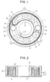
- Fig. 1 is a top plan view of a rotary connector according to an embodiment of the present invention
- Fig. 2 is a sectional view of the rotary connector
- Fig. 3 is a schematic representation illustrative of an essential section of the rotary connector.
- the rotary connector according to the embodiment is constituted mainly by: a fixed housing 1; a movable housing 2 rotatably connected with respect to the fixed housing 1; first and second flat cables 3 and 4 held between the two housings 1 and 2; and a moving member 5 which is disposed between the two housings 1 and 2 such that it may move circularly.
- the fixed housing 1 is constructed by an upper case 6 and a lower case 7 which are combined into one piece; an outer cylindrical section 8 is formed on the lower case 7.
- the movable housing 2 is provided with an inner cylindrical section 9.
- the outer cylindrical section 8 and the inner cylindrical section 9 are coaxially arranged, an annular holding space 10 being formed between the two cylindrical sections 8 and 9.
- Disposed in the holding space 10 is the moving member 5 which is constituted by an annular rotary plate 11 and a plurality of groups of rollers 12 journaled on the rotary plate 11 and a pair of fixed cylinders 13.
- a first opening 14 is formed between one fixed cylinder 13 and one of the rollers 12, and a second opening 15 is formed between the other fixed cylinder 13 and one of the rollers 12, the openings 14 and 15 being located at about 180 degrees opposite from each other.
- W 1 the width of the first opening 14 in the circumferential direction
- W 2 the width of the second opening 15 in the circumferential direction
- the first and second flat cables 3 and 4 are each shaped like a band composed of a plurality of conductors made of copper or the like on one surface of a base film made of an insulating tape of PET or the like.
- the first flat cable 3 is drawn in black
- the second flat cable 4 is drawn in white.
- the outer ends of the two flat cables 3 and 4 are connected to a fixed joint 16 secured to the outer cylindrical section 8 and electrically led out of the fixed housing 1 via the fixed joint 16.
- the inner ends of the two flat cables 3 and 4 are connected to a movable joint 17 fixed to the inner cylindrical section 9 and electrically led out of the movable housing 2 via the joint 17.
- both flat cables 3 and 4 are housed in the holding space 10 such that they are wound counterclockwise along the inner wall of the outer cylindrical section 8 from the fixed joint 16 with the first flat cable 3 being on the outer side, then they are separated such that the first flat cable 3 passes through the first opening 14 and reversed in U shape by one of the rollers 12 (hereinafter referred to as a "reversal section 3a"), whereas the second flat cable 4 passes through the second opening 15 and reversed in U shape by another one of the rollers 12 (hereinafter referred to as a "reversal section 4a"); they are then wound clockwise on the peripheral surface of the inner cylindrical section 9 with the second flat cable being on the outer side before they reach the joint 17.
- the inner end of the first flat cable 3 is directly wound around the inner cylindrical section 9, whereas the inner end of the second flat cable 4 is wound around the inner cylindrical section 9 via approximately one turn of the first flat cable 3.
- D the diameter of the inner cylindrical section 9 of the movable housing 2
- t the thicknesses of the flat cables 3 and 4
- the winding diameter of the first flat cable 3 becomes D
- the winding diameter of the second flat cable 4 becomes (D + 2t); therefore, the winding diameter of the second flat cable 4 wound around the inner cylindrical section 9 is larger than that of that of the first flat cable 3 wound around the inner cylindrical section 9.
- Widths W 1 and W 2 of the first and second openings 14 and 15, respectively, previously described are set with that difference in winding diameter taken into consideration; width W 1 of the first opening 14 through which the reversal section 3a of the first flat cable 3 having the smaller winding diameter passes is set smaller than width W 2 of the second opening 15 through which the reversal section 4a of the second flat cable 4 having the larger winding diameter passes.
- the fixed housing 1 is secured to a stator member of a steering unit, and an external connector, not shown, on a car body is connected to the fixed joint 16.
- the movable housing 2 is fixed to a steering wheel which is the rotor member of the steering unit; an external connector, not shown, on the steering wheel is connected to the movable joint 17.
- the torque is transmitted to the movable housing 2, causing the movable housing 2 to rotate clockwise or counterclockwise.
- the reversal sections 3a and 4a of the first and second flat cables 3 and 4, respectively accordingly move counterclockwise by the amount of rotation which is smaller than that of the movable housing 2, and the moving member 5 also moves counterclockwise in response to the movement of the reversal sections 3a and 4a.
- the flat cables 3 and 4 are unwound from the inner cylindrical section 9 by a length approximately double the movements and wound back onto the outer cylindrical section 8.
- the reversal section 4a of the second flat cable 4 which has a larger winding diameter moves faster than the reversal section 3a of the first flat cable 3 which has a smaller winding diameter; however, since there is the established relationship of W 1 ⁇ W 2 , the two reversal sections 3a and 4a push the fixed cylinders 13 which are respectively located at one end of each of the openings 14 and 15, enabling the moving member 5 to smoothly move in the holding space 10 by being subjected to the forces applied by the two reversal sections 3a and 4a.
- the reversal sections 3a and 4a of the first and second flat cables 3 and 4, respectively accordingly move clockwise by the amount of rotation which is smaller than that of the movable housing 2, and the moving member 5 also moves clockwise in response to the movement of the reversal sections 3a and 4a.
- the flat cables 3 and 4 are unwound from the outer cylindrical section 8 by a length approximately double the movements and tightened by the inner cylindrical section 9.
- the reversal section 4a of the second flat cable 4 which has a larger winding diameter moves faster than the reversal section 3a of the first flat cable 3 which has a smaller winding diameter; however, since there is the established relationship of W 1 ⁇ W 2 , the two reversal sections 3a and 4a pull the rollers 12 which are respectively located at the other ends of the openings 14 and 15, enabling the moving member 5 to smoothly move in the holding space 10 by being subjected to the forces applied by the two reversal sections 3a and 4a.
- widths W 1 and W 2 of the first and second openings 14 and 15 through which the reversal sections 3a and 4a of the flat cables 3 and 4 respectively pass are set to different values according to the difference in the winding diameters of the two flat cables 3 and 4 wound around the inner cylindrical section 9; therefore, when the movable housing 2 rotates, the moving member 5 is rotationally driven primarily by the reversal section 4a of the flat cable 4 having the larger winding diameter, however, the reversal section 3a of the flat cable 3 can be brought in contact with the end of the first opening 14, so that the forces from the reversal sections 3a and 4a of the flat cables 3 and 4, respectively, can be applied to the moving member 5 so as to smoothly move the moving member especially because the first and second openings 14 and 15 are formed at the 180 degrees opposed positions on the moving member 5.
- the inner ends of the flat cables 3 and 4 are bundled at the same location by the movable joint 17, thus allowing the structure of the connection with the external connector on the
- the present invention provides the following advantages.
- the forces from the reversal sections of the flat cables can be uniformly applied to the moving member.
- connection to an external connector can be simplified by providing the inner cylindrical section with a joint for bundling one end of each of the flat cables at the same location and by leading the ends of the flat cables out of the second housing.
Landscapes
- Engineering & Computer Science (AREA)
- Mechanical Engineering (AREA)
- Electric Cable Arrangement Between Relatively Moving Parts (AREA)
- Steering Controls (AREA)
- Storing, Repeated Paying-Out, And Re-Storing Of Elongated Articles (AREA)
Description
- The present invention relates to a rotary connector. Such connector may be incorporated in an automotive steering unit and used as an electrical connection means for an air bag system or the like. More particularly, it relates to a rotary connector in which flat cables are wound in the reverse direction via reversal sections in a holding space formed between a fixed housing and a movable housing. A connector of the above type is from EP-A-0695000.
- A rotary connector has a flat cable which is coiled and placed between a fixed housing and a movable housing which is rotatably mounted with respect to the fixed housing; it is incorporated in an automotive steering unit and employed as an electrical connection means for an air bag inflator or the like attached to a steering wheel which has a finite number of revolutions. The flat cable is shaped like a band and has a plurality of conductors. The rotary connector is known to come in two types; in one type, the flat cable is wound in a coil, and in the other type, the flat cable is reversed in the opposite direction at the middle thereof. In the latter reversal type, the required length of the flat cable can be significantly reduced.
- Such a reversal type rotary connector normally uses one flat cable. As the number of conductors is increased with increasing trend toward multiple-circuit designs, the width of the flat cable inevitably increases as it includes more conductors, preventing the entire rotary connector from being made thinner. To solve the problem, the rotary connector disclosed in the specification of USP No. 3,763,455 supports multiple circuits by employing two flat cables to accommodate the conductors.
- Fig. 4 is a top plan view illustrative of a schematic configuration of a cable reel disclosed in the foregoing patent specification, similar to that of EP-A-0695000. As shown in the drawing, a
movable housing 101 which has a cylindrical inner section is rotatably connected with respect to afixed housing 100 which has a cylindrical outer section; a firstflat cable 103 and a secondflat cable 104 are housed in anannular holding space 102 formed between thefixed housing 100 and themovable housing 101. Theseflat cables holding space 102 so that they are wound around the outer cylindrical section of thefixed housing 100 and the inner cylindrical section of themovable housing 101, the winding directions thereof being opposite from each other. At the position where the winding direction is reversed, U-shapedreversal sections flat cables cable outlet sections movable housing 101 and led out of themovable housing 101 via thecable outlet sections flat cables cable outlet sections fixed housing 100 and led out of thefixed housing 100 via thecable outlet sections holding space 102 are a plurality of groups ofrollers reversal section 103a of the firstflat cable 103 being looped by a group of therollers 105, whereas areversal section 104a of the secondflat cable 104 being looped by a group of therollers 106. - In the rotary connector thus configured, when, for example, the
movable housing 101 is turned clockwise in Fig. 4, thereversal sections flat cables holding space 102 by the amount of turn which is smaller than that of themovable housing 101, causing theflat cables movable housing 101. Conversely, when themovable housing 101 is turned counterclockwise in Fig. 4, thereversal sections flat cables movable housing 101, causing theflat cables fixed housing 100. At the time of such winding up and unwinding, therollers reversal sections flat cables - In the conventional rotary connector described above, the radial deformation of the two
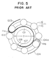
flat cables rollers flat cables holding space 102; however, since the plurality of groups of therollers holding space 102 so that they are separated and independent from each other, vibration applied to the rotary connector causes the groups of therollers - There is a conceivable solution to the problem described above as shown in Fig. 5 wherein, instead of employing the mutually separated and independent groups of the
rollers member 111 which has at least two openings 111a and 111b is disposed in theholding space 102 such that it may circularly move, and thereversal sections flat cables member 111 is composed of a ring-like rotary plate 112 and a plurality of groups of rollers 113 journaled on the rotary plate 112; the openings 111a and 111b are formed at equal intervals between the groups of the rollers 113. Hence, when the movingmember 111 which has such openings 111a and 111b is employed, the rotary plate 112 and the group of the rollers 113 can be handled as one piece and the bumping between the groups of the rollers 113 can be prevented, thus solving the problems with the conventional rotary connector described above; however, it poses a different problem set forth below. - Is the rotary connector, when the diameter of the inner cylindrical section of the
movable housing 101 is denoted as D and the thicknesses of theflat cables flat cable 103 directly wound on the inner cylindrical section becomes D, whereas the winding diameter of the secondflat cable 104 wound on the inner cylindrical section via the firstflat cable 103 which corresponds to approximately one turn becomes (D + 2t); therefore, the winding diameters of the twoflat cables movable housing 101 is turned, the amount of winding of theflat cable 103 onto the inner cylindrical section becomes different from that of theflat cable 104, or the amounts of unwinding of the two flat cables therefrom become different, causing thereversal section 104a of the secondflat cable 104 which has the larger winding diameter to move faster than thereversal section 103a of the firstflat cable 103 which has the smaller winding diameter. As a result, as shown, for example, in the drawing, when theflat cables reversal section 104a of the secondflat cable 104 comes in contact with the roller 113 located at the end of the opening 111b, whereas thereversal section 103a of the firstflat cable 103 moving slower merely moves in the opening 111a and does not come in contact with the roller 113, thus presenting a problem in that the movingmember 111 cannot be smoothly moved by the forces applied by the tworeversal sections - The present invention relates to a rotary connector wherein a moving member disposed in a holding space is provided with a plurality of openings through which the reversal sections of a plurality of flat cables pass, and the width of at least one of the openings in the circumferential direction is set so that it is smaller than others. Thus, instead of setting all the openings of the moving member to the same width, the opening corresponding to the reversal section of the flat cable which has a smaller winding diameter is set smaller than that of the opening corresponding to the reversal section of the flat cable which has a larger diameter so as to enable the moving member to smoothly move in the holding space because the forces of the reversal sections of the flat cables can be respectively applied to the moving member.
- According to the present invention, there is provided a rotary connector having the features of claim 1.
- The moving member functions to prevent the flat cables from deforming in the radial direction in the holding space. The moving member may be constructed, for example, by a plurality of roller groups journaled on a rotary plate; in this case, an opening is formed between a pair of rollers. Some of the rollers may be replaced by a fixed cylinder and an opening may be formed between the fixed cylinder and the rollers.
- If there are an N number of flat cables, then it is necessary to provide the moving member with the N number of openings. Forming the openings at approximately equal intervals in the circumferential direction of the moving member, i.e. locating the openings at approximately 360/N degrees, enables the forces by the reversal sections of the flat cables to be evenly applied to the moving member.
- Providing the inner cylindrical section with a joint for bundling one end of each of the flat cables at a single location and leading one end of each of the flat cables out of the second housing through the joint makes it possible to simplify the structure of the connection with an external connector.
-
- Fig. 1 is a top plan view of a rotary connector in accordance with an embodiment of the present invention;
- Fig. 2 is a sectional view of the rotary connector;
- Fig. 3 is a schematic representation illustrative of an essential section of the rotary connector;
- Fig. 4 is a top plan view of a rotary connector according to a prior art; and
- Fig. 5 a schematic representation of a rotary connector according to another prior art.
- An embodiment of the present invention will be described with reference to the accompanying drawings. Fig. 1 is a top plan view of a rotary connector according to an embodiment of the present invention; Fig. 2 is a sectional view of the rotary connector; and Fig. 3 is a schematic representation illustrative of an essential section of the rotary connector. As shown in these drawings, the rotary connector according to the embodiment is constituted mainly by: a fixed housing 1; a
movable housing 2 rotatably connected with respect to the fixed housing 1; first and secondflat cables housings 1 and 2; and a movingmember 5 which is disposed between the twohousings 1 and 2 such that it may move circularly. - The fixed housing 1 is constructed by an upper case 6 and a lower case 7 which are combined into one piece; an outer
cylindrical section 8 is formed on the lower case 7. Themovable housing 2 is provided with an inner cylindrical section 9. The outercylindrical section 8 and the inner cylindrical section 9 are coaxially arranged, anannular holding space 10 being formed between the twocylindrical sections 8 and 9. Disposed in theholding space 10 is the movingmember 5 which is constituted by an annular rotary plate 11 and a plurality of groups ofrollers 12 journaled on the rotary plate 11 and a pair of fixedcylinders 13. Afirst opening 14 is formed between one fixedcylinder 13 and one of therollers 12, and asecond opening 15 is formed between the other fixedcylinder 13 and one of therollers 12, theopenings first opening 14 in the circumferential direction is denoted as W1 and the width of thesecond opening 15 in the circumferential direction is denoted as W2, these widths are set to have a relationship of W1 < W2. - The first and second
flat cables flat cable 3 is drawn in black, whereas the secondflat cable 4 is drawn in white. The outer ends of the twoflat cables fixed joint 16 secured to the outercylindrical section 8 and electrically led out of the fixed housing 1 via thefixed joint 16. The inner ends of the twoflat cables movable joint 17 fixed to the inner cylindrical section 9 and electrically led out of themovable housing 2 via thejoint 17. At this time, bothflat cables space 10 such that they are wound counterclockwise along the inner wall of the outercylindrical section 8 from the fixed joint 16 with the firstflat cable 3 being on the outer side, then they are separated such that the firstflat cable 3 passes through thefirst opening 14 and reversed in U shape by one of the rollers 12 (hereinafter referred to as a "reversal section 3a"), whereas the secondflat cable 4 passes through thesecond opening 15 and reversed in U shape by another one of the rollers 12 (hereinafter referred to as a "reversal section 4a"); they are then wound clockwise on the peripheral surface of the inner cylindrical section 9 with the second flat cable being on the outer side before they reach the joint 17. - Hence, the inner end of the first
flat cable 3 is directly wound around the inner cylindrical section 9, whereas the inner end of the secondflat cable 4 is wound around the inner cylindrical section 9 via approximately one turn of the firstflat cable 3. More specifically, if the diameter of the inner cylindrical section 9 of themovable housing 2 is denoted as D and the thicknesses of theflat cables flat cable 3 becomes D, while the winding diameter of the secondflat cable 4 becomes (D + 2t); therefore, the winding diameter of the secondflat cable 4 wound around the inner cylindrical section 9 is larger than that of that of the firstflat cable 3 wound around the inner cylindrical section 9. Widths W1 and W2 of the first andsecond openings first opening 14 through which thereversal section 3a of the firstflat cable 3 having the smaller winding diameter passes is set smaller than width W2 of thesecond opening 15 through which thereversal section 4a of the secondflat cable 4 having the larger winding diameter passes. - The operation of the rotary connector according to the embodiment will now be described. In this embodiment, the fixed housing 1 is secured to a stator member of a steering unit, and an external connector, not shown, on a car body is connected to the fixed joint 16. The
movable housing 2 is fixed to a steering wheel which is the rotor member of the steering unit; an external connector, not shown, on the steering wheel is connected to the movable joint 17. - In operation, when the steering wheel is turned clockwise or counterclockwise, the torque is transmitted to the
movable housing 2, causing themovable housing 2 to rotate clockwise or counterclockwise. For instance, when themovable housing 2 rotates counterclockwise from the neutral position of the steering wheel, thereversal sections flat cables movable housing 2, and the movingmember 5 also moves counterclockwise in response to the movement of thereversal sections flat cables cylindrical section 8. In this case, thereversal section 4a of the secondflat cable 4 which has a larger winding diameter moves faster than thereversal section 3a of the firstflat cable 3 which has a smaller winding diameter; however, since there is the established relationship of W1 < W2, the tworeversal sections cylinders 13 which are respectively located at one end of each of theopenings member 5 to smoothly move in the holdingspace 10 by being subjected to the forces applied by the tworeversal sections - Conversely, when the
movable housing 2 rotates clockwise from a state where the steering wheel is in the neutral position, thereversal sections flat cables movable housing 2, and the movingmember 5 also moves clockwise in response to the movement of thereversal sections flat cables cylindrical section 8 by a length approximately double the movements and tightened by the inner cylindrical section 9. In this case, thereversal section 4a of the secondflat cable 4 which has a larger winding diameter moves faster than thereversal section 3a of the firstflat cable 3 which has a smaller winding diameter; however, since there is the established relationship of W1 < W2, the tworeversal sections rollers 12 which are respectively located at the other ends of theopenings member 5 to smoothly move in the holdingspace 10 by being subjected to the forces applied by the tworeversal sections - Thus, in the embodiment described above, widths W1 and W2 of the first and
second openings reversal sections flat cables flat cables movable housing 2 rotates, the movingmember 5 is rotationally driven primarily by thereversal section 4a of theflat cable 4 having the larger winding diameter, however, thereversal section 3a of theflat cable 3 can be brought in contact with the end of thefirst opening 14, so that the forces from thereversal sections flat cables member 5 so as to smoothly move the moving member especially because the first andsecond openings member 5. In addition, the inner ends of theflat cables - In the above embodiment, the description has been given to the case there two flat cables are employed; however, the present invention can also be applied to a case where three or more flat cables are used. In that case, three or more flat cables are used, the widths of a plurality of openings through which the reversal sections of the flat cables pass are to be properly set according to the differences among the winding diameters of the flat cables wound around the inner cylindrical section.
- Thus, the present invention provides the following advantages.
- By providing a moving member disposed in a holding space with a plurality of openings through which the reversal sections of a plurality of flat cables pass, and by setting the width of at least one of the openings in the circumferential direction so that it is smaller than others, even if the reversal sections of the flat cables move at different speeds due to the different winding diameters when winding up or unwinding the flat cables, the forces from these reversal sections can be respectively applied to the moving member so as to smoothly move the moving member.
- Further, by forming the openings at about equal intervals in the circumferential direction of the moving member, the forces from the reversal sections of the flat cables can be uniformly applied to the moving member.
- Furthermore, the structure of the connection to an external connector can be simplified by providing the inner cylindrical section with a joint for bundling one end of each of the flat cables at the same location and by leading the ends of the flat cables out of the second housing.
Claims (9)
- A rotary connector comprising:a first housing (1) which has an outer cylindrical section(8); a second housing (2) which is rotatably attached to said first housing (1) and which has an inner cylindrical section (9) opposed to said outer cylindrical section (8) via an annular holding space (10); a plurality of flat cables which are wound in said holding space (10) such that the winding directions thereof are reversed in the middle and both ends thereof are respectively fixed to said outer cylindrical section (8) and said inner cylindrical section (9); and a moving member (5) which is disposed in said holding space so that it may circularly move and which has a plurality of openings (14, 15) through which the reversal sections (3a, 4a) of said flat cables pass (3,4) ; charaterized in thatthe width (W1) of at least one of said openings (14,15) in the circumferential direction is set so that it is smaller than those (W2) of others.
- A rotary connector according to Claim 1, wherein said openings (14,15) are provided at approximately equal intervals in the circumferential direction of said moving member(5).
- A rotary connector according to Claim 1 or 2, wherein said inner cylindrical section (9) is provided with a joint (17) for bundling one end of each of said flat cables (3,4) at a single location.
- A rotary connector according to Claim 1 or 2, wherein said outer cylindrical section (8) is provided with a joint (16) for bundling one end of each of said flat cables (3,4) at a single location.
- A rotary connector according to any of Claims 1 to 4, wherein at least one of said plurality of openings has a roller (12) on which said flat cable (3,4) is reversed and a fixed cylinder (13) opposed to said roller (12) via said flat cable 3,4.
- A rotary connector according to any of claims 1 to 5, wherein
two flat cables(3,4) which are wound in said holding space (10) such that the winding directions thereof are reversed in the middle and both ends thereof are respectively fixed to said outer cylindrical sections (8) and said inner cylindrical section (9); said moving member (5) having two openings through which the reversal sections (3a,4a) of said flat cables (3,4) pass; and wherein
the width (W1) of one of said two openings in the circumferential direction is set so that it is smaller than (W2) that of the other (15). - A rotary connector according to Claim 6, wherein said two openings are provided at positions 180 degrees opposed to each other in said moving member (5).
- A rotary connector according to Claim 6 or 7, wherein said inner cylindrical section is provided with a joint for bundling one end of each of said flat cables at a single location.
- A rotary connector according to any of claims 6 to 8 wherein at outer cylindrical section is provided with a joint for bundling one end of each of said flat cables at a single location.
Applications Claiming Priority (3)
| Application Number | Priority Date | Filing Date | Title |
|---|---|---|---|
| JP18499696 | 1996-07-15 | ||
| JP184996/96 | 1996-07-15 | ||
| JP18499696 | 1996-07-15 |
Publications (3)
| Publication Number | Publication Date |
|---|---|
| EP0820125A2 EP0820125A2 (en) | 1998-01-21 |
| EP0820125A3 EP0820125A3 (en) | 1999-09-22 |
| EP0820125B1 true EP0820125B1 (en) | 2006-09-13 |
Family
ID=16162966
Family Applications (1)
| Application Number | Title | Priority Date | Filing Date |
|---|---|---|---|
| EP97111960A Expired - Lifetime EP0820125B1 (en) | 1996-07-15 | 1997-07-14 | Rotary connector |
Country Status (4)
| Country | Link |
|---|---|
| US (1) | US5882216A (en) |
| EP (1) | EP0820125B1 (en) |
| KR (1) | KR100240094B1 (en) |
| DE (1) | DE69736648T2 (en) |
Families Citing this family (19)
| Publication number | Priority date | Publication date | Assignee | Title |
|---|---|---|---|---|
| US6213797B1 (en) * | 1994-07-19 | 2001-04-10 | Methode Electronics, Inc. | Clockspring having non-compliant and compliant roller members |
| JP3408949B2 (en) * | 1997-06-09 | 2003-05-19 | アルプス電気株式会社 | Rotating connector |
| GB2328330B (en) * | 1997-07-10 | 2002-10-30 | Alps Electric Co Ltd | Rotatable connector |
| DE19882022B4 (en) * | 1997-11-28 | 2010-05-06 | Furukawa Electric Co., Ltd., | Use of a rotary connector in a vehicle steering device |
| JP3518673B2 (en) | 1999-06-23 | 2004-04-12 | アルプス電気株式会社 | In-vehicle rotary connector |
| JP4716541B2 (en) * | 2000-04-14 | 2011-07-06 | ナイルス株式会社 | Rotating connector device |
| JP2002034139A (en) | 2000-07-17 | 2002-01-31 | Auto Network Gijutsu Kenkyusho:Kk | Rotary connection device |
| EP1247697A3 (en) | 2001-04-03 | 2003-10-22 | Tyco Electronics AMP GmbH | Rotary loop back connector |
| JP2003197339A (en) * | 2001-12-26 | 2003-07-11 | Furukawa Electric Co Ltd:The | Rotary connector |
| US6962497B2 (en) * | 2003-04-16 | 2005-11-08 | The Furukawa Electric Co., Ltd. | Rotary connector having an identifiable neutral position |
| WO2006037109A2 (en) * | 2004-09-27 | 2006-04-06 | Deka Products Limited Partnership | Infusion set improvements |
| JP4602176B2 (en) * | 2005-07-01 | 2010-12-22 | 矢崎総業株式会社 | Rotating connector device |
| JP4448882B2 (en) * | 2008-01-08 | 2010-04-14 | アルプス電気株式会社 | Rotating connector |
| US7758364B1 (en) * | 2009-08-04 | 2010-07-20 | Seagate Technology Llc | Rotary positioning |
| JP6066543B2 (en) | 2010-11-24 | 2017-01-25 | 矢崎総業株式会社 | Flat harness winding device |
| JP5624972B2 (en) * | 2011-10-31 | 2014-11-12 | 古河電気工業株式会社 | Rotating connector device |
| JP5890258B2 (en) * | 2012-06-11 | 2016-03-22 | 矢崎総業株式会社 | Rotating connector |
| JP6487224B2 (en) * | 2014-05-01 | 2019-03-20 | アルプスアルパイン株式会社 | Rotating connector |
| US11495930B2 (en) * | 2021-02-05 | 2022-11-08 | American Furukawa, Inc. | Auto-lock assembly |
Family Cites Families (4)
| Publication number | Priority date | Publication date | Assignee | Title |
|---|---|---|---|---|
| US3763455A (en) * | 1971-12-17 | 1973-10-02 | Gen Motors Corp | Electrically coupled steering column |
| JP3050688B2 (en) * | 1992-02-20 | 2000-06-12 | 古河電気工業株式会社 | Transmission device between rotating body and fixed body |
| JP2540938Y2 (en) * | 1992-09-04 | 1997-07-09 | 古河電気工業株式会社 | Transmission device between rotating body and fixed body |
| TW317043B (en) * | 1994-07-19 | 1997-10-01 | Methode Electronics Inc |
-
1997
- 1997-07-08 US US08/889,679 patent/US5882216A/en not_active Expired - Lifetime
- 1997-07-14 DE DE69736648T patent/DE69736648T2/en not_active Expired - Lifetime
- 1997-07-14 EP EP97111960A patent/EP0820125B1/en not_active Expired - Lifetime
- 1997-07-15 KR KR1019970032823A patent/KR100240094B1/en not_active Expired - Lifetime
Also Published As
| Publication number | Publication date |
|---|---|
| US5882216A (en) | 1999-03-16 |
| KR980012733A (en) | 1998-04-30 |
| KR100240094B1 (en) | 2000-01-15 |
| DE69736648T2 (en) | 2007-09-13 |
| MX9705329A (en) | 1998-08-30 |
| DE69736648D1 (en) | 2006-10-26 |
| EP0820125A3 (en) | 1999-09-22 |
| EP0820125A2 (en) | 1998-01-21 |
Similar Documents
| Publication | Publication Date | Title |
|---|---|---|
| EP0820125B1 (en) | Rotary connector | |
| JP3050688B2 (en) | Transmission device between rotating body and fixed body | |
| US5890921A (en) | Rotary connector | |
| JP2752529B2 (en) | Cable reel | |
| JPH0321544A (en) | Wiring device | |
| EP1063132B1 (en) | Rotary connector | |
| JP2540916Y2 (en) | Transmission device between two members that rotate relatively | |
| JPH06338371A (en) | Cable reel | |
| US6302716B1 (en) | Rotatable connector | |
| JPH08227775A (en) | Rotary connector | |
| US5690500A (en) | Electrical connecting device for connecting rotor with stator through cable | |
| JPH113762A (en) | Rotary connector | |
| JP3037784B2 (en) | Cable reel | |
| JP3518655B2 (en) | Rotating connector | |
| JP2000150098A (en) | Rotating connector | |
| JP2774724B2 (en) | Cable reel | |
| JP3717309B2 (en) | Rotating connector | |
| MXPA97005329A (en) | Rotary connector | |
| JP2999584B2 (en) | Cable reel | |
| JP2702626B2 (en) | Cable reel | |
| JP3518659B2 (en) | Rotating connector | |
| JP2999593B2 (en) | Cable reel | |
| JP3374113B2 (en) | Transmission device between rotating body and fixed body | |
| JPH113761A (en) | Rotary connector | |
| JP3408941B2 (en) | Rotating connector |
Legal Events
| Date | Code | Title | Description |
|---|---|---|---|
| PUAI | Public reference made under article 153(3) epc to a published international application that has entered the european phase |
Free format text: ORIGINAL CODE: 0009012 |
|
| AK | Designated contracting states |
Kind code of ref document: A2 Designated state(s): DE GB IE SE |
|
| PUAL | Search report despatched |
Free format text: ORIGINAL CODE: 0009013 |
|
| AK | Designated contracting states |
Kind code of ref document: A3 Designated state(s): AT BE CH DE DK ES FI FR GB GR IE IT LI LU MC NL PT SE |
|
| RIC1 | Information provided on ipc code assigned before grant |
Free format text: 6H 01R 35/04 A, 6H 01R 35/02 B |
|
| 17P | Request for examination filed |
Effective date: 19991012 |
|
| AKX | Designation fees paid |
Free format text: DE GB IE SE |
|
| GRAP | Despatch of communication of intention to grant a patent |
Free format text: ORIGINAL CODE: EPIDOSNIGR1 |
|
| GRAS | Grant fee paid |
Free format text: ORIGINAL CODE: EPIDOSNIGR3 |
|
| GRAA | (expected) grant |
Free format text: ORIGINAL CODE: 0009210 |
|
| AK | Designated contracting states |
Kind code of ref document: B1 Designated state(s): DE GB IE SE |
|
| REG | Reference to a national code |
Ref country code: GB Ref legal event code: FG4D |
|
| REG | Reference to a national code |
Ref country code: IE Ref legal event code: FG4D |
|
| REF | Corresponds to: |
Ref document number: 69736648 Country of ref document: DE Date of ref document: 20061026 Kind code of ref document: P |
|
| REG | Reference to a national code |
Ref country code: SE Ref legal event code: TRGR |
|
| PLBE | No opposition filed within time limit |
Free format text: ORIGINAL CODE: 0009261 |
|
| STAA | Information on the status of an ep patent application or granted ep patent |
Free format text: STATUS: NO OPPOSITION FILED WITHIN TIME LIMIT |
|
| 26N | No opposition filed |
Effective date: 20070614 |
|
| PG25 | Lapsed in a contracting state [announced via postgrant information from national office to epo] |
Ref country code: IE Free format text: LAPSE BECAUSE OF NON-PAYMENT OF DUE FEES Effective date: 20070716 |
|
| PGFP | Annual fee paid to national office [announced via postgrant information from national office to epo] |
Ref country code: SE Payment date: 20080724 Year of fee payment: 12 |
|
| EUG | Se: european patent has lapsed | ||
| PG25 | Lapsed in a contracting state [announced via postgrant information from national office to epo] |
Ref country code: SE Free format text: LAPSE BECAUSE OF NON-PAYMENT OF DUE FEES Effective date: 20090715 |
|
| PGFP | Annual fee paid to national office [announced via postgrant information from national office to epo] |
Ref country code: GB Payment date: 20160624 Year of fee payment: 20 |
|
| PGFP | Annual fee paid to national office [announced via postgrant information from national office to epo] |
Ref country code: DE Payment date: 20160801 Year of fee payment: 20 |
|
| REG | Reference to a national code |
Ref country code: DE Ref legal event code: R082 Ref document number: 69736648 Country of ref document: DE Representative=s name: SCHMITT-NILSON SCHRAUD WAIBEL WOHLFROM PATENTA, DE |
|
| REG | Reference to a national code |
Ref country code: DE Ref legal event code: R071 Ref document number: 69736648 Country of ref document: DE |
|
| REG | Reference to a national code |
Ref country code: GB Ref legal event code: PE20 Expiry date: 20170713 |
|
| PG25 | Lapsed in a contracting state [announced via postgrant information from national office to epo] |
Ref country code: GB Free format text: LAPSE BECAUSE OF EXPIRATION OF PROTECTION Effective date: 20170713 |