EP0819936A1 - Ein verbesserter temperaturausgegliechener elektrochemischer Sensor und Verfahren zur genauen Überwachung von Temperaturänderungen eines zu untersuchenden Gases - Google Patents
Ein verbesserter temperaturausgegliechener elektrochemischer Sensor und Verfahren zur genauen Überwachung von Temperaturänderungen eines zu untersuchenden Gases Download PDFInfo
- Publication number
- EP0819936A1 EP0819936A1 EP97305025A EP97305025A EP0819936A1 EP 0819936 A1 EP0819936 A1 EP 0819936A1 EP 97305025 A EP97305025 A EP 97305025A EP 97305025 A EP97305025 A EP 97305025A EP 0819936 A1 EP0819936 A1 EP 0819936A1
- Authority
- EP
- European Patent Office
- Prior art keywords
- gas
- temperature
- sensor
- gas sensor
- thermistor
- Prior art date
- Legal status (The legal status is an assumption and is not a legal conclusion. Google has not performed a legal analysis and makes no representation as to the accuracy of the status listed.)
- Granted
Links
Images


Classifications
-
- G—PHYSICS
- G01—MEASURING; TESTING
- G01N—INVESTIGATING OR ANALYSING MATERIALS BY DETERMINING THEIR CHEMICAL OR PHYSICAL PROPERTIES
- G01N27/00—Investigating or analysing materials by the use of electric, electrochemical, or magnetic means
- G01N27/26—Investigating or analysing materials by the use of electric, electrochemical, or magnetic means by investigating electrochemical variables; by using electrolysis or electrophoresis
- G01N27/403—Cells and electrode assemblies
- G01N27/404—Cells with anode, cathode and cell electrolyte on the same side of a permeable membrane which separates them from the sample fluid, e.g. Clark-type oxygen sensors
-
- G—PHYSICS
- G01—MEASURING; TESTING
- G01N—INVESTIGATING OR ANALYSING MATERIALS BY DETERMINING THEIR CHEMICAL OR PHYSICAL PROPERTIES
- G01N27/00—Investigating or analysing materials by the use of electric, electrochemical, or magnetic means
- G01N27/02—Investigating or analysing materials by the use of electric, electrochemical, or magnetic means by investigating impedance
- G01N27/04—Investigating or analysing materials by the use of electric, electrochemical, or magnetic means by investigating impedance by investigating resistance
- G01N27/14—Investigating or analysing materials by the use of electric, electrochemical, or magnetic means by investigating impedance by investigating resistance of an electrically-heated body in dependence upon change of temperature
Definitions
- This invention relates to electrochemical gas sensors for electrically signalling the concentration of an electrochemically active gas, such as oxygen, in a gas mixture and more part-. icularly to improved apparatus and methods for closely tracking temperature variations of the gases applied to the gas sensor permitting accurate compensation for the temperature variations.
- an electrochemically active gas such as oxygen
- Electrochemical gas sensors are well known in the prior art for accurately detecting the concentration of an electrochemically active gas, such as oxygen, in a gas mixture.
- the concentration of the gas is externally signalled by the electrical signal generated by the presence of the active gas that is oxidized or reduced at the surface of the gas sensing cathode electrode.
- the gas sensors comprise anode and cathode electrodes immersed in a pool of a liquid electrolyte.
- the electrical output signal from these gas sensors are in the form of an electrical current that corresponds to the partial pressure of the active gas being sensed.
- the current signal can be converted to a voltage signal by the mounting of a suitable resistor across the output terminals of the gas sensor to derive a voltage signal in millivolts.
- a printed circuit board is mounted to the gas sensor at the back side thereof with a suitable resistor thereon for providing the voltage output signal.
- the gas sensor output signals are dependent on the temperature of the gas mixture applied thereto.
- the output signals from the sensors increase with an increase in the temperature of the applied gases. This change in output signal is due to the change in the diffusion rate of the gas mixture through the input membrane for the gas sensor.
- the electrical output signal increases due to the high diffusion rate of the gases through the input membrane for the gas sensor. As a result, the output signal increase results in an erroneous output signal of the concentration of the gas sensed.
- a suitable thermistor is conventionally mounted on the printed circuit board on the rear of the gas sensor.
- the thermistor provides an electrical output signal for adjusting or compensating the sensor output signal for the temperature variations in the applied gas. This enables the gas sensor to provide accurate measurements of the concentrations of the sensed active gas at various temperatures without any additional correction being required.
- These gas sensors have a sensing membrane at the front side for receiving the gas mixture to be analyzed. A pool of electrolyte is stored between the input sensing membrane and an expansion membrane. The thermistor is spaced from the electrolyte.
- This prior art arrangement of the thermistor in gas sensors has been found to take a long time to equilibrate the changes in temperature of the gas mixture applied to the sensor in order to provide a temperature compensation signal.
- the thermistor in these prior art sensor arrangements is exposed to the gas indergoing analysis immediately upon application of the gas mixture to the sensor, while it takes 30-40 minutes for the sensor body to see a change in the temperature of the applied gas mixture. As a result of this time delay there is an initial low reading due to the adjustment performed by the thermistor. This time delay may be on the order of 30 minutes to one hour.
- the present invention is an improved, more sensitive, electrochemical gas sensor having improved methods and means for tracking the temperature changes in the gases applied to the sensors for permitting the temperature compensation signals to be rapidly developed and utilized without any time delay, for providing correct, temperature compensated output signals and thereby accurate electrical output signals representative of the concentrations of the electrochemical active gases applied to the gas sensor to be analyzed.
- the above advantages are produced with small change in the cost of producing the improved gas sensor.
- the improved electrochemical gas sensor includes thermistor means mounted adjacent to an expansion membrane, that is in contact with the gas sensor electrolyte and contains same, in a substantially thermal isolated relationship with respect to the temperature of the gases to be sensed conveyed to the gas sensor so that any change in the temperature of the gas to be sensed is not directly conveyed to the thermistor means whereby the gas sensor and the thermistor means both experience any change in temperature of the gas to be sensed at substantially the same time whereby said thermistor means provides electrical output signals in response to the sensed temperature changes in the gases being sensed without any substantial time delays between the temperature changes in the gases to be sensed and the electrical output signals provided by the thermistor means.
- the present invention comprehends the provision of an electrochemical gas sensor to provide an electrical output signal in response to the application of a gas mixture to the gas sensor having an electo-chemically active gas to be sensed therein due to the production of a cathodic reaction whereby the electrical output signal is representative of the concentration of the sensed electrochemically active gas that varies with the temperatures of the gas mixtures thereby resulting in erroneous electrical output signals due to the temperature variations of the gas mixture, mounting thermistor means in the gas sensor in a preselected thermal insulative manner for minimizing any direct heat transfer to the thermistor means so that the gas sensor body and the thermistor means are exposed to the temperature variations of the gas mixture at essentially the same time for thereby permitting accurate compensation of the electrical output signals from the gas sensor, without any time delay, thereby providing accurate output signals of the concentrations of the sensed gases despite temperature variations in the applied gas mixtures.
- the method includes the steps of mounting the thermistor means in a heat sink adjacent the gas sensor electrolyte and providing a plurality of thermal insulators stacked in the gas sensor with the thermistor means lead wires spiraled into coils and electrically accessible outside the gas sensor.
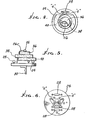
- the electrochemical gas sensor 10 is illustrated in Fig. 1 as a prior art galvanic type of gas sensor for producing a cathodic reaction at the gas sensing cathode electrode 12 for the gas sensor.
- the cathodic reaction is produced in response to gas mixtures applied to the gas sensor 10 when the cathode electrode 12 and the associated anode electrode 14 are wet by a suitable electrolyte 16 stored in the container 18 defining the body for the sensor 10.
- the electrolyte 16 has a preselected volume defined between the thin sensing membrane 20 and the expansion membrane 22 spaced on the opposite side of the anode electrode 14 from the cathode electrode 12.
- the back side of the container 18 is closed off by the provision of a printed circuit board 24 illustrated spaced from the membrane 22 and mounting a thermistor 26 and a plurality of resistors 28.
- An electrical connector 30 is connected to the printed circuit board 24 for deriving the electrical output signals produced by the aforementioned cathodic reaction and the thermistor signals to be combined for compensating for any temperature changes in the gas mixture applied to the gas sensor 10 in a well known manner.
- This structure is typical of the prior art galvanic type of electrochemical gas sensors capable of sensing the concentrations of electrochemically active gases, such as oxygen, in the gas mixtures applied to the gas sensor in parts per million. It should be recognized by those skilled in the art that the present invention is also applicable to other types of gas sensors including polarographic type gas sensors.
- the open end of the container 18 is illustrated with an open ended threaded member 32 for receiving the gas mixtures applied to the gas sensor 10.
- a suitable gas block for receiving the gas mixtures flowing through to impinge against the sensing membrane 20.
- a gas block may be constructed of aluminum or plastic.
- the gas block is diagrammatically illustrated in dotted outline secured to the member 32 in Fig. 1.
- the electrical current can be converted to a voltage output signal by the provision of a suitable output resistor coupled across the output terminals of the sensor 10.
- a ten ohm resistor mounted on the printed circuit board 24, for example will convert the output currents to a voltage signal in millivolts.
- electrical output signals from the gas sensors 10 are also dependent on the temperature and the temperature variations of the gas mixtures applied to the sensor. The electrical output signals increase in magnitude with the increases in the temperatures of the gas mixture being sensed or analyzed. This change in output signal is due to the change in the diffusion rate of the applied gas through the thin sensing membrane 20.
- the prior art gas sensors utilized a temperature sensing device in the form of the thermistor 26 mounted on the printed circuit board 24 for the gas sensor 10 to provide an electrical output signal representative of the temperature change in the applied gas to the gas sensor.
- the thermistor output signal is utilized as a temperature compensating signal for the erroneously generated sensor output signal to provide the correct output signal compensated for the temperature variations, as well known, without the need for additional corrections.
- the thermistor signals are utilized to cancel out the temperature components of the sensor generated signals in a known circuit manner.
- the gas mixture to be analyzed is immediately exposed to the thermistor 26 and as a result signals a temperature change that produces an initial low, erroneous output signal from the gas sensor 10.
- the gas sensor body takes a time period on the order of 30-40 minutes to change in temperature before it will correctly signal the temperature change in the applied gas mixture.
- This time delay in providing accurate electrical output signals has been found to be between 30 minutes to one hour. For a patient in a critical care unit wherein the supply of oxygen, for example, is monitored this time delay is excessive and the errors introduced with the delayed temperature tracking by the thermistor could be up to 10% of the required oxygen supply and could be detrimental to a patient.
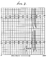
- the time delay introduced by the erroneous temperature tracking by the thermistor 26 for the gas sensor 10 is graphically illustrated in Fig. 2 for a temperature change from 24 degrees centigrade to 40 degrees centrigade for tests conducted on three different gas sensors of the type of gas sensor 10.
- the space between the vertical lines in Fig. 2 represent 5 minutes in time. All three gas sensors signalled an immediate drop in the value of the electrical output signal due to the thermistor 26 being immediately exposed to the temperature change with a gradual increase in value as the sensor body absorbs the temperature change with time.
- the electrical output signal reachesasteady state condition after the time delay period required by the sensor body and associated elements to reach the changed temperature, in the above example the 40 degrees C.
- This time delay period for the cells of Fig. 2 can be seen to be substantial, on the order of 30 minutes.
- the improved gas sensor 10' of the present invention will be examined in conjunction with the structures illustrated in Figs. 3-6 and the graphical representation of Pig. 7.
- the basic structure of the galvanic type electrochemical gas sensor 10 of Fig. 1 is illustrated in Fig. 3 but illustrating the improved arrangement for sensing the applied gas temperatures and tracking the temperatures without introducing the time delays of the prior art structures.
- the thermistor 26 in accordance with the present invention is located in very close proximity to the liquid electrolyte adjacent the expansion membrane 22 in a substantially thermally insulated relationship with the gas sensor body and the gases applied to the gas sensor 10' and thereby eliminates the prior art time delays involved in tracking the temperatures of the gases applied to the gas sensors during a change in the temperature of the gases.
- the thermistor 26 is potted to the rear side of the expansion membrane 22 with a heat sink compound 34, such as a zinc oxide or silicone, as illustrated in Fig. 3.
- a heat sink compound 34 such as a zinc oxide or silicone
- the lead wires for the thermistor 26 comprise an electrically insulated cable 26C of approximately 3-4 inches in length having the individual lead wires thereof secured to the printed circuit board 24 at the points "4" on the board; see Figs. 4 and 6.
- the insulative means comprises three individual layers of foam stacked upon one another between the heat sink 34 and the printed circuit board 24.
- the individual layers of foam insulation are each a different size and are identified in the drawings as layers 36, 38 and 40 from the top to the bottom, see Fig, 5, in particular.
- the top most insulative layer 36 is positioned below the thermistor 26 and the heat sink compound 34 and is the smallest in size, diameter wise, of the three insulative layers.
- the bottom insulative layer 40 is the largest in diameter while the layer 38 is intermediate in size between the diameters of layers 36 and 40.
- the thickness of the three layers are essentially the same and in combination occupy the volume between the heat sink compound 34 and the printed circuit board 24.
- the three layers are arranged in a staggered relationship as best seen in Fig. 5.
- the insulative cable 26C for the thermistor 26 is spiraled or coiled between the insulative layers 36, 38 and 40 between the stacked layers, see Figs. 3 and 4, and the individual lead wires of the cable 26C are connected to point "4" on the printed circuit board 24, as best seen in Fig. 4 and 6.
- the gas sensor 10' was tested in the identical manner as the sensor 10 and plotted in Fig. 7 for a temperature change in the sensor applied gas from 24 degrees C. to 40 degrees C.
- the output signals for six gas sensors are illustrated as coming to equilibrium right away, without any false increases or decreases in electrical output signals as in the known prior art devices.
Landscapes
- Chemical & Material Sciences (AREA)
- Health & Medical Sciences (AREA)
- Life Sciences & Earth Sciences (AREA)
- Analytical Chemistry (AREA)
- Physics & Mathematics (AREA)
- Electrochemistry (AREA)
- Chemical Kinetics & Catalysis (AREA)
- Biochemistry (AREA)
- General Health & Medical Sciences (AREA)
- General Physics & Mathematics (AREA)
- Immunology (AREA)
- Pathology (AREA)
- Molecular Biology (AREA)
- Investigating Or Analyzing Materials By The Use Of Electric Means (AREA)
- Measuring Oxygen Concentration In Cells (AREA)
Applications Claiming Priority (2)
| Application Number | Priority Date | Filing Date | Title |
|---|---|---|---|
| US683985 | 1996-07-19 | ||
| US08/683,985 US5788832A (en) | 1996-07-19 | 1996-07-19 | Temperature compensated electrochemical gas sensor and method for closely tracking the temperature variations of a gas to be sensed |
Publications (2)
| Publication Number | Publication Date |
|---|---|
| EP0819936A1 true EP0819936A1 (de) | 1998-01-21 |
| EP0819936B1 EP0819936B1 (de) | 2003-05-07 |
Family
ID=24746250
Family Applications (1)
| Application Number | Title | Priority Date | Filing Date |
|---|---|---|---|
| EP97305025A Expired - Lifetime EP0819936B1 (de) | 1996-07-19 | 1997-07-09 | Ein temperaturausgegliechener elektrochemischer Sensor und Verfahren zur genauen Überwachung von Temperaturänderungen eines zu untersuchenden Gases |
Country Status (8)
| Country | Link |
|---|---|
| US (1) | US5788832A (de) |
| EP (1) | EP0819936B1 (de) |
| JP (1) | JPH10115600A (de) |
| KR (1) | KR980010414A (de) |
| AR (1) | AR007921A1 (de) |
| CA (1) | CA2209784A1 (de) |
| DE (1) | DE69721653T2 (de) |
| SG (1) | SG66380A1 (de) |
Cited By (2)
| Publication number | Priority date | Publication date | Assignee | Title |
|---|---|---|---|---|
| DE10007396C2 (de) * | 2000-02-18 | 2003-04-10 | It Dr Gambert Gmbh | Vorrichtung zum Abgleich von galvanischen Sensoren |
| EP1555043A2 (de) | 2004-01-14 | 2005-07-20 | Bernhard Engl | Vorrichtung zur Mischgaszufuhr in Kreislaufatemgeräten |
Families Citing this family (9)
| Publication number | Priority date | Publication date | Assignee | Title |
|---|---|---|---|---|
| US6265750B1 (en) | 1999-07-15 | 2001-07-24 | Teledyne Technologies Incorporated | Electrochemical gas sensor and method of making the same |
| KR100497991B1 (ko) * | 2002-07-29 | 2005-07-01 | 세주엔지니어링주식회사 | 휴대용 가스 검출기 및 그의 재기초화 방법 |
| US7140232B2 (en) * | 2002-12-16 | 2006-11-28 | Radiodetection Limited | Method and apparatus for multiple gas sensor |
| US20060203886A1 (en) * | 2005-03-10 | 2006-09-14 | Aai Corporation | Simplified thermal isolator for temperature sensor |
| US7664607B2 (en) | 2005-10-04 | 2010-02-16 | Teledyne Technologies Incorporated | Pre-calibrated gas sensor |
| JP4974304B2 (ja) * | 2007-10-29 | 2012-07-11 | 日本特殊陶業株式会社 | センサ制御装置 |
| JP6126852B2 (ja) | 2012-02-21 | 2017-05-10 | ハウメット コーポレイションHowmet Corporation | ガスタービン部品のコーティング及びコーティング方法 |
| US10175254B2 (en) | 2013-07-16 | 2019-01-08 | Palo Alto Health Sciences, Inc. | Methods and systems for quantitative colorimetric capnometry |
| US11415491B2 (en) * | 2018-09-27 | 2022-08-16 | Apple Inc. | Pumping mechanism for gas sensors |
Citations (5)
| Publication number | Priority date | Publication date | Assignee | Title |
|---|---|---|---|---|
| GB1166683A (en) * | 1965-12-13 | 1969-10-08 | Ceskoslovenska Akademie Ved | Potentiometric Sensing Device for Measuring the Oxygen Content of Liquids |
| US3510421A (en) * | 1967-06-12 | 1970-05-05 | Honeywell Inc | Polarographic cell |
| CH560390A5 (de) * | 1973-03-22 | 1975-03-27 | Radiometer As | |
| EP0113966A2 (de) * | 1983-01-12 | 1984-07-25 | Allied Corporation | Elektrochemische Elektrodevorrichtung |
| EP0122511A2 (de) * | 1983-03-25 | 1984-10-24 | Hitachi, Ltd. | Verfahren und Vorrichtung zur gleichzeitigen Messung der Konzentrationen von aufgelösten Gasen |
Family Cites Families (7)
| Publication number | Priority date | Publication date | Assignee | Title |
|---|---|---|---|---|
| US3351544A (en) * | 1964-03-23 | 1967-11-07 | Honeywell Inc | Gas detecting cell with detachable unit |
| US3767552A (en) * | 1971-10-06 | 1973-10-23 | Teledyne Ind | Gas analyzer |
| DK143246C (da) * | 1978-03-28 | 1981-11-30 | Radiometer As | Elektrodeanordning til transcutan p(co2)-maaling |
| US4367133A (en) * | 1980-07-02 | 1983-01-04 | Comsip, Inc. | Electrochemical gas analyzer |
| US4495051A (en) * | 1983-09-30 | 1985-01-22 | Japan Storage Battery Company Limited | Galvanic cell type oxygen sensor |
| US5085759A (en) * | 1989-11-13 | 1992-02-04 | Duncan Instrument Company | Apparatus for rapid biological oxidation demand of liquids |
| DK95792A (da) * | 1992-07-24 | 1994-01-25 | Radiometer As | Sensor til non-invasiv, in vivo bestemmelse af en analyt og blodgennemstrømning |
-
1996
- 1996-07-19 US US08/683,985 patent/US5788832A/en not_active Expired - Lifetime
-
1997
- 1997-07-08 CA CA002209784A patent/CA2209784A1/en not_active Abandoned
- 1997-07-09 DE DE69721653T patent/DE69721653T2/de not_active Expired - Lifetime
- 1997-07-09 EP EP97305025A patent/EP0819936B1/de not_active Expired - Lifetime
- 1997-07-15 KR KR1019970032706A patent/KR980010414A/ko not_active Application Discontinuation
- 1997-07-18 SG SG1997002502A patent/SG66380A1/en unknown
- 1997-07-18 AR ARP970103235A patent/AR007921A1/es not_active Application Discontinuation
- 1997-07-18 JP JP9193765A patent/JPH10115600A/ja active Pending
Patent Citations (5)
| Publication number | Priority date | Publication date | Assignee | Title |
|---|---|---|---|---|
| GB1166683A (en) * | 1965-12-13 | 1969-10-08 | Ceskoslovenska Akademie Ved | Potentiometric Sensing Device for Measuring the Oxygen Content of Liquids |
| US3510421A (en) * | 1967-06-12 | 1970-05-05 | Honeywell Inc | Polarographic cell |
| CH560390A5 (de) * | 1973-03-22 | 1975-03-27 | Radiometer As | |
| EP0113966A2 (de) * | 1983-01-12 | 1984-07-25 | Allied Corporation | Elektrochemische Elektrodevorrichtung |
| EP0122511A2 (de) * | 1983-03-25 | 1984-10-24 | Hitachi, Ltd. | Verfahren und Vorrichtung zur gleichzeitigen Messung der Konzentrationen von aufgelösten Gasen |
Cited By (2)
| Publication number | Priority date | Publication date | Assignee | Title |
|---|---|---|---|---|
| DE10007396C2 (de) * | 2000-02-18 | 2003-04-10 | It Dr Gambert Gmbh | Vorrichtung zum Abgleich von galvanischen Sensoren |
| EP1555043A2 (de) | 2004-01-14 | 2005-07-20 | Bernhard Engl | Vorrichtung zur Mischgaszufuhr in Kreislaufatemgeräten |
Also Published As
| Publication number | Publication date |
|---|---|
| EP0819936B1 (de) | 2003-05-07 |
| JPH10115600A (ja) | 1998-05-06 |
| US5788832A (en) | 1998-08-04 |
| KR980010414A (ko) | 1998-04-30 |
| AR007921A1 (es) | 1999-11-24 |
| DE69721653T2 (de) | 2004-03-25 |
| SG66380A1 (en) | 1999-07-20 |
| DE69721653D1 (de) | 2003-06-12 |
| CA2209784A1 (en) | 1998-01-19 |
Similar Documents
| Publication | Publication Date | Title |
|---|---|---|
| USRE31440E (en) | Electrochemical electrode with heating means | |
| US5788832A (en) | Temperature compensated electrochemical gas sensor and method for closely tracking the temperature variations of a gas to be sensed | |
| US5217595A (en) | Electrochemical gas sensor | |
| US4290431A (en) | Transcutaneous oxygen and local perfusion measurement | |
| US3454485A (en) | Oxygen sensor with scavenger means | |
| US3518179A (en) | Temperature compensated electrochemical cell | |
| US5310471A (en) | Method for manufacturing an electro chemical sensor | |
| US5728289A (en) | Sensor cell holder for gas analyzer | |
| EP0127148B1 (de) | Elektrodenanordnung zum transkutanen Messen des Parameters von Gasen im Blut und zum Abtasten eines bioelektrischen Signals und ein Elektrodenaggregat, das eine solche Elektrodenanordnung umfasst | |
| EP0710083A1 (de) | Elektrochemischer sensor | |
| US4654623A (en) | Thermometer probe for measuring the temperature in low-convection media | |
| US4301807A (en) | Apparatus and method for temperature compensated transcutaneous carbon dioxide measurement | |
| EP0129120B1 (de) | Flüssigkeitsstandsensor | |
| US4114602A (en) | Process and arrangement for determining the perfusion factor of a gas in a sample | |
| EP0100463A1 (de) | Elektrochemische Messzelle zur gleichzeitigen Partialdruckmessung zweier Gase | |
| US20040188250A1 (en) | Gas concentration detecting apparatus | |
| CN1177740A (zh) | 温度补偿电化学气体探测器和跟踪气体温度变化的方法 | |
| CA2106666A1 (en) | Electrode calibration | |
| JP2021128036A (ja) | ガス濃度湿度検出装置 | |
| Wang et al. | Improved methods to determine the electrochemical Peltier heat using a thermistor I: Improved heat-sensor electrodes and lumped-heat-capacity analysis | |
| JP3925191B2 (ja) | 定電位電解型ガスセンサ | |
| JPH0566160A (ja) | 熱量測定装置及び方法 | |
| GB2169715A (en) | Gas sensors | |
| JPS5970953A (ja) | 電気伝導度測定用センサ | |
| JPS6052760A (ja) | 電位差測定用の温度非依存性単棒状測定電池 |
Legal Events
| Date | Code | Title | Description |
|---|---|---|---|
| PUAI | Public reference made under article 153(3) epc to a published international application that has entered the european phase |
Free format text: ORIGINAL CODE: 0009012 |
|
| AK | Designated contracting states |
Kind code of ref document: A1 Designated state(s): DE FR GB IT NL |
|
| 17P | Request for examination filed |
Effective date: 19980720 |
|
| AKX | Designation fees paid |
Free format text: DE FR GB IT NL |
|
| RBV | Designated contracting states (corrected) |
Designated state(s): DE FR GB IT NL |
|
| 17Q | First examination report despatched |
Effective date: 19990820 |
|
| GRAH | Despatch of communication of intention to grant a patent |
Free format text: ORIGINAL CODE: EPIDOS IGRA |
|
| RTI1 | Title (correction) |
Free format text: A TEMPERATURE COMPENSATED ELECTROCHEMICAL GAS SENSOR AND METHOD FOR CLOSELY TRACKING THE TEMPERATURE VARIATIONS OF A GAS TO BE SENSED |
|
| RAP1 | Party data changed (applicant data changed or rights of an application transferred) |
Owner name: TELEDYNE TECHNOLOGIES INCORPORATED |
|
| GRAH | Despatch of communication of intention to grant a patent |
Free format text: ORIGINAL CODE: EPIDOS IGRA |
|
| GRAA | (expected) grant |
Free format text: ORIGINAL CODE: 0009210 |
|
| AK | Designated contracting states |
Designated state(s): DE FR GB IT NL |
|
| PG25 | Lapsed in a contracting state [announced via postgrant information from national office to epo] |
Ref country code: NL Free format text: LAPSE BECAUSE OF FAILURE TO SUBMIT A TRANSLATION OF THE DESCRIPTION OR TO PAY THE FEE WITHIN THE PRESCRIBED TIME-LIMIT Effective date: 20030507 Ref country code: IT Free format text: LAPSE BECAUSE OF FAILURE TO SUBMIT A TRANSLATION OF THE DESCRIPTION OR TO PAY THE FEE WITHIN THE PRESCRIBED TIME-LIMIT;WARNING: LAPSES OF ITALIAN PATENTS WITH EFFECTIVE DATE BEFORE 2007 MAY HAVE OCCURRED AT ANY TIME BEFORE 2007. THE CORRECT EFFECTIVE DATE MAY BE DIFFERENT FROM THE ONE RECORDED. Effective date: 20030507 Ref country code: FR Free format text: LAPSE BECAUSE OF NON-PAYMENT OF DUE FEES Effective date: 20030507 |
|
| REG | Reference to a national code |
Ref country code: GB Ref legal event code: FG4D |
|
| REF | Corresponds to: |
Ref document number: 69721653 Country of ref document: DE Date of ref document: 20030612 Kind code of ref document: P |
|
| NLV1 | Nl: lapsed or annulled due to failure to fulfill the requirements of art. 29p and 29m of the patents act | ||
| PLBE | No opposition filed within time limit |
Free format text: ORIGINAL CODE: 0009261 |
|
| STAA | Information on the status of an ep patent application or granted ep patent |
Free format text: STATUS: NO OPPOSITION FILED WITHIN TIME LIMIT |
|
| 26N | No opposition filed |
Effective date: 20040210 |
|
| EN | Fr: translation not filed | ||
| REG | Reference to a national code |
Ref country code: GB Ref legal event code: 732E Free format text: REGISTERED BETWEEN 20130215 AND 20130220 |
|
| PGFP | Annual fee paid to national office [announced via postgrant information from national office to epo] |
Ref country code: DE Payment date: 20140729 Year of fee payment: 18 |
|
| PGFP | Annual fee paid to national office [announced via postgrant information from national office to epo] |
Ref country code: GB Payment date: 20140729 Year of fee payment: 18 |
|
| REG | Reference to a national code |
Ref country code: DE Ref legal event code: R119 Ref document number: 69721653 Country of ref document: DE |
|
| GBPC | Gb: european patent ceased through non-payment of renewal fee |
Effective date: 20150709 |
|
| PG25 | Lapsed in a contracting state [announced via postgrant information from national office to epo] |
Ref country code: GB Free format text: LAPSE BECAUSE OF NON-PAYMENT OF DUE FEES Effective date: 20150709 Ref country code: DE Free format text: LAPSE BECAUSE OF NON-PAYMENT OF DUE FEES Effective date: 20160202 |