EP0818653B1 - Lamp assembly and method of testing it - Google Patents
Lamp assembly and method of testing it Download PDFInfo
- Publication number
- EP0818653B1 EP0818653B1 EP97304876A EP97304876A EP0818653B1 EP 0818653 B1 EP0818653 B1 EP 0818653B1 EP 97304876 A EP97304876 A EP 97304876A EP 97304876 A EP97304876 A EP 97304876A EP 0818653 B1 EP0818653 B1 EP 0818653B1
- Authority
- EP
- European Patent Office
- Prior art keywords
- bracket
- lamp
- lamp body
- pcb
- electrical
- Prior art date
- Legal status (The legal status is an assumption and is not a legal conclusion. Google has not performed a legal analysis and makes no representation as to the accuracy of the status listed.)
- Expired - Lifetime
Links
Images
Classifications
-
- F—MECHANICAL ENGINEERING; LIGHTING; HEATING; WEAPONS; BLASTING
- F21—LIGHTING
- F21S—NON-PORTABLE LIGHTING DEVICES; SYSTEMS THEREOF; VEHICLE LIGHTING DEVICES SPECIALLY ADAPTED FOR VEHICLE EXTERIORS
- F21S9/00—Lighting devices with a built-in power supply; Systems employing lighting devices with a built-in power supply
- F21S9/02—Lighting devices with a built-in power supply; Systems employing lighting devices with a built-in power supply the power supply being a battery or accumulator
- F21S9/022—Emergency lighting devices
-
- F—MECHANICAL ENGINEERING; LIGHTING; HEATING; WEAPONS; BLASTING
- F21—LIGHTING
- F21V—FUNCTIONAL FEATURES OR DETAILS OF LIGHTING DEVICES OR SYSTEMS THEREOF; STRUCTURAL COMBINATIONS OF LIGHTING DEVICES WITH OTHER ARTICLES, NOT OTHERWISE PROVIDED FOR
- F21V21/00—Supporting, suspending, or attaching arrangements for lighting devices; Hand grips
- F21V21/02—Wall, ceiling, or floor bases; Fixing pendants or arms to the bases
-
- F—MECHANICAL ENGINEERING; LIGHTING; HEATING; WEAPONS; BLASTING
- F21—LIGHTING
- F21V—FUNCTIONAL FEATURES OR DETAILS OF LIGHTING DEVICES OR SYSTEMS THEREOF; STRUCTURAL COMBINATIONS OF LIGHTING DEVICES WITH OTHER ARTICLES, NOT OTHERWISE PROVIDED FOR
- F21V23/00—Arrangement of electric circuit elements in or on lighting devices
- F21V23/06—Arrangement of electric circuit elements in or on lighting devices the elements being coupling devices, e.g. connectors
-
- F—MECHANICAL ENGINEERING; LIGHTING; HEATING; WEAPONS; BLASTING
- F21—LIGHTING
- F21V—FUNCTIONAL FEATURES OR DETAILS OF LIGHTING DEVICES OR SYSTEMS THEREOF; STRUCTURAL COMBINATIONS OF LIGHTING DEVICES WITH OTHER ARTICLES, NOT OTHERWISE PROVIDED FOR
- F21V25/00—Safety devices structurally associated with lighting devices
- F21V25/02—Safety devices structurally associated with lighting devices coming into action when lighting device is disturbed, dismounted, or broken
- F21V25/04—Safety devices structurally associated with lighting devices coming into action when lighting device is disturbed, dismounted, or broken breaking the electric circuit
-
- F—MECHANICAL ENGINEERING; LIGHTING; HEATING; WEAPONS; BLASTING
- F21—LIGHTING
- F21V—FUNCTIONAL FEATURES OR DETAILS OF LIGHTING DEVICES OR SYSTEMS THEREOF; STRUCTURAL COMBINATIONS OF LIGHTING DEVICES WITH OTHER ARTICLES, NOT OTHERWISE PROVIDED FOR
- F21V15/00—Protecting lighting devices from damage
-
- F—MECHANICAL ENGINEERING; LIGHTING; HEATING; WEAPONS; BLASTING
- F21—LIGHTING
- F21V—FUNCTIONAL FEATURES OR DETAILS OF LIGHTING DEVICES OR SYSTEMS THEREOF; STRUCTURAL COMBINATIONS OF LIGHTING DEVICES WITH OTHER ARTICLES, NOT OTHERWISE PROVIDED FOR
- F21V19/00—Fastening of light sources or lamp holders
- F21V19/001—Fastening of light sources or lamp holders the light sources being semiconductors devices, e.g. LEDs
Definitions
- This invention relates to lamp assemblies and a method of testing.
- it relates to lamp assemblies of the type having a bracket which is secured to a wall or ceiling and a lamp body which can be easily and quickly fitted onto the connector.
- GB-A-2194033 discloses a quick snap-on system for lamps in which a ceiling or wall mounted bracket is shaped so that a correspondingly shaped lamp body can slide onto the bracket, the lamp body and bracket being supplied complete with electrical connectors, the connection of which is made by virtue of the sliding action.
- This type of assembly is useful for the removal and replacement of lamp bodies without requiring electrical connections to be rewired and re-made each time the lamp is replaced or removed, the connections being made automatically each time.
- a lamp assembly according to the preamble of claim 1, characterised in that the assembly is such that the bracket and lamp body are arranged to mechanically connect before electrical connection is made, and in that the lamp body is arranged to slide relative to the bracket after mechanical connection has been made so that the electrical contacts of the PCB slide into and out of electrical connection with the bracket to make or break the electrical connection between the lamp body and the bracket.
- the electrical connector for the lamp is formed by the existing printed circuit board.
- the PCB may be slightly extended to form a tongue portion provided with a plurality of conductive fingers, connected to the circuitry on the board, and forming the pins of the connector.
- the contact positions on the PCB may be reinforced by allowing a build up of solder, or by fixing additional conductive (eg. metallic) fingers or strips to the PCB.
- the lamp body is located and latched onto the bracket by means of suitable locating means such as lugs, catches and guides so that a snap-on connection is possible.
- the bracket and body are designed in this preferred embodiment such that the lamp body is first latched onto the bracket in a position where electrical contact is not made between the PCB and bracket connector but so that the body remains in position upon the bracket. The body can then be moved by a relative sliding motion with respect to the bracket such that the PCB slides into electrical contact and makes and electrical contact with the bracket.
- the first mechanical connection is made between the two bodies at which electrical connection is not made and then electrical connection is made by a relative sliding movement to complete the connection.
- the two stage connection is desirable for safety purposes and also for enabling easy testing. It is often a requirement that during installation of a system such as an emergency lighting system, the cables are tested for open and short circuits. Equipment which is commonly used to carry out such tests can damage delicate electronics in modern luminaires and so therefore testing is usually done after cables are positioned but before a luminaire is connected. This can be inconvenient.
- the brackets can be fixed in position, the cables connected and the luminaires mounted in position at the first stage of connection but not electrically connected. The cables can then be tested (for example at the end of each cable run) and if the test is successful, then the lamp body can be electrically connected.
- a locking means such as a screw, may be used to lock the luminaire body and bracket in position when it is electrically connected to maintain the PCB in contact with the connector and to stop unauthorised persons from disconnecting or removing the luminaire without the use of special tools for example.
- Figure 1 shows schematically a lamp body 1 comprising a lamp 2 mounted within a cover 3.
- the lamp may be of any type but will usually be a fluorescent tube type, with associated ballast and other apparatus 4.
- a battery 5 will also generally be provided so that the lamp is powered by mains in normal operation and by the battery when mains power is disconnected.
- the circuitry for the lamp is provided upon a printed circuit board (PCB) 6.
- the printed circuit board is rigidly mounted to the luminaire body by mounts 7.
- the printed circuit board 6 includes all or substantially all the relevant circuitry for the lamp and power supply, indicated by the area within dashed lines 8. It also includes a plurality of terminal connections 9 formed by printing conductive track extending to the edge of the board.
- the tracks may be widened at their ends as shown to enable better contact to be made and the tracks make electrical contact with relevant parts of the circuit 8. Any number of terminal connections may be included as appropriate. In alternative embodiments, the board may be cut-away to form separate fingers for the terminal connections.
- the conductive tracks may in some embodiments be reinforced by a build up of solder, or by fixing conductive (eg. metallic) fingers or strips thereto.
- connections 9 on the PCB may be formed by other means or materials.
- the lamp body also include mechanical connection means in the form of a slide connector 10 mounted generally at one end and a clip connector 11 mounted at the opposed end.
- the design of these may vary widely and their function is described further below.
- a co-operating bracket 12 is shown in Figure 3.
- the bracket includes an electrical connector 13 which includes a longitudinal channel 14 such that the connector is U-shaped in cross-section.
- the channel is provided, on its upper or lower surfaces, with a co-operating plurality of electrical terminals 15. These are designed to cooperate with terminal portions 9 of the printed circuit board and may be spring mounted by leaf springs or other means such that when the end of the printed circuit board bearing terminal fingers 9 is inserted into channel 14, the terminal connections 15 make good contact with finger portions 9.
- the channel 14 should, of course, be of sufficient depth to receive the depth of the printed circuit board.
- the PCB may be formed with a locating slot 6a at the end bearing the terminal connections, which co-operates with an equivalent lug or other means on the connector 13 to ensure correct spatial positioning thereof.
- the channel may comprise a slot or be of other configuration.
- the bracket further comprises a slideway 16 at one end, provided at one end with an opening 17 of sufficient width to allow slide connection 10 of the lamp body to enter.
- a clip location 18 configured to receive clip means 11 of the body.
- a slide channel 19 is provided to allow clip means 11 to slide with respect to the bracket.
- FIGS 4 to 6 show the way in which the lamp body may be connected to the bracket.
- the bracket is connected to a wall or ceiling, by means of screws or other means, and electrical connections are made between the connector 13 of the bracket and cables extending through or along the wall or ceiling as appropriate.
- the lamp body 1 is brought towards the bracket 12 at an angle as shown such that slide locator 10 enters into opening 17.
- Clip 11 is inserted into clip locator 12 and the lamp body is pushed downward into the position shown in Figure 5.
- the connectors on the PCB 6 have not yet made electrical connection with connector 13.
- the body is, however, mechanically connected to the bracket once it is pushed into the position of Figure 5 and will not fall out. It can only be removed by forcing clip 11 out of location 12 and tilting the base to remove it.
- the lamp body is slid (to the left in the figure) such that PCB 6 partially enters channel 14 and the terminals 9 on its top or bottom edge make electrical contact with respective terminals 15 on the connector.
- the slide connector 10 slides along slideway 16 to achieve this and clip connector 11 also slides along channel 19.
- the lamp body reaches the position shown in Figure 6 in which an edge of the PCB has been inserted into channel 14 to make electrical contact, and the lamp may be operated.
- the lamp body may be electrically disconnected by subsequently sliding to the right in the figure, freeing PCB 6 from channel 14.
- a locking mechanism to prevent unauthorised or accidental disconnection.
- This may be achieved by a screw 20, or by other means, inserted through the base of lamp body 1 into bracket 12 and optionally through bracket 12 into the supporting wall or ceiling.
- This screw may require a special tool to remove it and serves to prevent relative sliding movement of the lamp body and bracket whilst it is present.
- the clips 10, 11 and their complimentary engaging/sliding means 16, 17, 18, 19 are designed so that once in the position of Figure 5, the lamp body is generally mechanically fixed to the bracket, but can still slide to make or break electrical contact. Thus, the body can be moved out of electrical connection to enable testing, or component replacement, whilst still mounted on the bracket. Alternatively, clips 10, 11 can be pulled out of their respective engaging means on the bracket in a snap action to enable quick mounting/demounting of the body to/from the bracket.
- Clip 12 may be provided with inwardly-directed resiliently mounted fingers 12a for example, the ends of which are forced apart by clip 11 when inserted or removed with a certain force greater than normal gravitational forces, retaining the clip when the lamp body hangs normally from a ceiling-mounted bracket but enabling the body to be forcefully pulled out when required.
- Opening 17 may be of a size and shape that slide clip 10 can be inserted into it when inserted at an angle, as shown in Figure 4, but that slide 10 is held captive when it is angularly displaced to the angular disposition of Figures 5 and 6, with the lamp body generally parallel to the bracket.
- the PCB 6 may be rotated into and out of cooperation with the channel 14, eg. horizontally.
Abstract
Description
- This invention relates to lamp assemblies and a method of testing. In particular, it relates to lamp assemblies of the type having a bracket which is secured to a wall or ceiling and a lamp body which can be easily and quickly fitted onto the connector.
- GB-A-2194033 discloses a quick snap-on system for lamps in which a ceiling or wall mounted bracket is shaped so that a correspondingly shaped lamp body can slide onto the bracket, the lamp body and bracket being supplied complete with electrical connectors, the connection of which is made by virtue of the sliding action. This type of assembly is useful for the removal and replacement of lamp bodies without requiring electrical connections to be rewired and re-made each time the lamp is replaced or removed, the connections being made automatically each time.
- However, prior art systems of this type do tend to increase the complexity and cost of a lamp since additional connectors have to be made, one fitted to the bracket and the other fitted to the luminaire or lamp body.
- Another prior art document, DE-4233570, discloses a lamp assembly according to the preamble of
claim 1 which provides simultaneous mechanical and electrical connection. - It is an object of the present invention to provide an improved lamp/bracket assembly which enables easy testing.
- According to the present invention there is provided a lamp assembly according to the preamble of
claim 1, characterised in that the assembly is such that the bracket and lamp body are arranged to mechanically connect before electrical connection is made, and in that the lamp body is arranged to slide relative to the bracket after mechanical connection has been made so that the electrical contacts of the PCB slide into and out of electrical connection with the bracket to make or break the electrical connection between the lamp body and the bracket. - By using the present invention, the electrical connector for the lamp is formed by the existing printed circuit board. Thus, only one extra connector need be made, on the bracket, and thus the costs and complexity of the device are reduced compared to prior art systems.
- The PCB may be slightly extended to form a tongue portion provided with a plurality of conductive fingers, connected to the circuitry on the board, and forming the pins of the connector.
- The contact positions on the PCB may be reinforced by allowing a build up of solder, or by fixing additional conductive (eg. metallic) fingers or strips to the PCB.
- In a preferred embodiment, the lamp body is located and latched onto the bracket by means of suitable locating means such as lugs, catches and guides so that a snap-on connection is possible. The bracket and body are designed in this preferred embodiment such that the lamp body is first latched onto the bracket in a position where electrical contact is not made between the PCB and bracket connector but so that the body remains in position upon the bracket. The body can then be moved by a relative sliding motion with respect to the bracket such that the PCB slides into electrical contact and makes and electrical contact with the bracket. Thus, the first mechanical connection is made between the two bodies at which electrical connection is not made and then electrical connection is made by a relative sliding movement to complete the connection.
- The two stage connection is desirable for safety purposes and also for enabling easy testing. It is often a requirement that during installation of a system such as an emergency lighting system, the cables are tested for open and short circuits. Equipment which is commonly used to carry out such tests can damage delicate electronics in modern luminaires and so therefore testing is usually done after cables are positioned but before a luminaire is connected. This can be inconvenient. With the two-stage connection of preferred embodiments of the present invention, the brackets can be fixed in position, the cables connected and the luminaires mounted in position at the first stage of connection but not electrically connected. The cables can then be tested ( for example at the end of each cable run) and if the test is successful, then the lamp body can be electrically connected.
- Also, it is a simple matter to slide the luminaire body to disengage the electrical connector, thus allowing the luminaire itself to be tested whilst it is still mechanically, but not electrically, fixed in position. This can be useful for periodic testing of the luminaire at monthly, six monthly or annual intervals for example, or any other intervals.
- A locking means, such as a screw, may be used to lock the luminaire body and bracket in position when it is electrically connected to maintain the PCB in contact with the connector and to stop unauthorised persons from disconnecting or removing the luminaire without the use of special tools for example.
- Embodiments of the invention will now be described, by way of example only, with reference to the accompanying schematic drawings, in which:
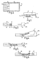
- Figure 1 shows a lamp body;
- Figure 2 shows a printed circuit board;
- Figure 3 shows a mounting bracket;
- Figure 4 shows the base part of the lamp body in a first stage of mounting on a bracket;
- Figure 5 shows the base part of the lamp body when mechanically but not electrically connected to the bracket; and
- Figure 6 shows the lamp body electrically connected to the bracket.
-
- Referring to the drawings, Figure 1 shows schematically a
lamp body 1 comprising alamp 2 mounted within a cover 3. The lamp may be of any type but will usually be a fluorescent tube type, with associated ballast and other apparatus 4. Where the light is for emergency use, abattery 5 will also generally be provided so that the lamp is powered by mains in normal operation and by the battery when mains power is disconnected. The circuitry for the lamp is provided upon a printed circuit board (PCB) 6. The printed circuit board is rigidly mounted to the luminaire body by mounts 7. As shown in Figure 2, the printedcircuit board 6 includes all or substantially all the relevant circuitry for the lamp and power supply, indicated by the area within dashed lines 8. It also includes a plurality ofterminal connections 9 formed by printing conductive track extending to the edge of the board. The tracks may be widened at their ends as shown to enable better contact to be made and the tracks make electrical contact with relevant parts of the circuit 8. Any number of terminal connections may be included as appropriate. In alternative embodiments, the board may be cut-away to form separate fingers for the terminal connections. The conductive tracks may in some embodiments be reinforced by a build up of solder, or by fixing conductive (eg. metallic) fingers or strips thereto. - The
connections 9 on the PCB may be formed by other means or materials. - The lamp body also include mechanical connection means in the form of a
slide connector 10 mounted generally at one end and a clip connector 11 mounted at the opposed end. The design of these may vary widely and their function is described further below. - A
co-operating bracket 12 is shown in Figure 3. The bracket includes anelectrical connector 13 which includes alongitudinal channel 14 such that the connector is U-shaped in cross-section. The channel is provided, on its upper or lower surfaces, with a co-operating plurality ofelectrical terminals 15. These are designed to cooperate withterminal portions 9 of the printed circuit board and may be spring mounted by leaf springs or other means such that when the end of the printed circuit board bearingterminal fingers 9 is inserted intochannel 14, theterminal connections 15 make good contact withfinger portions 9. Thechannel 14 should, of course, be of sufficient depth to receive the depth of the printed circuit board. As shown in Figure 2, the PCB may be formed with a locating slot 6a at the end bearing the terminal connections, which co-operates with an equivalent lug or other means on theconnector 13 to ensure correct spatial positioning thereof. - The channel may comprise a slot or be of other configuration.
- The bracket further comprises a
slideway 16 at one end, provided at one end with an opening 17 of sufficient width to allowslide connection 10 of the lamp body to enter. At the other end of the bracket, there is provided aclip location 18 configured to receive clip means 11 of the body. Aslide channel 19 is provided to allow clip means 11 to slide with respect to the bracket. - Figures 4 to 6 show the way in which the lamp body may be connected to the bracket.
- Firstly, the bracket is connected to a wall or ceiling, by means of screws or other means, and electrical connections are made between the
connector 13 of the bracket and cables extending through or along the wall or ceiling as appropriate. Thelamp body 1 is brought towards thebracket 12 at an angle as shown such thatslide locator 10 enters intoopening 17. Clip 11 is inserted intoclip locator 12 and the lamp body is pushed downward into the position shown in Figure 5. Note that in this position the connectors on thePCB 6 have not yet made electrical connection withconnector 13. The body is, however, mechanically connected to the bracket once it is pushed into the position of Figure 5 and will not fall out. It can only be removed by forcing clip 11 out oflocation 12 and tilting the base to remove it. - To finally make the electrical connection, the lamp body is slid (to the left in the figure) such that
PCB 6 partially enterschannel 14 and theterminals 9 on its top or bottom edge make electrical contact withrespective terminals 15 on the connector. Theslide connector 10 slides alongslideway 16 to achieve this and clip connector 11 also slides alongchannel 19. The lamp body reaches the position shown in Figure 6 in which an edge of the PCB has been inserted intochannel 14 to make electrical contact, and the lamp may be operated. The lamp body may be electrically disconnected by subsequently sliding to the right in the figure, freeingPCB 6 fromchannel 14. - Although not essential, it is preferable to provide a locking mechanism to prevent unauthorised or accidental disconnection. This may be achieved by a
screw 20, or by other means, inserted through the base oflamp body 1 intobracket 12 and optionally throughbracket 12 into the supporting wall or ceiling. This screw may require a special tool to remove it and serves to prevent relative sliding movement of the lamp body and bracket whilst it is present. - The
clips 10, 11 and their complimentary engaging/slidingmeans Clip 12 may be provided with inwardly-directed resiliently mountedfingers 12a for example, the ends of which are forced apart by clip 11 when inserted or removed with a certain force greater than normal gravitational forces, retaining the clip when the lamp body hangs normally from a ceiling-mounted bracket but enabling the body to be forcefully pulled out when required. -
Opening 17 may be of a size and shape that slideclip 10 can be inserted into it when inserted at an angle, as shown in Figure 4, but thatslide 10 is held captive when it is angularly displaced to the angular disposition of Figures 5 and 6, with the lamp body generally parallel to the bracket. - In alternative embodiments, the
PCB 6 may be rotated into and out of cooperation with thechannel 14, eg. horizontally.
Claims (10)
- A lamp assembly comprising a bracket (12) comprising mechanical (16, 17, 18, 19) and electrical (13, 14, 15) connection means for connecting to a lamp body and adapted for mounting on a surface and a lamp body (1) having means for mechanically (10, 11) and electrically (9) connecting to the bracket, the lamp body comprising a printed circuit it board (PCB) (6) bearing the circuitry for the lamp, which PCB is provided with electrical contacts, characterised in that the assembly is such that the bracket and lamp body are arranged to mechanically connect before electrical connection is made and the lamp body is arranged to slide relative to the bracket after mechanical connection has been made so that the electrical contacts of the PCB slide into and out of electrical connection with the bracket to make or break the electrical connection between the lamp body and the bracket.
- A lamp assembly as claimed in Claim 1 wherein the mechanical connection is by a snap-fit allowing a degree of relative movement after connection has been made.
- A lamp assembly as claimed in Claim 1 or Claim 2 including a locking means (20) for locking the lamp body in place after electrical connection has been made.
- A lamp assembly as claimed in any of Claims 1 to 3 wherein the electrical contacts on the PCB are conductive tracks printed thereon.
- A lamp assembly as claimed in Claim 4 wherein the conductive tracks are reinforced by a build up of solder or by conductive fingers or strips.
- A lamp assembly as claimed in any of the preceding claims wherein the PCB is arranged to slide into and out of a channel portion (14) of the bracket to make or break electrical connections.
- A lamp assembly as claimed in any of the preceding claims wherein the PCB slides axially.
- A lamp assembly as claimed in any of the preceding claims wherein the PCB comprises a tongue portion provided with electrical contacts.
- A method of testing a lamp assembly as claimed in any of the preceding claims, comprising mechanically connecting the lamp body to the bracket, testing the electrical supply at the bracket with the lamp body electrically disconnected, and then electrically connecting the lamp body to the bracket.
- A method as claimed in Claim 9 applied to an emergency lighting circuit comprising a plurality of lamp assemblies.
Applications Claiming Priority (2)
| Application Number | Priority Date | Filing Date | Title |
|---|---|---|---|
| GB9614777 | 1996-07-13 | ||
| GBGB9614777.2A GB9614777D0 (en) | 1996-07-13 | 1996-07-13 | Lamp Assemblies |
Publications (3)
| Publication Number | Publication Date |
|---|---|
| EP0818653A2 EP0818653A2 (en) | 1998-01-14 |
| EP0818653A3 EP0818653A3 (en) | 1999-01-20 |
| EP0818653B1 true EP0818653B1 (en) | 2004-06-02 |
Family
ID=10796888
Family Applications (1)
| Application Number | Title | Priority Date | Filing Date |
|---|---|---|---|
| EP97304876A Expired - Lifetime EP0818653B1 (en) | 1996-07-13 | 1997-07-03 | Lamp assembly and method of testing it |
Country Status (4)
| Country | Link |
|---|---|
| EP (1) | EP0818653B1 (en) |
| AT (1) | ATE268452T1 (en) |
| DE (1) | DE69729351D1 (en) |
| GB (1) | GB9614777D0 (en) |
Families Citing this family (6)
| Publication number | Priority date | Publication date | Assignee | Title |
|---|---|---|---|---|
| DE19954068B4 (en) * | 1999-11-10 | 2010-11-25 | Zumtobel Lighting Gmbh | lamp |
| DE10011613A1 (en) * | 2000-03-10 | 2001-09-13 | Korte Ag | Device for mounting and electrically connecting lights has light body and connection box with complementary electrical connecting elements for reversible connection by latching device |
| DE20106058U1 (en) * | 2001-04-06 | 2002-08-08 | Ceag Sicherheitstechnik Gmbh | mounter |
| WO2010049517A1 (en) * | 2008-10-31 | 2010-05-06 | Osram Gesellschaft mit beschränkter Haftung | A mounting arrangement for light sources and corresponding method |
| SE537327C2 (en) * | 2012-02-01 | 2015-04-07 | Strihl Scandinavia Ab | Easy mountable lighting fixture with fitting device |
| CN102980106A (en) * | 2012-12-06 | 2013-03-20 | 程建英 | Multi-functional bed lamp |
Family Cites Families (6)
| Publication number | Priority date | Publication date | Assignee | Title |
|---|---|---|---|---|
| AT246856B (en) * | 1963-09-11 | 1966-05-10 | Siemens Ag | lamp |
| FR2529299A1 (en) * | 1982-06-23 | 1983-12-30 | Sarlam Applique Moderne | Tubular lamp safety fitting for humid environments - uses insulating strip which is slid over line parts of fitting by removal of cover |
| GB2156062A (en) * | 1984-03-15 | 1985-10-02 | Ensel Electric Company Limited | Lighting unit |
| FR2602028B1 (en) | 1986-07-30 | 1990-12-28 | Beghelli G P B Srl | QUICK JUNCTION SYSTEM FOR LAMPS |
| DE4233570A1 (en) * | 1992-09-29 | 1994-03-31 | Koebele Lipp Lutz | Low-voltage lighting arrangement with two current rails - has modular strip of circuit board with halogen lamp on cantilever arm inserted into gap between rails above and below bar. |
| DE19504112A1 (en) * | 1995-02-08 | 1996-08-22 | Wila Leuchten Gmbh | Connector for discharge lamp having unilateral terminals |
-
1996
- 1996-07-13 GB GBGB9614777.2A patent/GB9614777D0/en active Pending
-
1997
- 1997-07-03 EP EP97304876A patent/EP0818653B1/en not_active Expired - Lifetime
- 1997-07-03 DE DE69729351T patent/DE69729351D1/en not_active Expired - Lifetime
- 1997-07-03 AT AT97304876T patent/ATE268452T1/en not_active IP Right Cessation
Also Published As
| Publication number | Publication date |
|---|---|
| EP0818653A3 (en) | 1999-01-20 |
| GB9614777D0 (en) | 1996-09-04 |
| EP0818653A2 (en) | 1998-01-14 |
| ATE268452T1 (en) | 2004-06-15 |
| DE69729351D1 (en) | 2004-07-08 |
Similar Documents
| Publication | Publication Date | Title |
|---|---|---|
| US4861273A (en) | Low-voltage miniature track lighting system | |
| KR20180121495A (en) | Connector system for lighting assembly | |
| CN111029203A (en) | Plug-in device of heavy current circuit breaker | |
| US3514590A (en) | Fluorescent luminaire | |
| KR101031015B1 (en) | A lamp socket and light appliance therof | |
| EP0818653B1 (en) | Lamp assembly and method of testing it | |
| CN1183470C (en) | SIM card holder | |
| US20090258524A1 (en) | Electrical Fixture Connection Assembly | |
| US5961335A (en) | Decentralized input/output module for a data bus | |
| GB2194033A (en) | Quick snap-on system for lamps | |
| DE102016111957A1 (en) | Electric / electronic device | |
| US20080034630A1 (en) | Holder for a Ceiling Sign | |
| KR20170123813A (en) | Lighting rail system | |
| US4298918A (en) | Fluorescent fixture socket | |
| GB2284107A (en) | Support for a light tube and method of use | |
| WO1999054973A1 (en) | Quick connect relay module | |
| JPH07502626A (en) | printed circuit board equipment | |
| WO2018021725A1 (en) | Vehicle led lamp unit | |
| US4739188A (en) | Starting circuit enclosure | |
| US4847576A (en) | Transmitter/antenna plug-in board | |
| EP3786523B1 (en) | Adapter for electrically connecting a lighting device to an electrical track, lighting system comprising such an adapter and an electrical track | |
| MX2011000548A (en) | Fluorescent lamp support. | |
| EP4033144A1 (en) | Driver for driving a light engine of a luminaire | |
| JPH09505446A (en) | Receptor for components directly connected to the board | |
| SU1173570A1 (en) | Electronic module |
Legal Events
| Date | Code | Title | Description |
|---|---|---|---|
| PUAI | Public reference made under article 153(3) epc to a published international application that has entered the european phase |
Free format text: ORIGINAL CODE: 0009012 |
|
| AK | Designated contracting states |
Kind code of ref document: A2 Designated state(s): AT BE CH DE DK ES FI FR GB GR IE IT LI LU MC NL PT SE |
|
| PUAL | Search report despatched |
Free format text: ORIGINAL CODE: 0009013 |
|
| AK | Designated contracting states |
Kind code of ref document: A3 Designated state(s): AT BE CH DE DK ES FI FR GB GR IE IT LI LU MC NL PT SE |
|
| RHK1 | Main classification (correction) |
Ipc: F21V 23/06 |
|
| 17P | Request for examination filed |
Effective date: 19990713 |
|
| AKX | Designation fees paid |
Free format text: AT BE CH DE DK ES FI FR GB GR IE IT LI LU MC NL PT SE |
|
| GRAP | Despatch of communication of intention to grant a patent |
Free format text: ORIGINAL CODE: EPIDOSNIGR1 |
|
| RTI1 | Title (correction) |
Free format text: LAMP ASSEMBLY AND METHOD OF TESTING IT |
|
| RTI1 | Title (correction) |
Free format text: LAMP ASSEMBLY AND METHOD OF TESTING IT |
|
| GRAS | Grant fee paid |
Free format text: ORIGINAL CODE: EPIDOSNIGR3 |
|
| GRAA | (expected) grant |
Free format text: ORIGINAL CODE: 0009210 |
|
| AK | Designated contracting states |
Kind code of ref document: B1 Designated state(s): AT BE CH DE DK ES FI FR GB GR IE IT LI LU MC NL PT SE |
|
| PG25 | Lapsed in a contracting state [announced via postgrant information from national office to epo] |
Ref country code: NL Free format text: LAPSE BECAUSE OF FAILURE TO SUBMIT A TRANSLATION OF THE DESCRIPTION OR TO PAY THE FEE WITHIN THE PRESCRIBED TIME-LIMIT Effective date: 20040602 Ref country code: LI Free format text: LAPSE BECAUSE OF FAILURE TO SUBMIT A TRANSLATION OF THE DESCRIPTION OR TO PAY THE FEE WITHIN THE PRESCRIBED TIME-LIMIT Effective date: 20040602 Ref country code: IT Free format text: LAPSE BECAUSE OF FAILURE TO SUBMIT A TRANSLATION OF THE DESCRIPTION OR TO PAY THE FEE WITHIN THE PRESCRIBED TIME-LIMIT;WARNING: LAPSES OF ITALIAN PATENTS WITH EFFECTIVE DATE BEFORE 2007 MAY HAVE OCCURRED AT ANY TIME BEFORE 2007. THE CORRECT EFFECTIVE DATE MAY BE DIFFERENT FROM THE ONE RECORDED. Effective date: 20040602 Ref country code: FR Free format text: LAPSE BECAUSE OF FAILURE TO SUBMIT A TRANSLATION OF THE DESCRIPTION OR TO PAY THE FEE WITHIN THE PRESCRIBED TIME-LIMIT Effective date: 20040602 Ref country code: FI Free format text: LAPSE BECAUSE OF FAILURE TO SUBMIT A TRANSLATION OF THE DESCRIPTION OR TO PAY THE FEE WITHIN THE PRESCRIBED TIME-LIMIT Effective date: 20040602 Ref country code: CH Free format text: LAPSE BECAUSE OF FAILURE TO SUBMIT A TRANSLATION OF THE DESCRIPTION OR TO PAY THE FEE WITHIN THE PRESCRIBED TIME-LIMIT Effective date: 20040602 Ref country code: BE Free format text: LAPSE BECAUSE OF FAILURE TO SUBMIT A TRANSLATION OF THE DESCRIPTION OR TO PAY THE FEE WITHIN THE PRESCRIBED TIME-LIMIT Effective date: 20040602 Ref country code: AT Free format text: LAPSE BECAUSE OF FAILURE TO SUBMIT A TRANSLATION OF THE DESCRIPTION OR TO PAY THE FEE WITHIN THE PRESCRIBED TIME-LIMIT Effective date: 20040602 |
|
| REG | Reference to a national code |
Ref country code: GB Ref legal event code: FG4D |
|
| REG | Reference to a national code |
Ref country code: CH Ref legal event code: EP |
|
| PG25 | Lapsed in a contracting state [announced via postgrant information from national office to epo] |
Ref country code: LU Free format text: LAPSE BECAUSE OF NON-PAYMENT OF DUE FEES Effective date: 20040703 |
|
| PG25 | Lapsed in a contracting state [announced via postgrant information from national office to epo] |
Ref country code: IE Free format text: LAPSE BECAUSE OF NON-PAYMENT OF DUE FEES Effective date: 20040705 |
|
| REF | Corresponds to: |
Ref document number: 69729351 Country of ref document: DE Date of ref document: 20040708 Kind code of ref document: P |
|
| REG | Reference to a national code |
Ref country code: IE Ref legal event code: FG4D |
|
| PG25 | Lapsed in a contracting state [announced via postgrant information from national office to epo] |
Ref country code: MC Free format text: LAPSE BECAUSE OF NON-PAYMENT OF DUE FEES Effective date: 20040731 |
|
| PG25 | Lapsed in a contracting state [announced via postgrant information from national office to epo] |
Ref country code: SE Free format text: LAPSE BECAUSE OF FAILURE TO SUBMIT A TRANSLATION OF THE DESCRIPTION OR TO PAY THE FEE WITHIN THE PRESCRIBED TIME-LIMIT Effective date: 20040902 Ref country code: GR Free format text: LAPSE BECAUSE OF FAILURE TO SUBMIT A TRANSLATION OF THE DESCRIPTION OR TO PAY THE FEE WITHIN THE PRESCRIBED TIME-LIMIT Effective date: 20040902 Ref country code: DK Free format text: LAPSE BECAUSE OF FAILURE TO SUBMIT A TRANSLATION OF THE DESCRIPTION OR TO PAY THE FEE WITHIN THE PRESCRIBED TIME-LIMIT Effective date: 20040902 |
|
| PG25 | Lapsed in a contracting state [announced via postgrant information from national office to epo] |
Ref country code: DE Free format text: LAPSE BECAUSE OF FAILURE TO SUBMIT A TRANSLATION OF THE DESCRIPTION OR TO PAY THE FEE WITHIN THE PRESCRIBED TIME-LIMIT Effective date: 20040903 |
|
| PG25 | Lapsed in a contracting state [announced via postgrant information from national office to epo] |
Ref country code: ES Free format text: LAPSE BECAUSE OF FAILURE TO SUBMIT A TRANSLATION OF THE DESCRIPTION OR TO PAY THE FEE WITHIN THE PRESCRIBED TIME-LIMIT Effective date: 20040913 |
|
| REG | Reference to a national code |
Ref country code: CH Ref legal event code: PL |
|
| NLV1 | Nl: lapsed or annulled due to failure to fulfill the requirements of art. 29p and 29m of the patents act | ||
| REG | Reference to a national code |
Ref country code: IE Ref legal event code: MM4A |
|
| PLBE | No opposition filed within time limit |
Free format text: ORIGINAL CODE: 0009261 |
|
| STAA | Information on the status of an ep patent application or granted ep patent |
Free format text: STATUS: NO OPPOSITION FILED WITHIN TIME LIMIT |
|
| 26N | No opposition filed |
Effective date: 20050303 |
|
| EN | Fr: translation not filed | ||
| PG25 | Lapsed in a contracting state [announced via postgrant information from national office to epo] |
Ref country code: PT Free format text: LAPSE BECAUSE OF NON-PAYMENT OF DUE FEES Effective date: 20041102 |
|
| REG | Reference to a national code |
Ref country code: GB Ref legal event code: 732E Free format text: REGISTERED BETWEEN 20141106 AND 20141112 |
|
| PGFP | Annual fee paid to national office [announced via postgrant information from national office to epo] |
Ref country code: GB Payment date: 20160624 Year of fee payment: 20 |
|
| REG | Reference to a national code |
Ref country code: GB Ref legal event code: PE20 Expiry date: 20170702 |
|
| PG25 | Lapsed in a contracting state [announced via postgrant information from national office to epo] |
Ref country code: GB Free format text: LAPSE BECAUSE OF EXPIRATION OF PROTECTION Effective date: 20170702 |