EP0818609A2 - Valve timing control devices - Google Patents
Valve timing control devices Download PDFInfo
- Publication number
- EP0818609A2 EP0818609A2 EP97202138A EP97202138A EP0818609A2 EP 0818609 A2 EP0818609 A2 EP 0818609A2 EP 97202138 A EP97202138 A EP 97202138A EP 97202138 A EP97202138 A EP 97202138A EP 0818609 A2 EP0818609 A2 EP 0818609A2
- Authority
- EP
- European Patent Office
- Prior art keywords
- rotor
- cam shaft
- passage
- housing
- angular phase
- Prior art date
- Legal status (The legal status is an assumption and is not a legal conclusion. Google has not performed a legal analysis and makes no representation as to the accuracy of the status listed.)
- Granted
Links
Images
Classifications
-
- F—MECHANICAL ENGINEERING; LIGHTING; HEATING; WEAPONS; BLASTING
- F01—MACHINES OR ENGINES IN GENERAL; ENGINE PLANTS IN GENERAL; STEAM ENGINES
- F01L—CYCLICALLY OPERATING VALVES FOR MACHINES OR ENGINES
- F01L1/00—Valve-gear or valve arrangements, e.g. lift-valve gear
- F01L1/34—Valve-gear or valve arrangements, e.g. lift-valve gear characterised by the provision of means for changing the timing of the valves without changing the duration of opening and without affecting the magnitude of the valve lift
- F01L1/344—Valve-gear or valve arrangements, e.g. lift-valve gear characterised by the provision of means for changing the timing of the valves without changing the duration of opening and without affecting the magnitude of the valve lift changing the angular relationship between crankshaft and camshaft, e.g. using helicoidal gear
- F01L1/3442—Valve-gear or valve arrangements, e.g. lift-valve gear characterised by the provision of means for changing the timing of the valves without changing the duration of opening and without affecting the magnitude of the valve lift changing the angular relationship between crankshaft and camshaft, e.g. using helicoidal gear using hydraulic chambers with variable volume to transmit the rotating force
- F01L2001/3445—Details relating to the hydraulic means for changing the angular relationship
- F01L2001/34483—Phaser return springs
-
- Y—GENERAL TAGGING OF NEW TECHNOLOGICAL DEVELOPMENTS; GENERAL TAGGING OF CROSS-SECTIONAL TECHNOLOGIES SPANNING OVER SEVERAL SECTIONS OF THE IPC; TECHNICAL SUBJECTS COVERED BY FORMER USPC CROSS-REFERENCE ART COLLECTIONS [XRACs] AND DIGESTS
- Y10—TECHNICAL SUBJECTS COVERED BY FORMER USPC
- Y10T—TECHNICAL SUBJECTS COVERED BY FORMER US CLASSIFICATION
- Y10T74/00—Machine element or mechanism
- Y10T74/21—Elements
- Y10T74/2101—Cams
- Y10T74/2102—Adjustable
Definitions
- the invention relates to valve timing control devices for controlling the angular phase difference between the crank shaft and the cam shaft of a combustion engine.
- valve timing is determined by a mechanism driven by cam shafts according to a characteristic of the engine or its operation.
- the combustion changes in response to the rotational speed, so it is difficult to obtain optimum valve timing throughout the whole rotational range. Therefore, a device which is able to change the valve timing in response to the condition of the engine is desirable.
- JP laid-open publication 6(1994)-14403 discloses helical splines on both a timing sprocket and a cam shaft-side member fixed to an end of a cam shaft having cams for opening and closing valves and projecting from the cylinder head of a combustion engine.
- the timing sprocket is driven by the rotational torque from a crank and is rotatably mounted on the cam shaft.
- a piston provided with inner and outer circumferential helical spines for engaging the respective angular splines of the timing sprocket and the cam shaft-side member is disposed between the timing sprocket and the cam shaft-side member and transmits the rotational torque from the timing sprocket to the cam shaft-side member.
- Pressure chambers are formed at both sides of the piston between the timing sprocket and the camshaft-side member and the piston is axially moved by controlling the fluid pressure in the pressure chambers.
- the piston, the pressure chambers and respective angular splines of the timing sprocket and the cam shaft-side member function as an angular phase converting mechanism and an angular phase difference between the crank shaft (the timing sprocket) and the cam shaft is controlled.
- US 4858572 discloses a rotor which is fixed on the end of the cam shaft, a drive member which is driven by the rotational torque from the crank shaft and which is rotatably mounted on the cam shaft, a plurality of chambers between the drive member and the rotor and vanes which are mounted to the rotor and which are extended outwardly therefrom in the radial direction into the chambers to divide each of the chambers into a first pressure chamber and a second pressure chamber. Fluid under pressure is supplied to a selected one of the first pressure chamber and the second pressure chamber.
- the vanes and the pressure chambers function as an angular phase converting mechanism and control the angular phase difference between the crank shaft (the drive member) and the cam shaft.
- passages for supplying the fluid to the pressure chambers are formed in the cam shaft. These passages have to be always communicated to the pressure chambers regardless of the angular phase difference between the crank shaft (the timing sprocket or the drive member) and the cam shaft.
- there is a circular groove which communicates between the pressure chambers and the passages on the outer circumferential surface of the cam shaft-side member (on which the timing sprocket is rotatably fitted) and the outer circumferential surface of the end of the cam shaft (on which the rotor is fixed).
- the axle length of these portions has to be long in order to prevent fluid from leaking through the circular groove.
- the axial length of the end of the cam shaft which projects from the cylinder head has to be increased to ensure the requisite sealing surface, and thereby the size of the whole engine is increased.
- the invention provides a valve timing control device which comprises a rotor for fixing on a cam shaft and having a circular groove opposing an end surface of the cam shaft.
- the circular groove communicates to a passage in the cam shaft.
- a housing surrounds the rotor.
- An angular phase converting mechanism is disposed between the rotor and the housing for transmitting rotational torque from the housing to the rotor and providing an angular phase difference between the rotor and the housing.
- Fluid supplying means supplies fluid under pressure to the angular phase converting mechanism through the passage and the circular groove. This arrangement enables the whole engine to be kept relatively short.
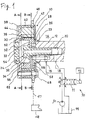
- a device 10 has a cam shaft 12 which is provided with a plurality of cam portions (not shown) driving valves (not shown) is rotatably supported on a cylinder head 14 of an engine at its plural journal portions (not shown). Passages 16, 18 are formed in the cam shaft 12 and the passage 18 communicates to a central hole 20 of the cam shaft 12.
- the rotor 22 has a flange portion 22a which is extended inwards in the radial direction and which is nipped between an end surface 26 of the cam shaft 12 and a head portion 32 of the bolt 24.
- a circular groove 28 is formed thereon and is communicated to the passage 16.
- a cylindrical projecting portion 23 is formed and is mounted on the projecting end of the cam shaft 12.
- a cylindrical portion 30 in which the head portion 32 of the bolt 24 is located is formed.
- the bolt 24 has a hole 34 which penetrates along the axial center and which communicates to the passage 18 through the central hole 20.
- a cylindrical housing member 40 having a inner bore 40a is rotatably mounted on the outer circumferential surface of the cylindrical portion 30 of the rotor 22 so as to surround the rotor 22.
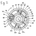
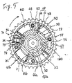
- the housing member 40 has the same axial length as the cylindrical portion 30 of the rotor 56 and is provided with five grooves 40b which are outwardly extended from the inner bore 40a in the radial direction and which are separated in the circumferential direction by partition wall portions 66 as shown in Fig. 2 and Fig. 3. Hollow portions 67 are formed in the partition wall portions 66 for decreasing the weight and inertial force of the housing member 40, respectively.
- the housing member 40 is further provided with three penetrating holes in the axial direction which are separated from each other at regular intervals
- a gear portion 46 is formed on the housing member 40 and rotational torque is transmitted to the gear portion 46 (the housing 40) via a chain 47 from a crank shaft 48 of the engine.
- a circular front plate 44 which is provided with four female screw holes in the axial direction is disposed adjacent to one side surfaces of the cylindrical portion 30 of the rotor 22 and the housing member 40 so as to be able to contact with both surfaces at its one side surface.
- a circular rear plate 42 which is provided with four penetrating holes in the axial direction is disposed adjacent to the other side surfaces of the cylindrical portion 30 of the rotor 22 and the housing member 40 so as to be able to contact with both surfaces at its one side surface.
- Each of the female holes of the front plate 44, each of the hollow portions 67 of the housing member 40 and each of the screw holes of the rear plate 42 are coaxially arranged each other and a bolt 48 is fitted into each of the coaxially arranged holes and hollow portions 67.
- Each of the bolts 48 is screwed into each of the female screw holes of the front plate 44.
- the rotor 22, the housing member 40, the rear plate 42 and the front plate 60 are united.
- One side surface of the front plate 44 is fluid-tightly pressed onto one side surfaces of cylindrical portion 30 of the rotor 22 and the housing member 40 and one side surface of the rear plate 42 is fluid-tightly pressed onto the other side surfaces of the cylindrical portion 30 of the rotor 22 and the housing member 40.
- a plug 54 is fluid-tightly fitted into a central opening of the front plate 44 and thereby a sealed space 56 which in communicated to the passage 18 is formed in the cylindrical portion 30 of the rotor 22.
- each of chambers 68 which are separated in the cicumferential direction and each of which has a pair of circumferentially opposed walls 66a, 66b are defined among the rotor 22, the housing member 40, the front plate 44 and the rear plate 42.
- On the outer circumferential portion of the cylindrical portion 30 of the rotor 56 four grooves 31 which are extended inwardly therefrom in the radial direction and which are separated in the cicumferential direction are formed thereon.
- Four vanes 38 which are extended outwardly in the radial direction into the chambers 68 are mounted in the grooves 31, respectively.
- each of chambers 68 is divided into a first pressure chamber 60 and a second pressure chamber 64, both of which are fluid-tightly separated from each other.
- Each of the vanes 38 is normally urged outwards in the radial direction by a plate spring 36 which is disposed between each of the vanes 38 and the bottom surface of each of the grooves 31.
- the rotor 22 is provided with four first passages 58 and four second passages 62.
- One end of each of the first passages 58 is communicated with the circular groove 28 and the other end of each of the first passages 58 is communicated with each of the first pressure chambers 60.
- one end of each of the second passages 62 is communicated with the space 56 and the other end of each of the second passages 62 is communicated with each of the second pressure chambers 64.
- a locking mechanism 70 for connecting the housing member 40 and the rotor 22 is disposed in the housing member 40.
- the locking mechanism 70 includes a piston pin 76 which is slidably fitted into a penetrating radial hole 72 formed in one of the partition wall portion 66. Outer end of the radial hole 72 is closed by a cover 80 and a spring 74 which urges the piston pin 76 inwardly is disposed between the cover 80 and the piston pin 76.
- a fitting hole 78 communicating to the space 56 via a hole 82 is formed on the cylindrical portion 30 of the rotor 22 so that the piston pin 76 is fitted into the fitting hole 78 when the valve timing control device 10 is in the position of the maximum retarded condition in which the vanes 38 contacts with the opposed walls 66b as shown in Fig. 2.
- a fluid supplying device 90 is comprised of a changeover valve 91, a fluid pump 92 and a controller 93.
- the changeover valve 91 is an electromagnetic valve which is 4 ports - 3 positions type.
- the pump 92 may be a pump for lubricating the engine.
- the passage 16 is communicated to a A port of the changeover valve 91 and the passage 18 is communicated to a B port of the changeover valve 91.
- a P port of the changeover valve 91 is communicated to a discharge portion the fluid pump 92 and a R port of the changeover valve 91 is communicated to a reservoir 94.
- the position of the changeover valve 91 is controlled by the controller 93 so that a first condition in which the discharged fluid from the pump 92 is supplied to the passage 16 and in which the passage 18 is communicated to the reservoir 94, a second condition in which the communication between the passages 16, 18 and the pump 92 and the reservoir 94 are interrupted, respectively and in which the discharged fluid from the pump 92 is supplied to the reservoir 94 and a third condition in which the discharged fluid from the pump 92 is supplied to the passage 18 and in which the passage 16 is communicated to the reservoir 94 are selectively obtained.
- the controller 93 controls the above conditions of the changeover valve 91 based on parameter signals which are an engine speed, an amount of opening of a throttle valve (not shown) and so on.
- valve timing control device having the above structure
- the rotational torque is transmitted from the crank shaft 48 to the housing member 40 through the chain 47 and the gear portion 46 and thereby, the housing member 40 is rotated clockwise in Fig. 2 and Fig. 3.
- the rotational torque of the housing member 40 is transmitted to the rotor 22 via the vanes 38.
- the cam shaft 12 is rotated clockwise in Fig. 2 and Fig. 3 and the valves (not shown) are opened and closed.
- the changeover valve 91 since the changeover valve 91 is in the first condition, the rotational torque of the housing member 40 is transmitted to the rotor 22 via the piston pin 76.
- the pressurized fluid is supplied from the pump 92 to the second pressure chambers 64 via the passage 18, the central hole 20, the hole 34, the space 56 and the second passages 62.
- the pressurized fluid is applied to the fitting hole 78 via the hole 82 and then the piston pin 76 is moved toward the radial hole 72 against the urging force of the spring 74.
- the engagement between the housing member 40 and the rotor 22 via the piston pin 76 is released and the relative movement between the housing member 40 and the rotor 22 is allowed.
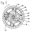
- the vanes 38 and the rotor 22 are rotated clockwise relative to the housing member 40 in Fig. 2 and Fig.
- valve timing control device is in the position of the maximum advanced condition in which the angular phase of the cam shaft 12 is advanced relative to that of the crank shaft 48 by a predetermined maximum value.
- the pressurized fluid is supplied from the pump 92 to the first pressure chambers 66 by the changeover valve 91 changed to the first condition via the passage 16 and the first passages 58, the vanes 38 and the rotor 22 are rotated counterclockwise relative to the housing member 40 in Fig. 2 and Fig. 3 until the vanes 38 are contacted with the walls 66b.
- the valve timing control device is in the position of the maximum retarded condition in which the angular phase of the cam shaft 12 is retarded relative to that of the crank shaft 48 by a predetermined maximum value.
- the vanes 38 can be stopped in any position (intermediate advanced position) between the maximum advanced position and the maximum retarded position. This requires that balance be achieved between the fluid pressure of the first pressure chambers 60 and the fluid pressure of the second pressure chambers 64 when the vanes 38 have achieved an arbitrary position.
- the amount of the advance can therefore be set to any value between a zero level and a maximum level.
- the opening and closing timing of the valves (not shown) driven by the cam shaft 12 is adjusted and the angular phase difference between the crank shaft 48 and the cam shaft 12 is adjusted.
- the circular groove 28 is formed on one surface of the flange portion 22a of the rotor 22 which is opposite to the end surface 26 of the cam shaft 12.
- the requisite sealing surface for the circular groove 28 is ensured by one surface of the flange portion 22a and the end surface 26, it is able to shorten the axial length of the cylindrical projecting portion 23.
- the cylindrical portion 30 on which the housing member 40 is mounted is formed on the rotor 22, it is able to dispose the head portion 32 of the bolt 24 in the cylindrical portion 30. Accordingly, it is able to reduce the axial length of the end of the cam shaft 12 which is projected from the cylinder head 14 and therefore it is able to miniaturize the engine.
- the hole 34 of the bolt 24 and the space 56 are used as a part of the passage for supplying the fluid to the second pressure chambers 64. Therefore, it is able to efficiently use the restricted space of the valve timing control device. Furthermore, the housing member 40, the front plate 44 and the rear plate 42 are united by the bolts 48 which are screwed from the side of the rear plate 44 being adjacent to the cylinder head 14. Therefore, since it is not able to remove the bolts 48 before the bolt 24 is removed, it is prevented that the bolts 48 are carelessly removed at the maintenance of the engine.
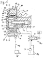
- a coil spring 100 is disposed in the cylindrical portion 30 of the rotor 22.
- One end of the coil spring 100 is engaged with a hole 86 which is formed on the front plate 44.
- the other end of the coil spring 100 is engaged with an axial hole 88 which is formed on the inner circumference of the cylindrical portion 30.
- the coil spring 100 normally urges the rotor 22 and the vanes 38 (the cam shaft 12) clockwise, namely, toward the advance direction.
- the cam shaft 12 normally receives reaction to the retard direction.
- the open and close timing of the exhaust valves is retarded.
- the exhaust valves and the intake valves open simultaneously and mixture gas is discharged without combusting. Therefore, there is in danger that it becomes difficult to start the engine and that atmosphere is contaminated. In this embodiment, it is able to overcome these drawbacks. Further, according to this embodiment, since the coil spring 100 is disposed in the space 56 and is always in the fluid (oil) , the coil spring 100 is prevented from oxidizing and its torsional operation is maintained.
Landscapes
- Engineering & Computer Science (AREA)
- Mechanical Engineering (AREA)
- General Engineering & Computer Science (AREA)
- Valve Device For Special Equipments (AREA)
- Valve-Gear Or Valve Arrangements (AREA)
- Lubrication Of Internal Combustion Engines (AREA)
Abstract
Description
Claims (9)
- A valve timing control device (10) comprising:a rotor (22) for fixing on a cam shaft (12) and having a circular groove (28) opposing an end surface (26) of the cam shaft (12), the circular groove (28) communicating to a passage (16) in the cam shaft (12),a housing (40) surrounding the rotor (22),an angular phase converting mechanism between the rotor (22) and the housing (40) for transmitting rotational torque from the housing (40) to the rotor (22) and providing an angular phase difference between the rotor (22) and the housing (40) andfluid supply means (91,92) for the angular phase converting mechanism through the passage (16) and the circular groove (28).
- A device according to claim 1, wherein the passage (16) communicates with the angular phase converting mechanism via the groove (28) and a second passage (18) communicating with the angular phase converting mechanism via a supply passage (58) in the rotor (22) are formed in the cam shaft (12) and the angular phase converting mechanism operates in response to the difference between the fluid pressures in the first and second passages (16,18).
- A device according to claim 1 or claim 2, wherein the angular phase converting mechanism includes a chamber (68) between the housing (40) and the rotor (22) and having a pair of circumferentially opposed walls (66a,66b) and a vane (38) mounted on the rotor (22) and extending outwardly therefrom in the radial direction into the chamber (68) so as to divide the chamber (68) into a first pressure chamber 60 and a second pressure chamber (64), and the fluid supplying means supplies pressure to chambers (60,64).
- A device according to claim 3, wherein hollow portions (67) are formed in the walls (66a,66b).
- A device according to any preceding claim, wherein the rotor (22) is fixed to the cam shaft (12) via a bolt (24) which has a hole (34) as a supply passage.
- A device according to any preceding claim, wherein the rotor (22) is provided with a cylindrical portion (30) which extends away from the cam shaft (12) and the housing (40) is rotatably mounted on the cylindrical portion (30).
- A device according to claim 6, wherein the side of the cylindrical portion (30) constitutes a part of the supply passage.
- A device according to claim 6 or claim 7, wherein an elastic member (100) which urges the rotor (22) in the rotational direction of the cam shaft (12) is disposed in the cylindrical portion (30) of the rotor (22).
- A device according to any preceding claim, wherein the fluid supply means includes a pump (92), an electromagnetic changeover valve (91) alternately connected to the first passage (16) and the second passage (18), and a controller (93) for the position of the valve (91).
Applications Claiming Priority (3)
| Application Number | Priority Date | Filing Date | Title |
|---|---|---|---|
| JP18225396A JP3888395B2 (en) | 1996-07-11 | 1996-07-11 | Valve timing control device |
| JP18225396 | 1996-07-11 | ||
| JP182253/96 | 1996-07-11 |
Publications (3)
| Publication Number | Publication Date |
|---|---|
| EP0818609A2 true EP0818609A2 (en) | 1998-01-14 |
| EP0818609A3 EP0818609A3 (en) | 1998-01-28 |
| EP0818609B1 EP0818609B1 (en) | 2002-10-09 |
Family
ID=16115032
Family Applications (1)
| Application Number | Title | Priority Date | Filing Date |
|---|---|---|---|
| EP97202138A Expired - Lifetime EP0818609B1 (en) | 1996-07-11 | 1997-07-11 | Valve timing control devices |
Country Status (4)
| Country | Link |
|---|---|
| US (1) | US5813378A (en) |
| EP (1) | EP0818609B1 (en) |
| JP (1) | JP3888395B2 (en) |
| DE (1) | DE69716175T2 (en) |
Cited By (8)
| Publication number | Priority date | Publication date | Assignee | Title |
|---|---|---|---|---|
| DE19820653A1 (en) * | 1998-05-08 | 1999-11-11 | Schaeffler Waelzlager Ohg | Variable valve timing for IC engine |
| EP1384860A2 (en) * | 1998-12-07 | 2004-01-28 | Mitsubishi Denki Kabushiki Kaisha | A vane type hydraulic actuator |
| EP1703088A1 (en) * | 2005-03-15 | 2006-09-20 | Aisin Seiki Kabushiki Kaisha | Variable valve time control device |
| EP1843012A2 (en) * | 2002-12-21 | 2007-10-10 | Schaeffler KG | Combustion engine with a device for hydraulic rotation angle adjustment of the camshaft in relation to the crankshaft and a vacuum pump for a servo user, in particular for a braking power intensifier |
| US7886704B2 (en) | 2006-02-18 | 2011-02-15 | Schaeffler Technologies Gmbh & Co. Kg | Apparatus for the variable setting of the control times of gas exchange valves of an internal combustion engine |
| DE10062148B4 (en) * | 1999-12-15 | 2014-02-13 | Denso Corporation | Valve timing adjustment device for an internal combustion engine |
| DE10339669B4 (en) * | 2002-08-28 | 2016-01-28 | Aisin Seiki K.K. | Valve timing control device |
| DE19849959B4 (en) * | 1997-10-30 | 2016-07-14 | Aisin Seiki K.K. | Valve timing control device |
Families Citing this family (15)
| Publication number | Priority date | Publication date | Assignee | Title |
|---|---|---|---|---|
| JP3801747B2 (en) * | 1997-09-29 | 2006-07-26 | アイシン精機株式会社 | Valve timing control device |
| US6170447B1 (en) * | 1997-11-06 | 2001-01-09 | Ina Schaeffler Ohg | Inner seal for a camshaft adjusting device in an internal combustion engine, specially a blade cell adjusting device |
| US6263843B1 (en) | 1998-03-25 | 2001-07-24 | Unisia Jecs Corporation | Valve timing control device of internal combustion engine |
| US6311654B1 (en) * | 1998-07-29 | 2001-11-06 | Denso Corporation | Valve timing adjusting device |
| DE19932299B4 (en) * | 1999-07-10 | 2009-05-07 | Schaeffler Kg | Device for adjusting the angle of rotation of a camshaft relative to the crankshaft of an internal combustion engine |
| DE19936921A1 (en) * | 1999-08-05 | 2001-02-08 | Schaeffler Waelzlager Ohg | Device for changing the timing of gas exchange valves of an internal combustion engine, in particular hydraulic camshaft adjusting device in the type of a rotary piston |
| US6176210B1 (en) * | 1999-09-14 | 2001-01-23 | Delphi Technologies, Inc. | Axially-compact cam phaser having an inverted bearing |
| US6267089B1 (en) * | 1999-09-24 | 2001-07-31 | Ina Walzlager Schaeffler Ohg | Appliance for modifying the timing of gas-exchange valves of an internal combustion engine, in particular hydraulic camshaft adjustment device of rotary piston type |
| JP3871478B2 (en) * | 1999-10-14 | 2007-01-24 | 株式会社日立製作所 | Valve timing changing device for internal combustion engine |
| DE19963094B4 (en) * | 1999-12-24 | 2014-08-21 | Schaeffler Technologies Gmbh & Co. Kg | Device for changing the timing of gas exchange valves of an internal combustion engine, in particular hydraulic camshaft adjusting device in rotary piston type |
| US6412462B1 (en) | 2000-01-18 | 2002-07-02 | Delphi Technologies, Inc. | Cam phaser apparatus having a stator integral with a back plate or a front cover plate |
| JP4159241B2 (en) * | 2000-11-30 | 2008-10-01 | 株式会社デンソー | Valve timing adjusting device for internal combustion engine |
| JP4423799B2 (en) | 2001-03-22 | 2010-03-03 | アイシン精機株式会社 | Valve timing control device |
| WO2012094324A1 (en) | 2011-01-04 | 2012-07-12 | Hilite Germany Gmbh | Valve timing control apparatus and method |
| US9228455B1 (en) | 2013-03-14 | 2016-01-05 | Brunswick Corporation | Outboard motors and marine engines having cam phaser arrangements |
Citations (2)
| Publication number | Priority date | Publication date | Assignee | Title |
|---|---|---|---|---|
| US4858572A (en) | 1987-09-30 | 1989-08-22 | Aisin Seiki Kabushiki Kaisha | Device for adjusting an angular phase difference between two elements |
| JPH0614403A (en) | 1992-06-23 | 1994-01-21 | Toyo Electric Mfg Co Ltd | Current collector for electric railcar |
Family Cites Families (8)
| Publication number | Priority date | Publication date | Assignee | Title |
|---|---|---|---|---|
| DE2825326A1 (en) * | 1978-06-09 | 1979-12-20 | Daimler Benz Ag | TORQUE TRANSFER DEVICE |
| DE4237193A1 (en) * | 1992-11-04 | 1994-05-05 | Bosch Gmbh Robert | Method for controlling a device for the relative rotation of a shaft and device for the relative rotation of the shaft of an internal combustion engine |
| JPH0771278A (en) * | 1993-08-31 | 1995-03-14 | Aisin Seiki Co Ltd | Valve timing controller of engine |
| IT1271511B (en) * | 1993-10-06 | 1997-05-30 | Carraro Spa | PHASE VARIATOR BETWEEN THE CRANKSHAFT AND THE CAMSHAFT OF AN INTERNAL COMBUSTION ENGINE |
| JPH07259516A (en) * | 1994-03-25 | 1995-10-09 | Aisin Seiki Co Ltd | Valve timing control device |
| JP3820478B2 (en) * | 1994-05-13 | 2006-09-13 | 株式会社デンソー | Vane type rotational phase adjuster |
| US5588404A (en) * | 1994-12-12 | 1996-12-31 | General Motors Corporation | Variable cam phaser and method of assembly |
| GB2302391B (en) * | 1995-06-14 | 1999-08-18 | Nippon Denso Co | Control apparatus for varying the rotational or angular phase between two rotational shafts |
-
1996
- 1996-07-11 JP JP18225396A patent/JP3888395B2/en not_active Expired - Lifetime
-
1997
- 1997-07-11 EP EP97202138A patent/EP0818609B1/en not_active Expired - Lifetime
- 1997-07-11 US US08/893,481 patent/US5813378A/en not_active Expired - Lifetime
- 1997-07-11 DE DE69716175T patent/DE69716175T2/en not_active Expired - Lifetime
Patent Citations (2)
| Publication number | Priority date | Publication date | Assignee | Title |
|---|---|---|---|---|
| US4858572A (en) | 1987-09-30 | 1989-08-22 | Aisin Seiki Kabushiki Kaisha | Device for adjusting an angular phase difference between two elements |
| JPH0614403A (en) | 1992-06-23 | 1994-01-21 | Toyo Electric Mfg Co Ltd | Current collector for electric railcar |
Cited By (10)
| Publication number | Priority date | Publication date | Assignee | Title |
|---|---|---|---|---|
| DE19849959B4 (en) * | 1997-10-30 | 2016-07-14 | Aisin Seiki K.K. | Valve timing control device |
| DE19820653A1 (en) * | 1998-05-08 | 1999-11-11 | Schaeffler Waelzlager Ohg | Variable valve timing for IC engine |
| EP1384860A2 (en) * | 1998-12-07 | 2004-01-28 | Mitsubishi Denki Kabushiki Kaisha | A vane type hydraulic actuator |
| EP1384860A3 (en) * | 1998-12-07 | 2004-03-03 | Mitsubishi Denki Kabushiki Kaisha | A vane type hydraulic actuator |
| DE10062148B4 (en) * | 1999-12-15 | 2014-02-13 | Denso Corporation | Valve timing adjustment device for an internal combustion engine |
| DE10339669B4 (en) * | 2002-08-28 | 2016-01-28 | Aisin Seiki K.K. | Valve timing control device |
| EP1843012A2 (en) * | 2002-12-21 | 2007-10-10 | Schaeffler KG | Combustion engine with a device for hydraulic rotation angle adjustment of the camshaft in relation to the crankshaft and a vacuum pump for a servo user, in particular for a braking power intensifier |
| EP1843012A3 (en) * | 2002-12-21 | 2010-01-06 | Schaeffler KG | Combustion engine with a device for hydraulic rotation angle adjustment of the camshaft in relation to the crankshaft and a vacuum pump for a servo user, in particular for a braking power intensifier |
| EP1703088A1 (en) * | 2005-03-15 | 2006-09-20 | Aisin Seiki Kabushiki Kaisha | Variable valve time control device |
| US7886704B2 (en) | 2006-02-18 | 2011-02-15 | Schaeffler Technologies Gmbh & Co. Kg | Apparatus for the variable setting of the control times of gas exchange valves of an internal combustion engine |
Also Published As
| Publication number | Publication date |
|---|---|
| JP3888395B2 (en) | 2007-02-28 |
| EP0818609A3 (en) | 1998-01-28 |
| EP0818609B1 (en) | 2002-10-09 |
| JPH1030411A (en) | 1998-02-03 |
| US5813378A (en) | 1998-09-29 |
| DE69716175T2 (en) | 2003-03-13 |
| DE69716175D1 (en) | 2002-11-14 |
Similar Documents
| Publication | Publication Date | Title |
|---|---|---|
| EP0818609B1 (en) | Valve timing control devices | |
| EP2320037B1 (en) | Camshaft phasing device | |
| EP0848141B1 (en) | Valve timing control device | |
| EP0821138B1 (en) | Valve timing control devices | |
| JPH11132014A (en) | Valve open/close timing control device | |
| US5943989A (en) | Valve timing control device | |
| KR20110041420A (en) | Valve timing adjuster | |
| JPH10110603A (en) | Valve timing adjusting device for internal combustion engine | |
| EP0818610B1 (en) | Valve timing control devices | |
| US6334414B1 (en) | Valve timing adjusting apparatus | |
| US6014952A (en) | Valve timing control apparatus for an internal combustion engine | |
| US6378476B2 (en) | Valve timing adjusting device | |
| EP0777037B1 (en) | Valve timing control device | |
| EP1522684A2 (en) | Control mechanism for cam phaser | |
| JPH10169416A (en) | Opening and closing timing controller for valve | |
| JP3845986B2 (en) | Valve timing control device | |
| JP4389259B2 (en) | Valve timing adjustment device | |
| JP2003113703A (en) | Valve timing control device | |
| JP3760567B2 (en) | Valve timing control device | |
| JPH11311109A (en) | Valve on-off timing controller | |
| JP3873466B2 (en) | Valve timing control device | |
| JP3812697B2 (en) | Valve timing control device | |
| JP2000282820A (en) | Valve opening closing timing control device | |
| JP3821254B2 (en) | Valve timing control device | |
| JP4026461B2 (en) | Valve timing control device |
Legal Events
| Date | Code | Title | Description |
|---|---|---|---|
| PUAI | Public reference made under article 153(3) epc to a published international application that has entered the european phase |
Free format text: ORIGINAL CODE: 0009012 |
|
| PUAL | Search report despatched |
Free format text: ORIGINAL CODE: 0009013 |
|
| AK | Designated contracting states |
Kind code of ref document: A2 Designated state(s): AT BE CH DE DK ES FI FR GB GR IE IT LI LU MC NL PT SE |
|
| AK | Designated contracting states |
Kind code of ref document: A3 Designated state(s): AT BE CH DE DK ES FI FR GB GR IE IT LI LU MC NL PT SE |
|
| 17P | Request for examination filed |
Effective date: 19980127 |
|
| RBV | Designated contracting states (corrected) |
Designated state(s): DE FR GB |
|
| 17Q | First examination report despatched |
Effective date: 20000824 |
|
| GRAG | Despatch of communication of intention to grant |
Free format text: ORIGINAL CODE: EPIDOS AGRA |
|
| GRAG | Despatch of communication of intention to grant |
Free format text: ORIGINAL CODE: EPIDOS AGRA |
|
| GRAG | Despatch of communication of intention to grant |
Free format text: ORIGINAL CODE: EPIDOS AGRA |
|
| GRAH | Despatch of communication of intention to grant a patent |
Free format text: ORIGINAL CODE: EPIDOS IGRA |
|
| GRAH | Despatch of communication of intention to grant a patent |
Free format text: ORIGINAL CODE: EPIDOS IGRA |
|
| GRAA | (expected) grant |
Free format text: ORIGINAL CODE: 0009210 |
|
| AK | Designated contracting states |
Kind code of ref document: B1 Designated state(s): DE FR GB |
|
| REG | Reference to a national code |
Ref country code: GB Ref legal event code: FG4D |
|
| REF | Corresponds to: |
Ref document number: 69716175 Country of ref document: DE Date of ref document: 20021114 |
|
| ET | Fr: translation filed | ||
| PLBE | No opposition filed within time limit |
Free format text: ORIGINAL CODE: 0009261 |
|
| STAA | Information on the status of an ep patent application or granted ep patent |
Free format text: STATUS: NO OPPOSITION FILED WITHIN TIME LIMIT |
|
| 26N | No opposition filed |
Effective date: 20030710 |
|
| REG | Reference to a national code |
Ref country code: GB Ref legal event code: 746 Effective date: 20070604 |
|
| REG | Reference to a national code |
Ref country code: FR Ref legal event code: PLFP Year of fee payment: 20 |
|
| PGFP | Annual fee paid to national office [announced via postgrant information from national office to epo] |
Ref country code: FR Payment date: 20160329 Year of fee payment: 20 |
|
| PGFP | Annual fee paid to national office [announced via postgrant information from national office to epo] |
Ref country code: DE Payment date: 20160330 Year of fee payment: 20 Ref country code: GB Payment date: 20160706 Year of fee payment: 20 |
|
| REG | Reference to a national code |
Ref country code: DE Ref legal event code: R071 Ref document number: 69716175 Country of ref document: DE |
|
| REG | Reference to a national code |
Ref country code: GB Ref legal event code: PE20 Expiry date: 20170710 |
|
| PG25 | Lapsed in a contracting state [announced via postgrant information from national office to epo] |
Ref country code: GB Free format text: LAPSE BECAUSE OF EXPIRATION OF PROTECTION Effective date: 20170710 |