EP0818580A2 - Cover sheet for waste dumps - Google Patents
Cover sheet for waste dumps Download PDFInfo
- Publication number
- EP0818580A2 EP0818580A2 EP19970111785 EP97111785A EP0818580A2 EP 0818580 A2 EP0818580 A2 EP 0818580A2 EP 19970111785 EP19970111785 EP 19970111785 EP 97111785 A EP97111785 A EP 97111785A EP 0818580 A2 EP0818580 A2 EP 0818580A2
- Authority
- EP
- European Patent Office
- Prior art keywords
- sheet according
- sealing membrane
- cover sheet
- layer
- filter layer
- Prior art date
- Legal status (The legal status is an assumption and is not a legal conclusion. Google has not performed a legal analysis and makes no representation as to the accuracy of the status listed.)
- Withdrawn
Links
- 239000002699 waste material Substances 0.000 title 1
- 238000007789 sealing Methods 0.000 claims abstract description 24
- 239000012528 membrane Substances 0.000 claims abstract description 21
- 239000003245 coal Substances 0.000 claims abstract description 3
- 239000000758 substrate Substances 0.000 claims abstract 2
- 238000001746 injection moulding Methods 0.000 claims description 3
- 230000004927 fusion Effects 0.000 claims description 2
- 239000002985 plastic film Substances 0.000 claims description 2
- 229920006255 plastic film Polymers 0.000 claims description 2
- -1 Polyethylene Polymers 0.000 description 6
- 239000004698 Polyethylene Substances 0.000 description 3
- 239000004743 Polypropylene Substances 0.000 description 3
- 238000004519 manufacturing process Methods 0.000 description 3
- 229920000573 polyethylene Polymers 0.000 description 3
- 229920001155 polypropylene Polymers 0.000 description 3
- 239000000463 material Substances 0.000 description 2
- 239000002689 soil Substances 0.000 description 2
- VGGSQFUCUMXWEO-UHFFFAOYSA-N Ethene Chemical compound C=C VGGSQFUCUMXWEO-UHFFFAOYSA-N 0.000 description 1
- 239000005977 Ethylene Substances 0.000 description 1
- 239000004952 Polyamide Substances 0.000 description 1
- 238000004026 adhesive bonding Methods 0.000 description 1
- 230000015572 biosynthetic process Effects 0.000 description 1
- 229920001577 copolymer Polymers 0.000 description 1
- 238000006073 displacement reaction Methods 0.000 description 1
- 229920005618 ethylene copolymer bitumen Polymers 0.000 description 1
- 239000002245 particle Substances 0.000 description 1
- 230000000149 penetrating effect Effects 0.000 description 1
- 230000035515 penetration Effects 0.000 description 1
- 229920002647 polyamide Polymers 0.000 description 1
- 229920000728 polyester Polymers 0.000 description 1
- 229920000915 polyvinyl chloride Polymers 0.000 description 1
- 239000004800 polyvinyl chloride Substances 0.000 description 1
- 230000000717 retained effect Effects 0.000 description 1
- 238000007669 thermal treatment Methods 0.000 description 1
- 238000004078 waterproofing Methods 0.000 description 1
Images

Classifications
-
- E—FIXED CONSTRUCTIONS
- E02—HYDRAULIC ENGINEERING; FOUNDATIONS; SOIL SHIFTING
- E02D—FOUNDATIONS; EXCAVATIONS; EMBANKMENTS; UNDERGROUND OR UNDERWATER STRUCTURES
- E02D31/00—Protective arrangements for foundations or foundation structures; Ground foundation measures for protecting the soil or the subsoil water, e.g. preventing or counteracting oil pollution
- E02D31/002—Ground foundation measures for protecting the soil or subsoil water, e.g. preventing or counteracting oil pollution
- E02D31/004—Sealing liners
-
- B—PERFORMING OPERATIONS; TRANSPORTING
- B09—DISPOSAL OF SOLID WASTE; RECLAMATION OF CONTAMINATED SOIL
- B09B—DISPOSAL OF SOLID WASTE NOT OTHERWISE PROVIDED FOR
- B09B1/00—Dumping solid waste
- B09B1/004—Covering of dumping sites
-
- Y—GENERAL TAGGING OF NEW TECHNOLOGICAL DEVELOPMENTS; GENERAL TAGGING OF CROSS-SECTIONAL TECHNOLOGIES SPANNING OVER SEVERAL SECTIONS OF THE IPC; TECHNICAL SUBJECTS COVERED BY FORMER USPC CROSS-REFERENCE ART COLLECTIONS [XRACs] AND DIGESTS
- Y02—TECHNOLOGIES OR APPLICATIONS FOR MITIGATION OR ADAPTATION AGAINST CLIMATE CHANGE
- Y02W—CLIMATE CHANGE MITIGATION TECHNOLOGIES RELATED TO WASTEWATER TREATMENT OR WASTE MANAGEMENT
- Y02W30/00—Technologies for solid waste management
- Y02W30/30—Landfill technologies aiming to mitigate methane emissions
Definitions
- the invention relates to a cover sheet for contaminated bodies, for. B. garbage or coal dumps or the like, with one a waterproof membrane that can be placed on top, one attached to it Drainage layer and a slidably provided Filter layer.
- cover sheet Form sandwich panels, each one below Sealing layer, an overlying drainage layer and have a filter layer of nonwoven material lying thereon.
- the filter layer has the task of penetrating fine To prevent soil particles in the drainage layer.
- cover sheet is a satisfactory one Sealing possible, but it is complex to manufacture, because the individual layers are made separately and then glued or welded together have to.
- the invention is therefore based on the object of a cover sheet of the type mentioned in such a way that they are simple and is inexpensive to manufacture.
- This object is achieved in that the Drainage through a variety of on top of the waterproofing membrane trained projections is formed.
- This one-piece formation of the drainage layer in the form of projections on the geomembrane is achieved that geomembrane and Drainage in one operation, for example by injection molding can be made together. This will manufacture compared to the known cover sheets, in which the individual layers are produced separately and then have to be welded together, significantly simplified.
- the protrusions are preferably simple in shape, for example Knob shape, whereby they must be designed that at the desired thickness of the drainage layer, for example 5 to 25 mm have sufficient strength and in particular Do not bend.
- Polyethylene polyvinyl chloride, Polypropylene, ECB and ethylene / vinyl acetate copolymers in question.
- Polypropylene, polyethylene can be used for the separating body and polyamide can be used.
- a thickness of 0.5 to 4 mm is proposed for the sealing membrane.
- the filter layer is preferably designed as a filter fleece with a basis weight of 70 to 800 g / m 2 .
- the filter layer and the drainage layer should be connected to one another by thermal fusion or gluing.
- the sealing layer is roughened on the outside so that it does not slip against the surface on which it is placed can. It is particularly advantageous to roughen with the help to provide a profile, for example by projecting Webs or through grooves.
- the invention further provides that the sealing membrane one longitudinal and one transverse side has overlapping areas, which protrude above the drainage layer and the filter layer.
- the protrusion serves to overlap with a neighboring cover sheet and create a gas-tight seal to enable. This way the entire coverage be made liquid-tight.
- the drainage layer and the Filter layer on one long and one short side over the Protect geomembrane in order to have an overlap to enable neighboring cover sheets.
- the filter layer on one long and one short side form protruding overlap areas over the drainage layer, so that the filter layers not only meet, but also overlap.
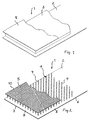
- the cover sheet 1 shown in the figures is constructed in three layers. It has a plastic film on the bottom existing sealing membrane 2, on which a drainage layer 3 is applied. As can be seen from Figure 2, there is the drainage layer 3 out of a multitude of knobs 4 which are parallel protrude from the surface of the sealing membrane 2. This training has the advantage that the knobs 4 together with the sealing membrane 2 in one operation, for example can be made by injection molding.
- a filter layer consisting of a filter fleece 5 applied and connected to the drainage layer 3, namely by thermal treatment, which leads to a weld of the Contact points of the knobs 4 with the filter layer 5 out Has.
- the drainage layer 3 does not extend over the entire area the sealing membrane 2, but leaves on a long side 6 and a transverse side 7 each have an edge strip. Furthermore is the filter layer 5 in relation to the sealing membrane 2 offset that the sealing membrane 2 on the long side 6 and the transverse side 7 in the area of the knob-free edge areas Overlap areas 8, 9 forms that are free of drainage 3 and filter layer 5 are. Over these areas 8, 9, as shown in Figure 3, an overlap with neighboring Cover sheets 1 are produced.
Landscapes
- Engineering & Computer Science (AREA)
- Environmental & Geological Engineering (AREA)
- Life Sciences & Earth Sciences (AREA)
- Hydrology & Water Resources (AREA)
- General Life Sciences & Earth Sciences (AREA)
- Mining & Mineral Resources (AREA)
- Paleontology (AREA)
- Civil Engineering (AREA)
- General Engineering & Computer Science (AREA)
- Structural Engineering (AREA)
- Processing Of Solid Wastes (AREA)
- Separation Using Semi-Permeable Membranes (AREA)
- Filtering Materials (AREA)
- Sink And Installation For Waste Water (AREA)
Abstract
Die Erfindung betrifft eine Abdeckbahn (1) für Altlastenkörper, z. B. Müll- oder Kohlehalden oder dergleichen, mit einer auf einen Untergrund auflegbaren Dichtungsbahn (2), einer darauf angebrachten Drainagelage (3) und einer darauf verschiebefest vorgesehenen Filterschicht (5), die dadurch gekennzeichnet ist, daß die Drainagelage (3) durch eine Vielzahl von an der Oberseite der Dichtungsbahn (2) ausgebildeten Vorsprüngen (4) gebildet ist. <IMAGE>The invention relates to a cover sheet (1) for contaminated bodies, for. B. garbage or coal dumps or the like, with a sealing membrane (2) which can be placed on a substrate, a drainage layer (3) attached thereon and a filter layer (5) provided thereon which is displaceably provided, which is characterized in that the drainage layer (3) by a A plurality of projections (4) formed on the top of the sealing sheet (2) is formed. <IMAGE>
Description
Die Erfindung betrifft eine Abdeckbahn für Altlastenkörper, z. B. Müll- oder Kohlehalden oder dergleichen, mit einer auf einen Untergrund auflegbaren Dichtungsbahn, einer darauf angebrachten Drainagelage und einer darauf verschiebefest vorgesehenen Filterschicht.The invention relates to a cover sheet for contaminated bodies, for. B. garbage or coal dumps or the like, with one a waterproof membrane that can be placed on top, one attached to it Drainage layer and a slidably provided Filter layer.
Im Stand der Technik ist es bekannt, Altlastenkörper, insbesondere Müllhalden, obenseitig mit einer Abdeckbahn zu versehen, auf die dann Mutterboden mit Pflanzen in einer Höhe von 30 bis 200 cm aufgebracht wird. Aufgabe der Abdeckung ist es dabei, ein Eindringen von Oberflächensickerwasser in den Altlastenkörper einerseits und unkontrollierte Emissionen aus dem Deponiekörper in den Boden und in die Atmosphäre andererseits zu vernindern.In the prior art it is known to contaminate contaminated sites, in particular Garbage dumps, to be provided with a cover sheet on the top, on the then topsoil with plants at a height of 30 to 200 cm is applied. The task of the cover is penetration of surface leachate into the contaminated site on the one hand and uncontrolled emissions from the landfill body into the ground and into the atmosphere on the other hand deny.
Aus der DE-PS 34 44 895 ist es bekannt, die Abdeckbahn aus Sandwichplatten auszubilden, die jeweils eine untenliegende Dichtungsschicht, eine darüberliegende Drainageschicht und eine darauf liegende Filterschicht aus Vliesmaterial aufweisen. Das Sickerwasser, das von der Oberfläche der Deponieabdekung in den Wurzelboden eindringt, wird dabei von der Dichtungsschicht zurückgehalten und in der darüberliegenden Drainageschicht, die in Form eines Gitters ausgebildet ist, abgeführt. Die Filterschicht hat die Aufgabe, das Eindringen von feinen Bodenteilchen in die Drainageschicht zu verhindern.From DE-PS 34 44 895 it is known that the cover sheet Form sandwich panels, each one below Sealing layer, an overlying drainage layer and have a filter layer of nonwoven material lying thereon. The leachate from the surface of the landfill cover penetrates into the root soil, is thereby from the sealing layer retained and in the overlying drainage layer, which is designed in the form of a grid. The filter layer has the task of penetrating fine To prevent soil particles in the drainage layer.
Mit der bekannten Abdeckbahn ist zwar eine zufriedenstellende Abdichtung möglich, jedoch ist sie aufwendig in der Herstellung, da die einzelnen Schichten getrennt voneinander hergestellt und dann miteinander verklebt oder verschweißt werden müssen.With the known cover sheet is a satisfactory one Sealing possible, but it is complex to manufacture, because the individual layers are made separately and then glued or welded together have to.
Der Erfindung liegt daher die Aufgabe zugrunde, eine Abdeckbahn der eingangs genannten Art so zu gestalten, daß sie einfach und günstig in der Herstellung ist.The invention is therefore based on the object of a cover sheet of the type mentioned in such a way that they are simple and is inexpensive to manufacture.
Diese Aufgabe wird erfindungsgemäß dadurch gelöst, daß die Drainagelage durch eine Vielzahl von an der Oberseite der Dichtungsbahn ausgebildeten Vorsprüngen gebildet ist. Durch diese einstückige Ausbildung der Drainagelage in Form von Vorsprüngen an der Dichtungsbahn wird erreicht, daß Dichtungsbahn und Drainagelage in einem Arbeitsgang beispielsweise durch Spritzguß zusammen hergestellt werden können. Hierdurch wird die Herstellung im Vergleich zu den bekannten Abdeckbahnen, bei denen die einzelnen Schichten getrennt voneinander hergestellt und dann miteinander verschweißt werden müssen, deutlich vereinfacht.This object is achieved in that the Drainage through a variety of on top of the waterproofing membrane trained projections is formed. Through this one-piece formation of the drainage layer in the form of projections on the geomembrane is achieved that geomembrane and Drainage in one operation, for example by injection molding can be made together. This will manufacture compared to the known cover sheets, in which the individual layers are produced separately and then have to be welded together, significantly simplified.
Die Vorsprünge haben vorzugsweise eine einfache Gestalt, beispielsweise Noppenform, wobei sie so ausgestaltet sein müssen, daß sie bei gewünschter Dicke der Drainagelage von beispielsweise 5 bis 25 mm eine ausreichende Festigkeit haben und insbesondere nicht knicken.The protrusions are preferably simple in shape, for example Knob shape, whereby they must be designed that at the desired thickness of the drainage layer, for example 5 to 25 mm have sufficient strength and in particular Do not bend.
Als Materialien für die Dichtungsbahn kommen Polyethylen, Polyvinylchlorid, Polypropylen, ECB und Ethylen/Vinylacetet-Copolymere in Frage. Für den Trennkörper können Polypropylen, Polyethylen und Polyamid verwendet werden. Als Material für das Filtervlies kommen Polypropylen, Polyester und Polyethylen zur Anwendung.Polyethylene, polyvinyl chloride, Polypropylene, ECB and ethylene / vinyl acetate copolymers in question. Polypropylene, polyethylene can be used for the separating body and polyamide can be used. As material for that Filter fleece comes in polypropylene, polyester and polyethylene Application.
Für die Dichtungsbahn wird eine Dicke von 0,5 bis 4 mm vorgeschlagen. A thickness of 0.5 to 4 mm is proposed for the sealing membrane.
Die Filterschicht ist vorzugsweise als Filtervlies mit einem Flächengewicht von 70 bis 800 g/m2 ausgebildet. Auch hier sollten die Filterschicht und die Drainagelage durch thermische Verschmelzung oder Verklebung miteinander verbunden sein.The filter layer is preferably designed as a filter fleece with a basis weight of 70 to 800 g / m 2 . Here, too, the filter layer and the drainage layer should be connected to one another by thermal fusion or gluing.
Nach einem weiteren Merkmal der Erfindung ist vorgesehen, daß die Dichtungslage außenseitig aufgerauht ist, damit sie nicht gegenüber dem Untergrund, auf dem sie aufgelegt ist, verrutschen kann. Besonders vorteilhaft ist, die Aufrauhung mit Hilfe einer Profilierung vorzusehen, beispielsweise durch vorspringende Stege oder durch Nuten.According to a further feature of the invention it is provided that the sealing layer is roughened on the outside so that it does not slip against the surface on which it is placed can. It is particularly advantageous to roughen with the help to provide a profile, for example by projecting Webs or through grooves.
Die Erfindung sieht desweiteren vor, daß die Dichtungsbahn an einer Längs- und einer Querseite Überlappungsbereiche aufweist, welche über die Drainagelage und die Filterschicht vorstehen. Der Überstand dient dazu, eine Überlappung mit einer benachbarten Abdeckbahn herzustellen und so eine gasdichte Abdichtung zu ermöglichen. Auf diese Weise kann die gesamte Abdeckung flüssigkeitsdicht gestaltet werden.The invention further provides that the sealing membrane one longitudinal and one transverse side has overlapping areas, which protrude above the drainage layer and the filter layer. The protrusion serves to overlap with a neighboring cover sheet and create a gas-tight seal to enable. This way the entire coverage be made liquid-tight.
Desweiteren ist vorgeschlagen, daß die Drainagelage und die Filterschicht an einer Längs- und einer Querseite über die Dichtungsbahn vorstehen, um auch insoweit eine Überlappung mit benachbarten Abdeckbahnen zu ermöglichen. Vorzugsweise sollte dabei die Filterschicht an einer Längs- und einer Querseite über die Drainagelage vorstehende Überlappungsbereiche bilden, so daß die Filterschichten nicht nur aneinanderstoßen, sondern auch überlappen.Furthermore, it is proposed that the drainage layer and the Filter layer on one long and one short side over the Protect geomembrane in order to have an overlap to enable neighboring cover sheets. Preferably should the filter layer on one long and one short side form protruding overlap areas over the drainage layer, so that the filter layers not only meet, but also overlap.
In der Zeichnung ist die Erfindung anhand eines Ausführungsbeispiels näher veranschaulicht. Es zeigen:
- Figur 1
- das Ende einer Abdeckbahn in Schrägansicht und schematisch dargestellt,
Figur 2- die Abdeckbahn gemäß Figur 1 in detaillierterer Darstellung und
Figur 3- in geschnittener Seitenansicht zwei sich teilweise überlappende Abdeckbahnen.
- Figure 1
- the end of a cover sheet shown diagonally and schematically,
- Figure 2
- the cover sheet of Figure 1 in more detail and
- Figure 3
- in a sectional side view two partially overlapping cover sheets.
Die in den Figuren dargestellte Abdeckbahn 1 ist dreilagig aufgebaut.
Sie hat an der Unterseite eine aus einer Kunststofffolie
bestehende Dichtungsbahn 2, auf die eine Drainagelage 3
aufgebracht ist. Wie aus Figur 2 zu ersehen, besteht die Drainagelage
3 aus aus einer Vielzahl von Noppen 4, die parallel
zueinander von der Oberfläche der Dichtungsbahn 2 vorstehen.
Diese Ausbildung hat den Vorteil, daß die Noppen 4 zusammen
mit der Dichtungsbahn 2 in einem Arbeitsgang beispielsweise
durch Spritzgießen hergestellt werden kann. Auf die Drainagelage
3 ist eine aus einem Filtervlies bestehende Filterschicht
5 aufgebracht und mit der Drainagelage 3 verbunden, und zwar
durch thermische Behandlung, die zu einer Verschweißung der
Kontaktstellen der Noppen 4 mit der Filterschicht 5 geführt
hat.The cover sheet 1 shown in the figures is constructed in three layers.
It has a plastic film on the bottom
existing
Die Drainagelage 3 erstreckt sich nicht über den gesamten Bereich
der Dichtungsbahn 2, sondern läßt an einer Längsseite 6
und einer Querseite 7 jeweils einen Randstreifen frei. Außerdem
ist die Filterschicht 5 derart gegenüber der Dichtungsbahn
2 versetzt angeordnet, daß die Dichtungsbahn 2 an der Längsseite
6 und der Querseite 7 im Bereich der noppenfreien Randbereiche
Überlappungsbereiche 8, 9 bildet, die frei von Drainagelage
3 und Filterschicht 5 sind. Über diese Bereiche 8, 9 kann,
wie in Figur 3 dargestellt ist, eine Überlappung mit benachbarten
Abdeckbahnen 1 hergestellt werden.The
Da die Filterschicht 5 die gleichen Abmessungen wie die Dichtungsbahn
2 hat, hat die vorgenannte Versetzung von Dichtungsbahn
2 und Filterschicht 5 zur Folge, daß die Filterschicht 5
an den den Überlappungsbereichen 8, 9 gegenüberliegenden Seiten
Überlappungsbereiche 10 bildet, die frei von Filterschicht
5 und Drainagelage 3 sind, und über die ebenfalls eine Überlappung
mit den benachbarten Abdeckbahnen hergestellt werden
kann.Since the
Claims (13)
dadurch gekennzeichnet, daß die Drainagelage (3) durch eine Vielzahl von an der Oberseite der Dichtungsbahn (2) ausgebildeten Vorsprüngen (4) gebildet ist.Cover sheet (1) for contaminated bodies, e.g. B. garbage or coal dumps or the like, with a sealing membrane (2) which can be placed on a substrate, a drainage layer (3) attached thereon and a filter layer (5) provided thereon so as to be displaceable,
characterized in that the drainage layer (3) is formed by a plurality of projections (4) formed on the upper side of the sealing membrane (2).
dadurch gekennzeichnet, daß die Vorsprünge (4) noppenartig ausgebildet sind.Cover sheet according to claim 1,
characterized in that the projections (4) are nub-like.
dadurch gekennzeichnet, daß die Dichtungsbahn (2) mit den Vorsprüngen (4) durch Spritzguß hergestellt ist.Cover sheet according to claim 1 or 2,
characterized in that the sealing membrane (2) with the projections (4) is produced by injection molding.
dadurch gekennzeichnet, daß die Drainagelage (3) eine Dicke von 5 bis 25 mm hat.Covering sheet according to one of the preceding claims,
characterized in that the drainage layer (3) has a thickness of 5 to 25 mm.
dadurch gekennzeichnet, daß die Dichtungsbahn (2) aus einer Kunststoffolie besteht.Covering sheet according to one of the preceding claims,
characterized in that the sealing membrane (2) consists of a plastic film.
dadurch gekennzeichnet, daß die Dichtungsbahn (2) eine Dicke von 0,5 bis 4 mm hat.Cover sheet according to claim 5,
characterized in that the sealing membrane (2) has a thickness of 0.5 to 4 mm.
dadurch gekennzeichnet, daß die Filterschicht als Filtervlies (5) ausgebildet ist.Covering sheet according to one of claims 1 to 6,
characterized in that the filter layer is designed as a filter fleece (5).
dadurch gekennzeichnet, daß das Filtervlies (5) ein Flächengewicht von 70 bis 800 g/m2 hat.Cover sheet according to claim 7,
characterized in that the filter fleece (5) has a basis weight of 70 to 800 g / m 2 .
dadurch gekennzeichnet, daß die Filterschicht (5) und die Drainagelage (3) durch thermische Verschmelzung miteinander verbunden sind.Covering sheet according to one of claims 1 to 8,
characterized in that the filter layer (5) and the drainage layer (3) are connected to one another by thermal fusion.
dadurch gekennzeichnet, daß die Dichtungsbahn (2) außenseitig aufgerauht ist.Covering sheet according to one of claims 1 to 9,
characterized in that the sealing membrane (2) is roughened on the outside.
dadurch gekennzeichnet, daß die Dichtungsbahn (2) außenseitig mit einer Profilierung versehen ist.Cover sheet according to claim 10,
characterized in that the sealing membrane (2) is provided on the outside with a profile.
dadurch gekennzeichnet, daß die Dichtungsbahn (2) an einer Längs- und einer Querseite (6, 7) Überlappungsbereiche (8, 9) aufweist, welche über die Drainagelage (3) und die Filterschicht (5) vorstehen.Covering sheet according to one of claims 1 to 11,
characterized in that the sealing membrane (2) has overlap areas (8, 9) on one longitudinal and one transverse side (6, 7) which project beyond the drainage layer (3) and the filter layer (5).
dadurch gekennzeichnet, daß die Filterschicht (5) an einer Längs- und einer Querseite über die Dichtungsbahn (2) vorstehende Überlappungsbereiche (10) aufweist.Covering sheet according to one of claims 1 to 12,
characterized in that the filter layer (5) has overlap areas (10) projecting over the sealing membrane (2) on one longitudinal and one transverse side.
Applications Claiming Priority (2)
| Application Number | Priority Date | Filing Date | Title |
|---|---|---|---|
| DE19627709 | 1996-07-10 | ||
| DE19627709 | 1996-07-10 |
Publications (2)
| Publication Number | Publication Date |
|---|---|
| EP0818580A2 true EP0818580A2 (en) | 1998-01-14 |
| EP0818580A3 EP0818580A3 (en) | 1998-10-28 |
Family
ID=7799387
Family Applications (2)
| Application Number | Title | Priority Date | Filing Date |
|---|---|---|---|
| EP19970111785 Withdrawn EP0818580A3 (en) | 1996-07-10 | 1997-07-10 | Cover sheet for waste dumps |
| EP19970111784 Withdrawn EP0818579A3 (en) | 1996-07-10 | 1997-07-10 | Method for covering waste dumps |
Family Applications After (1)
| Application Number | Title | Priority Date | Filing Date |
|---|---|---|---|
| EP19970111784 Withdrawn EP0818579A3 (en) | 1996-07-10 | 1997-07-10 | Method for covering waste dumps |
Country Status (1)
| Country | Link |
|---|---|
| EP (2) | EP0818580A3 (en) |
Families Citing this family (1)
| Publication number | Priority date | Publication date | Assignee | Title |
|---|---|---|---|---|
| DE10138539B4 (en) * | 2001-02-20 | 2007-02-01 | Universität Kassel-Witzenhausen (GhK) Fachgebiet Abfallwirtschaft und Altlasten | Device for surface sealing, in particular of landfills |
Citations (7)
| Publication number | Priority date | Publication date | Assignee | Title |
|---|---|---|---|---|
| DE3127265A1 (en) * | 1981-07-10 | 1983-01-27 | Ewald Dörken GmbH & Co KG, 5804 Herdecke | COMPONENT WITH PROTECTIVE AND DRAINAGE EFFECT |
| EP0259165A2 (en) * | 1986-09-05 | 1988-03-09 | Leucadia Inc | Subsurface drainage matting |
| DE8902963U1 (en) * | 1989-03-10 | 1990-07-12 | Niederberg-Chemie Gmbh, 4133 Neukirchen-Vluyn, De | |
| US4943185A (en) * | 1989-03-03 | 1990-07-24 | Mcguckin James P | Combined drainage and waterproofing panel system for subterranean walls |
| US5258217A (en) * | 1991-05-28 | 1993-11-02 | A/A Manufacturing, Inc. | Landfill liner |
| GB2293851A (en) * | 1994-10-05 | 1996-04-10 | Prestige Air Technology Limite | Gas dispersal and collection |
| DE19518602A1 (en) * | 1995-05-23 | 1996-11-28 | Stein Cadenbach Bernd | Sealing film for flat roof grassing or tip and tunnel areas |
Family Cites Families (4)
| Publication number | Priority date | Publication date | Assignee | Title |
|---|---|---|---|---|
| GB2141732B (en) * | 1983-06-03 | 1986-11-12 | Summerleaze Gravel Co Ltd The | Method and apparatus for gas production |
| DE3703442A1 (en) * | 1987-02-05 | 1990-04-19 | Richter Hans | Promoting bacteriological break-down of tipped wastes - by applying treated water under covering plastic sheet |
| BE1009209A3 (en) * | 1995-03-14 | 1996-12-03 | Pharo Ltd | LIQUID RESISTANT covering. |
| KR950031495A (en) * | 1994-04-05 | 1995-12-18 | 엘.제이.윌리스 | Liquid repellent coating layer and preparation method thereof |
-
1997
- 1997-07-10 EP EP19970111785 patent/EP0818580A3/en not_active Withdrawn
- 1997-07-10 EP EP19970111784 patent/EP0818579A3/en not_active Withdrawn
Patent Citations (7)
| Publication number | Priority date | Publication date | Assignee | Title |
|---|---|---|---|---|
| DE3127265A1 (en) * | 1981-07-10 | 1983-01-27 | Ewald Dörken GmbH & Co KG, 5804 Herdecke | COMPONENT WITH PROTECTIVE AND DRAINAGE EFFECT |
| EP0259165A2 (en) * | 1986-09-05 | 1988-03-09 | Leucadia Inc | Subsurface drainage matting |
| US4943185A (en) * | 1989-03-03 | 1990-07-24 | Mcguckin James P | Combined drainage and waterproofing panel system for subterranean walls |
| DE8902963U1 (en) * | 1989-03-10 | 1990-07-12 | Niederberg-Chemie Gmbh, 4133 Neukirchen-Vluyn, De | |
| US5258217A (en) * | 1991-05-28 | 1993-11-02 | A/A Manufacturing, Inc. | Landfill liner |
| GB2293851A (en) * | 1994-10-05 | 1996-04-10 | Prestige Air Technology Limite | Gas dispersal and collection |
| DE19518602A1 (en) * | 1995-05-23 | 1996-11-28 | Stein Cadenbach Bernd | Sealing film for flat roof grassing or tip and tunnel areas |
Also Published As
| Publication number | Publication date |
|---|---|
| EP0818580A3 (en) | 1998-10-28 |
| EP0818579A3 (en) | 1998-10-28 |
| EP0818579A2 (en) | 1998-01-14 |
Similar Documents
| Publication | Publication Date | Title |
|---|---|---|
| DE3444895C2 (en) | ||
| DE3642063C2 (en) | ||
| DE3432813C2 (en) | Laminated bituminous cover skin | |
| EP0536475B1 (en) | Waterimpervious liner to be used in civil engineering for the protection of soil from liquids | |
| DE2605552A1 (en) | SUCTIVE TEMPLATE | |
| EP0522546A1 (en) | Improved bonding of the overlapping areas of needle punched bentonite sealing liners | |
| EP0274564B1 (en) | Impervious barrier for creating new waste disposals | |
| DE2922993A1 (en) | DISPOSABLE HYGIENE ARTICLES WITH A LIQUID-PERMEABLE SURFACE LAYER | |
| DE8215946U1 (en) | SEALING STRIP | |
| EP0450154B1 (en) | Use of a protecting element for the protection of sealing layers in landfills, and a method for sealing landfills. | |
| DE4022338C2 (en) | ||
| EP0818580A2 (en) | Cover sheet for waste dumps | |
| EP0193605B2 (en) | Foil material for controllable leakproof separation of the areas located on both of its sides | |
| DE4131391A1 (en) | Sealing system for steeply sloping dumps - has inner sealing membrane with reinforcements and special surface texture, drainage layer, and outermost covering of suitable material | |
| DE3811487A1 (en) | Installation and method for dumping and storing waste, refuse and the like | |
| DE4400183A1 (en) | Hexagonal drainage elements assembled as drainage lining for open refuse tip | |
| DE60310403T2 (en) | METHOD FOR PRODUCING A WATERPROOFING MATERIAL | |
| DE2054029C3 (en) | Plastic waterproofing membrane | |
| EP0947312A2 (en) | Structural member | |
| DE8109869U1 (en) | "ROOF COVER WITH VAPOR RELAXATION LAYER" | |
| DE2560210C2 (en) | Sealing skin on a supporting structure, e.g. a drinking water tank made of weldable and flexible sheets | |
| DE4109050C2 (en) | Barrier drainage mat | |
| AT398284B (en) | METHOD FOR PRODUCING A SEALING MAT, AND SEALING MAT PRODUCED BY THIS PROCESS | |
| LU102957B1 (en) | Molded part for building sealing | |
| DE3638233C2 (en) |
Legal Events
| Date | Code | Title | Description |
|---|---|---|---|
| PUAI | Public reference made under article 153(3) epc to a published international application that has entered the european phase |
Free format text: ORIGINAL CODE: 0009012 |
|
| AK | Designated contracting states |
Kind code of ref document: A2 Designated state(s): AT BE CH DE DK ES FI FR GB GR IE IT LI LU MC NL PT SE |
|
| PUAL | Search report despatched |
Free format text: ORIGINAL CODE: 0009013 |
|
| AK | Designated contracting states |
Kind code of ref document: A3 Designated state(s): AT BE CH DE DK ES FI FR GB GR IE IT LI LU MC NL PT SE |
|
| AKX | Designation fees paid | ||
| STAA | Information on the status of an ep patent application or granted ep patent |
Free format text: STATUS: THE APPLICATION IS DEEMED TO BE WITHDRAWN |
|
| 18D | Application deemed to be withdrawn |
Effective date: 19990429 |
|
| REG | Reference to a national code |
Ref country code: DE Ref legal event code: 8566 |