EP0818161A1 - Display shelf - Google Patents
Display shelf Download PDFInfo
- Publication number
- EP0818161A1 EP0818161A1 EP97111250A EP97111250A EP0818161A1 EP 0818161 A1 EP0818161 A1 EP 0818161A1 EP 97111250 A EP97111250 A EP 97111250A EP 97111250 A EP97111250 A EP 97111250A EP 0818161 A1 EP0818161 A1 EP 0818161A1
- Authority
- EP
- European Patent Office
- Prior art keywords
- display unit
- unit according
- tubular element
- outer tubular
- upright
- Prior art date
- Legal status (The legal status is an assumption and is not a legal conclusion. Google has not performed a legal analysis and makes no representation as to the accuracy of the status listed.)
- Ceased
Links
Images


Classifications
-
- A—HUMAN NECESSITIES
- A47—FURNITURE; DOMESTIC ARTICLES OR APPLIANCES; COFFEE MILLS; SPICE MILLS; SUCTION CLEANERS IN GENERAL
- A47B—TABLES; DESKS; OFFICE FURNITURE; CABINETS; DRAWERS; GENERAL DETAILS OF FURNITURE
- A47B87/00—Sectional furniture, i.e. combinations of complete furniture units, e.g. assemblies of furniture units of the same kind such as linkable cabinets, tables, racks or shelf units
- A47B87/02—Sectional furniture, i.e. combinations of complete furniture units, e.g. assemblies of furniture units of the same kind such as linkable cabinets, tables, racks or shelf units stackable ; stackable and linkable
- A47B87/0207—Stackable racks, trays or shelf units
- A47B87/0215—Stackable frames, or frame elements, with upright parts connected by inserting the ends or tips of the uprights, e.g. at the corners, into the uprights of the next frame or frame element, e.g. coaxial tubular ends
-
- A—HUMAN NECESSITIES
- A47—FURNITURE; DOMESTIC ARTICLES OR APPLIANCES; COFFEE MILLS; SPICE MILLS; SUCTION CLEANERS IN GENERAL
- A47F—SPECIAL FURNITURE, FITTINGS, OR ACCESSORIES FOR SHOPS, STOREHOUSES, BARS, RESTAURANTS OR THE LIKE; PAYING COUNTERS
- A47F5/00—Show stands, hangers, or shelves characterised by their constructional features
- A47F5/10—Adjustable or foldable or dismountable display stands
- A47F5/11—Adjustable or foldable or dismountable display stands made of cardboard, paper or the like
- A47F5/112—Adjustable or foldable or dismountable display stands made of cardboard, paper or the like hand-folded from sheet material
- A47F5/116—Shelving racks
Definitions
- the present invention relates to display units with shelves.
- the display units concerned are usable, for example, for displaying products such as food products at points of sale such as shops, supermarkets, hypermarkets, etc.
- the relevant state of the art is extremely abundant and extensive as shown, for example, by United States patents 1 444 268 and 1 930 787, as well as 2 689 050, and by German application 21 31 870 and by Swiss patents 281 702 and 498 605, to mention only a few background examples.
- the present invention relates to a display unit with shelves according to the preamble to Claim 1 which is known, for example, from US-A-4 050 386.
- This prior document describes a display unit comprising a plurality of polygonal, typically rectangular, shelves made of sheet material, supported at their corners by uprights having L-shaped cross-sections. Each upright is constituted by a plurality of adjoining sections which can be coupled in a generally male-and-female configuration (more precisely, in the configuration generally known as a "mortice-and-tenon" configuration).
- the same document describes the possibility of producing the uprights by bending from a composite wood or cardboard panel possibly having a covering of flexible, decorative material such as polyvinyl chloride or other plastics materials.
- the object of the present invention is to provide a display unit of the type specified above which can be produced almost exclusively from bent cardboard elements.
- the display unit can consequently be produced in the form of one or more precut and punched cardboard blanks which can be stored and transported to the place of use in the form of a generally flat body.
- the various parts of the display unit can thus be formed by bending operations and the display unit can then be erected in the place of use by the assembly of the parts thus obtained.
- the object of the present invention is therefore to provide a solution which, on the one hand, satisfies the requirements outlined above and, on the other hand, avoids the problems stressed above.
- this object is achieved by means of a display unit with shelves having the further characteristics recited in Claim 1.
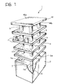
- a display unit with shelves usable, for example, for displaying food products (for example, confectionery products) in sales locations, such as shops, supermarkets, hypermarkets, etc., is generally indicated 1.
- the display unit 1 is formed entirely or mostly from elements of sheet material, typically cardboard, mostly produced initially in the form of flat blanks.
- the display unit 1 can therefore be stored (before and after use) and transported to and from the place of use in the form of a flattened body.
- the various component parts of the display unit which will be described further below, are formed by means of a bending and shaping operation in order to be connected to one another during the assembly of the display unit. After use, the unit can be dismantled if necessary and the respective parts spread out and flattened again for storage in the form of a flat body.
- the display unit 1 usually comprises, according to known criteria, a base 2 for bearing on the ground.
- One or more uprights 3 (four in the embodiment shown) extend upwardly from the base 2 in order to support a plurality of shelves 4; in the embodiment shown in Figure 1, the display unit 1 comprises four shelves 4 supported above the base 2 (the upper face 5 of which may also constitute a further shelf), plus a structurally similar element, indicated 40, which acts as a top surface or cover of the display unit 1.
- the element 40 may also hold further products (some of these are schematically indicated P and shown on one of the shelves 4) or may be used for supporting a decorative element (for example, a notice) fitted on top of the display unit 1 as a final touch.
- the shelves 4, as well as the top element 40 and the upper face 5 of the base 2 are rectangular and are interconnected by four uprights 3 situated in generally inner positions of the various elements 4, 40 and 5.
- the uprights 3 are situated at the corners of an imaginary rectangle having diagonals (or principal axes) coinciding with the diagonals (and the principal axes) of the rectangles defined by the various elements 4, 40 and 5 whilst having smaller dimensions than the latter rectangles.
- the base 2 (if present) is configured as a kind of box of sheet material produced (according to widely known criteria) in the form of a flat blank which, at the time of use, can be shaped so as to adopt a generally parallelepipedal shape closed at the top by the wall defining the face 5 in which there are respective holes 5a through which the uprights 3 can extend.
- the base 2 may be filled with a mass of expanded material (such as expanded polystyrene) with the function of strengthening and/or increasing weight.
- expanded material such as expanded polystyrene
- the box forming the base 2 may be at least partially filled with a material having a certain intrinsic weight, such as expanded clay, etc.
- the shelves 4 are preferably configured in the form of flat trays each having a base 4a in which there are respective holes 4b through which the uprights 3 can extend. Further holes such as those schematically indicated 0 solely in Figure 1 may also be provided, defining seats for housing respective products.
- the shelves 4 may be generally flat or, as shown in the drawings, may have portions 4c turned up or down along their peripheries and extending perpendicularly to the base 4a (or in any case deviating therefrom). This preferably has the function of stiffening the base 4a structurally. In particular, in the embodiment (and assembly) shown in Figures 1 and 2, the portion 4c is turned upwardly and can thus act as a wall for containing products P on the shelf 4.
- the element in question is composed precisely of a flat portion 40a surrounded by a downwardly-turned skirt portion 40b.
- the uprights 3 are constituted by a series of adjoining elements coupled to one another (according to general "mortice-and-tenon"-like coupling criteria). This result is achieved by the production of the uprights 3 in the form of adjoining modules defining an alternating sequence of tubular elements indicated 31 (outer elements) and 32 (inner elements), respectively.
- each element 32 is formed by a rectangular blank of sheet material (for example cardboard) in which four bend lines perpendicular to the longer sides of the blank (and hence parallel to the shorter sides of the blank) are formed, spaced apart by almost identical distances.
- sheet material for example cardboard
- the blank is thus divided into five approximately identical strips and can be bent (rolled up) into a tube, forming a tubular body with a square cross-section; three walls of this body are constituted by three of the aforementioned five strips (for precision, by the central strip and by the two strips adjacent thereto), whilst the fourth wall is constituted by the remaining two of the aforesaid strips (for precision, the end strips) which overlap, as schematically indicated 331, 332 in Figure 3.
- the element 32 is formed in a manner such that its sides have dimensions exactly corresponding (except for the minimal tolerance which is, of course, necessary) to the dimensions of the holes 4b formed in the shelves 4 and the holes 5a in the upper face 5 of the base 2.
- the solution described for the formation of the elements 32 is preferred, it should not be considered essential.
- the elements are formed starting with a flat, approximately rectangular blank in which four bend lines are formed (perpendicular to the longer sides and parallel to the shorter sides) so as to create five strips indicated in order 310 to 314.
- the last strip which is to be folded onto the first strip 310 when the blank in question is closed to form a tube, as shown in Figure 3, generally has smaller dimensions than the other strips.
- the dimensions of the blank shown in Figure 5 and the positions of the bend lines which create the various strips 310 to 314 are selected in a manner such that, once it has been bent to form a tube as shown in Figure 3, the internal cavity of the element 31 has dimensions such that an element 32 of the type described above can be housed for sliding within it (preferably without giving rise to appreciable play or interference).
- the square cross-section illustrated with reference to the element 32 is not essential (to give only one example, a triangular shape would be possible).
- the same reasoning thus also applies to the elements 31 which, in general, should have a shape complementary to that of the elements 32 so that they can be coupled in a continuously extending arrangement.
- the closure of the elements 31 as tubes is usually strengthened by fixing the strip 314 to the strip 310 in some way.
- This fixing may take place, for example, by adhesive means which may already be provided on the blank (for example, in the form of adhesive lines covered by strips for subsequent removal) or by the interposition of fasteners, etc.
- the female element 31 of the element shown in continuous outline in Figure 4 can house, in its lower end, the male element 32 of an identical module (also shown in broken outline) placed in position within the structure of each upright 3.
- the modular structure described permits the formation of successive sections of upright between which the shelves 4 of the display unit are interposed; in this connection, it should be noted, as already stated above, that the holes 4b in the shelves (and the holes 5a in the base 2) have dimensions approximately corresponding to the external dimensions of the elements 32.
- each upright 3 thus formed has excellent and uniform characteristics of stiffness (in the sense of resistance to bending relative to its axis). This is also achieved by a reduction in the overall length of the elements 32 so that it corresponds to only a fraction, which may be quite small, of the overall length (height) of the upright, with the elements 32 spaced apart, preferably with uniform spacing, within the respective upright 3. For this purpose, it is important to be able to regulate the extent or distance to which the element 32 penetrates the element 31 housing it, in all of the modules composed of an element 31 housing an element 32.
- two C-shaped incisions 315 are formed in at least one of two strips which are to define two of the faces of the element 31 (for example, in the two strips 311 and 313, in the solution to which Figure 5 relates), the concave sides of the incisions 315 facing away from the end of the element 31 which is to house the element 32.
- the portion of the strip which is surrounded by the incision 315 can thus be bent inwardly relative to the element 31 so as to create (again see Figures 3 and 4) a tab projecting like a bracket into the element 31.
- a stop or abutment element, indicated 316 is thus formed and interferes with the path of the penetration of the element 32 into the element 31 (see Figure 4 in this connection) so as to regulate precisely the extent of its travel.
- the operation to form the incision 315 is preferably repeated on two of the strips (the strips 311 and 313 in the embodiment shown) which are to form opposite faces of the element 31 so as to achieve the aforementioned resistance to the penetration of the element 32 symmetrically in diametrally-opposed positions relative to the development of the element 31.
- the elements 32 are thus spaced apart in each assembled upright 3.
- Two further tabs, indicated 317, project from the strips 311, 313 at the end of the element 31 in which the element 32 is engaged. This is the end at which a respective shelf 4 is intended to bear on the element 31 (see in particular Figure 4).
- any number of tabs 317 that is, a number equal to the number of faces of the element 32, or a smaller or larger number could be provided (for example, by the imaginary division of a single tab into separate tabs).
- the location of the tabs 317 on the same faces in which the notches 315 are formed corresponds to a constructionally practical selection but does not constitute an absolute requirement.
- top element 40 this may simply bear on the upper ends of the uprights 3 formed by elements 31 without corresponding elements 32 mounted inside them, or may have a box-like structure substantially similar to that of the base 2 with holes for housing elements 32 situated at the tops of the uprights.
- the base 2 may have inside it, extending vertically beneath the holes 5a, respective elements 31 structurally similar to the elements 31 shown in Figures 3 and 5 except for, preferably, a greater axial length. This is to take account of the fact that the height of the base 2 is preferably greater than the distance (identified by the heights of the elements 31) separating the shelves vertically.
- the structure of the uprights 3 which are constituted by respective outer and inner cylindrical, tubular elements 31 and 32.
- the elements 31 and 32 are of a cylindrical shape and can easily be formed, for example, with paper or cardboard, by the techniques currently used for producing cardboard tubes used as cores for rolls of fabric, wallpaper and paper for other uses, film for preserving food products, adhesive tapes, etc.
- the above-described male-and-female (mortice-and-tenon) coupling remains unchanged and may be formed with the male portions of the various upright sections projecting upwards or, preferably, (for reasons which will become clearer from the following) downwards.
- the inside diameter of the elements 31 and the outside diameter of the elements 32 are selected so as to give rise to a shaped coupling which is tight enough to prevent undesired relative movements whilst also avoiding too tight a fit such as to hinder the disconnection of the adjacent sections of each upright 3 when it is dismantled.
- Each element 32 can easily be fixed inside the respective element 31 of which the element 32 constitutes the upwardly-or downwardly-projecting tenon, for example, by gluing.
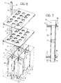
- the same drawing shows how the shelves 4 are held in the desired position because they are gripped, in the region of the holes 4b aligned with each upright 3, between two adjacent elements 31 belonging to two successive sections of the upright 3 concerned.
- the shelves 4 are produced in the form of double-layered panels, for example, of corrugated cardboard or a similar product, with the aforementioned adjacent elements 31 exerting their gripping action on one of the layers (usually that which is in the upper position in use) of the double-layered panel. It has been found that the structure described above can ensure excellent structural strength, even with a considerable number of holes or openings O, particularly with shelves formed by two layers of cardboard glued together.
- FIG. 6 shows how, with a solution which, moreover, can also be used in the embodiment shown in Figures 1 to 5, the downward projection of the tenons (the elements 32) associated with the lower sections of each upright 3 can be used to anchor the uprights 3 to the base 2.
- the base 2 has an internal reinforcing framework comprising a set of walls made of cardboard (or similar sheet material) arranged in two perpendicular rows 60, 61.
- Each row comprises two walls (but the number could be different, for example, larger) with cross-like intersections, particularly with intersection points - of which there are four in the embodiment shown located in the regions of the uprights 3.
- An arrangement of walls of this type can easily be produced by criteria widely known in the paper and cardboard industry, for example, by the provision of upwardly- or downwardly-facing vertical slots in the regions of the walls of each row corresponding to the walls of the other row.
- the walls of one row which have complementary vertical slots at the points of intersection, and hence slots facing downwardly or upwardly, in the opposite direction to the slots provided at the points of intersection in the wall of the other row, are slid into these slots.
- U-shaped slots or notches
- These slots or notches have a width and a length (depth) corresponding to the diameter and to the length (or height) of the elements 32 projecting downwardly from the uprights 3.
- the slots or notches 70 thus define respective seats for the engagement of the aforesaid elements which can be fitted firmly in the base 2 in the seats defined by the U-shaped slots or notches 70.
- Each of the aforesaid U-shaped slots or notches preferably has an appendage or tab 71 projecting upwardly in its base so as to be able to penetrate the axial cavity of the aforesaid tenon, fixing it more firmly in its engagement position.
- Figure 6 also shows that the walls 60, 61 of the reinforcing framework of the base 2 may have lower appendages 80, 81, preferably at intersection points (advantageously but not necessarily in alignment with the uprights 3) .
- These appendages which preferably have a cross-like structure, form respective feet for supporting the base 2, or reinforcing elements for shaped (for example mushroom-shaped and hollow) feet F associated with the base 2.
Landscapes
- Display Racks (AREA)
- Assembled Shelves (AREA)
Abstract
Description
- the presence of the
base 2 and/or of thetop element 40, - the number of
shelves 4, - the rectangular shape of the
shelves 4, as well as of thebase 2 and of theelement 40, - the presence of four
uprights 3, and - the location of the
uprights 3 in inner positions of one or more of the elements connected by theuprights 3, and not at the corners,
- an end (the lower end in Figure 5) constituting a female element (a mortice) and
- an opposite end (the upper end in Figure 4) acting as a
male element (a tenon) which can fit in the
female element 31 of an module disposed above it (shown in broken outline).
Claims (32)
Applications Claiming Priority (2)
| Application Number | Priority Date | Filing Date | Title |
|---|---|---|---|
| CH169196A CH691657A5 (en) | 1996-07-08 | 1996-07-08 | Display racks. |
| CH1691/96 | 1996-07-08 |
Publications (1)
| Publication Number | Publication Date |
|---|---|
| EP0818161A1 true EP0818161A1 (en) | 1998-01-14 |
Family
ID=4216359
Family Applications (1)
| Application Number | Title | Priority Date | Filing Date |
|---|---|---|---|
| EP97111250A Ceased EP0818161A1 (en) | 1996-07-08 | 1997-07-04 | Display shelf |
Country Status (2)
| Country | Link |
|---|---|
| EP (1) | EP0818161A1 (en) |
| CH (1) | CH691657A5 (en) |
Cited By (7)
| Publication number | Priority date | Publication date | Assignee | Title |
|---|---|---|---|---|
| EP0947150A1 (en) * | 1998-02-25 | 1999-10-06 | Steelcase Strafor | Multi-functional planar part used as a base and top for a mobile storage unit |
| AT3717U3 (en) * | 2000-04-14 | 2001-02-26 | Walter Pindur Ges M B H & Co K | SALES STAND |
| EP1838596A4 (en) * | 2005-01-19 | 2009-08-05 | Sonoco Dev Inc | Post in post product packaging and display structure |
| ITTO20120998A1 (en) * | 2012-11-16 | 2014-05-17 | Soremartec Sa | EXHIBITOR OF SWEET PRODUCTS WITH SURPRISE INSIDE |
| ITTO20130201A1 (en) * | 2013-03-15 | 2014-09-16 | Soremartec Sa | EXHIBITOR SHELVES OF SWEET PRODUCTS WITH SURPRISE INSIDE, IN PARTICULAR PASQUAL EGGS |
| CN110403378A (en) * | 2019-08-02 | 2019-11-05 | 胡建东 | A kind of bearing frame |
| KR20210076359A (en) * | 2019-12-16 | 2021-06-24 | (주)휘플 | Modular assembly furniture and its assembly method |
Citations (4)
| Publication number | Priority date | Publication date | Assignee | Title |
|---|---|---|---|---|
| CH490833A (en) * | 1968-05-14 | 1970-05-31 | Ed Mueller Hermann | Support column |
| DE3418602A1 (en) * | 1984-05-18 | 1985-11-21 | Schröter + Bake GmbH + Co KG Werke für moderne Verpackung, 8402 Neutraubling | Connection of tubular support elements made of cardboard or the like, in particular for sales stands |
| US4638745A (en) * | 1985-11-12 | 1987-01-27 | Merchandising Innovations, Inc. | Telescoping display stand |
| DE29614339U1 (en) * | 1996-08-07 | 1996-10-10 | Schwerdtle & Schantz GmbH, 12359 Berlin | Shelf system |
-
1996
- 1996-07-08 CH CH169196A patent/CH691657A5/en not_active IP Right Cessation
-
1997
- 1997-07-04 EP EP97111250A patent/EP0818161A1/en not_active Ceased
Patent Citations (4)
| Publication number | Priority date | Publication date | Assignee | Title |
|---|---|---|---|---|
| CH490833A (en) * | 1968-05-14 | 1970-05-31 | Ed Mueller Hermann | Support column |
| DE3418602A1 (en) * | 1984-05-18 | 1985-11-21 | Schröter + Bake GmbH + Co KG Werke für moderne Verpackung, 8402 Neutraubling | Connection of tubular support elements made of cardboard or the like, in particular for sales stands |
| US4638745A (en) * | 1985-11-12 | 1987-01-27 | Merchandising Innovations, Inc. | Telescoping display stand |
| DE29614339U1 (en) * | 1996-08-07 | 1996-10-10 | Schwerdtle & Schantz GmbH, 12359 Berlin | Shelf system |
Cited By (9)
| Publication number | Priority date | Publication date | Assignee | Title |
|---|---|---|---|---|
| EP0947150A1 (en) * | 1998-02-25 | 1999-10-06 | Steelcase Strafor | Multi-functional planar part used as a base and top for a mobile storage unit |
| AT3717U3 (en) * | 2000-04-14 | 2001-02-26 | Walter Pindur Ges M B H & Co K | SALES STAND |
| EP1838596A4 (en) * | 2005-01-19 | 2009-08-05 | Sonoco Dev Inc | Post in post product packaging and display structure |
| ITTO20120998A1 (en) * | 2012-11-16 | 2014-05-17 | Soremartec Sa | EXHIBITOR OF SWEET PRODUCTS WITH SURPRISE INSIDE |
| ITTO20130201A1 (en) * | 2013-03-15 | 2014-09-16 | Soremartec Sa | EXHIBITOR SHELVES OF SWEET PRODUCTS WITH SURPRISE INSIDE, IN PARTICULAR PASQUAL EGGS |
| EP2777440A1 (en) * | 2013-03-15 | 2014-09-17 | Soremartec S.A. | Shelf display unit |
| CN110403378A (en) * | 2019-08-02 | 2019-11-05 | 胡建东 | A kind of bearing frame |
| CN110403378B (en) * | 2019-08-02 | 2021-06-04 | 胡建东 | Bearing frame |
| KR20210076359A (en) * | 2019-12-16 | 2021-06-24 | (주)휘플 | Modular assembly furniture and its assembly method |
Also Published As
| Publication number | Publication date |
|---|---|
| CH691657A5 (en) | 2001-09-14 |
Similar Documents
| Publication | Publication Date | Title |
|---|---|---|
| US7066342B2 (en) | Modular packaging system for shipping and displaying palletized retail products | |
| US5125568A (en) | Stacking tray | |
| US5669683A (en) | Display shelf assembly | |
| CA2591263C (en) | Post in post product packaging and display structure | |
| US4911311A (en) | Display stand with vertically stacked trays | |
| US10278497B2 (en) | Display tray | |
| US4618115A (en) | Display device module with multiple shelves | |
| US6189778B1 (en) | Container with front pull-out panel | |
| US5704193A (en) | Container for shipping and displaying articles, and method for making | |
| US8602212B2 (en) | Stackable display container with box portion and reinforcing layer | |
| US6832562B2 (en) | Shipping container | |
| US20080264938A1 (en) | Container having sliding corner support | |
| US4706824A (en) | Variable sized free standing promotional display | |
| US6817514B2 (en) | Container having corner support | |
| US12408768B2 (en) | Modular greeting card rack | |
| EP2300325B1 (en) | Container | |
| US20100051568A1 (en) | Collapsible merchandising display | |
| US2980241A (en) | Box | |
| EP2711304A2 (en) | Display carton with controlled deflection zones | |
| US4273548A (en) | Method and device for folding blanks to form boxes | |
| US20060138206A1 (en) | Stackable container and container blank (L corner) | |
| CH691657A5 (en) | Display racks. | |
| US20060138205A1 (en) | Stackable container with air cell corner assembly and associated container blank | |
| US20060138204A1 (en) | Stackable container with angled corner panel and container blank | |
| WO2003086746A1 (en) | Composite structures |
Legal Events
| Date | Code | Title | Description |
|---|---|---|---|
| PUAI | Public reference made under article 153(3) epc to a published international application that has entered the european phase |
Free format text: ORIGINAL CODE: 0009012 |
|
| AK | Designated contracting states |
Kind code of ref document: A1 Designated state(s): AT BE CH DE DK ES FI FR GB GR IE IT LI LU MC NL PT SE |
|
| AX | Request for extension of the european patent |
Free format text: AL;LT;LV;RO;SI |
|
| 17P | Request for examination filed |
Effective date: 19980707 |
|
| AKX | Designation fees paid |
Free format text: AT BE CH DE DK ES FI FR GB GR IE IT LI LU MC NL PT SE |
|
| AXX | Extension fees paid |
Free format text: AL;LT;LV;RO;SI |
|
| RBV | Designated contracting states (corrected) |
Designated state(s): AT BE CH DE DK ES FI FR GB GR IE IT LI LU MC NL PT SE |
|
| 17Q | First examination report despatched |
Effective date: 19991007 |
|
| GRAG | Despatch of communication of intention to grant |
Free format text: ORIGINAL CODE: EPIDOS AGRA |
|
| STAA | Information on the status of an ep patent application or granted ep patent |
Free format text: STATUS: THE APPLICATION HAS BEEN REFUSED |
|
| 18R | Application refused |
Effective date: 20020510 |