EP0818090B1 - Verfahren und vorrichtung zum sicherstellen der anrufqualität in einem kommunikationssystem - Google Patents
Verfahren und vorrichtung zum sicherstellen der anrufqualität in einem kommunikationssystem Download PDFInfo
- Publication number
- EP0818090B1 EP0818090B1 EP96944761A EP96944761A EP0818090B1 EP 0818090 B1 EP0818090 B1 EP 0818090B1 EP 96944761 A EP96944761 A EP 96944761A EP 96944761 A EP96944761 A EP 96944761A EP 0818090 B1 EP0818090 B1 EP 0818090B1
- Authority
- EP
- European Patent Office
- Prior art keywords
- signal
- communication unit
- base site
- channel
- communication
- Prior art date
- Legal status (The legal status is an assumption and is not a legal conclusion. Google has not performed a legal analysis and makes no representation as to the accuracy of the status listed.)
- Expired - Lifetime
Links
Images


Classifications
-
- H—ELECTRICITY
- H04—ELECTRIC COMMUNICATION TECHNIQUE
- H04W—WIRELESS COMMUNICATION NETWORKS
- H04W36/00—Hand-off or reselection arrangements
- H04W36/24—Reselection being triggered by specific parameters
- H04W36/26—Reselection being triggered by specific parameters by agreed or negotiated communication parameters
Definitions
- the present invention relates generally to mitigating interference in a communication system and, in particular, to maintaining call quality in a communication system.
- GSM Global System for Mobile Communications
- a communication unit e.g., a mobile or portable radiotelephone
- a base site serving the coverage area in which the communication unit resides.
- the serving base site allocates a communication resource for the communication.
- the communication resource comprises a coordinated pair of time slots and frequencies (i.e., a first time slot at an uplink frequency and a second time slot at a downlink frequency).
- the time slot at the uplink frequency supports transmissions from the communication unit to the serving base site; whereas, the time slot at the downlink frequency supports transmissions from the serving base site to the communication unit.
- the base site Upon allocating the communication resource, the base site sends a channel designation signal to the communication unit via a common control channel.
- the channel designation signal contains the uplink time slot and frequency, the downlink time slot and frequency, and the transmit power for the communication unit.
- the communication unit Upon receiving the channel designation signal, the communication unit tunes its transmitter and receiver to the designated time slots and frequencies and begins communicating with a telephone network subscriber or another communication unit via the serving base site.
- the communication unit moves throughout the coverage area of the serving base site and the serving base site monitors a signal quality metric (e.g., received signal strength indication (RSSI)) of the communication unit's uplink communication signal.
- a signal quality metric e.g., received signal strength indication (RSSI)
- RSSI received signal strength indication
- the serving base site will issue commands directing the communication unit to increase or decrease the communication unit's transmit power as the need arises.
- the transmit power of the communication unit as well as the transmit power of the base site must be increased to account for an increase in path losses between the serving base site and the communication unit.
- This increased transmit power has the potential to interfere with an uplink/downlink communication signal at the same, or an adjacent, uplink/downlink frequency being used in another base site coverage area. That is, the higher power transmission of the communication unit and base site can increase the cochannel or adjacent channel interference in the other coverage area as viewed by the communication unit or base site serving that coverage area.
- a known technique for mitigating the increased cochannel and adjacent channel interference introduced by an interfering communication unit is to reassign, or hand-off, the communication unit that is being interfered with. This technique is described in detail in GSM Recommendation 05.08. Although this technique can adequately mitigate the effect of interference, the communication unit causing the interference will continue to be a potential interferer with any uplink/downlink communication signals at the same, or an adjacent, uplink/downlink frequencies assigned in other base site coverage areas.
- EP-A-0 530 165 discloses a cellular mobile radio system in which a mobile station chooses an appropriate base station and an appropriate carrier/time slot combination for the purpose of call setup and handoff.
- the mobile station while in communication with one base station, scans for least interfered channels as well as base stations stronger than the one the mobile station is presently in communication with.
- the mobile station uses the information to determine when to initiate a call setup or handoff to prevent the quality of the mobile station's communication link from decreasing.
- the present invention provides a method for maintaining call quality in a communication system, as claimed in claim 1.
- the present invention provides a mobile unit capable of mitigating interference, as claimed in claim 6.
- the present invention lessens the chance that a communication unit will continue to be a potential interferer by communicating between a base site and a communication unit on a first channel.
- the communication unit monitors the downlink communication signal transmitted by the base site and determines a characteristic of the first channel.
- the communication unit is then handed off to a second channel having a less aggressive reuse pattern, based on the characteristic of the first channel.
- the present invention encompasses communicating between a first site and a communication unit on a first channel, where the first channel is associated with a first group of channels.
- the communication unit monitors a second channel transmitted from a second site and determines a characteristic of the second channel.
- the communication unit is transferred to a third channel based on the characteristic of the second channel, where the third channel associated with a second group of channels having a less aggressive reuse pattern than the first group of channels.
- the invention encompasses communicating between a first base site and a mobile unit on a first channel, where the first channel resides in a first group of channels.
- the base site monitors a second channel transmitted from a second base site, where the second channel resides in the first group of channels.
- the base site determines a characteristic of the second channel and finally hands off the mobile unit to a third channel based on the characteristic of the second channel, where the third channel resides in a second group of channels said second group of channels having a less aggressive reuse pattern than the first group of channels.
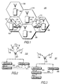
- FIG. 1 illustrates a communication system 100 in accordance with a preferred embodiment of the present invention.
- the communication system 100 includes a plurality of base sites 101-105 having respective service coverage areas 107-111 and a plurality of communication units 113 and 114.
- communication unit 113 is communicating with base site 101 via uplink communication signal 119 and base site 101 is communicating with communication unit 113 via downlink communication signal 116.
- communication unit 114 is communicating with base site 105 via uplink communication signal 121 and base site 105 is communicating with communication unit 114 via downlink communication signal 118.
- the communication system 100 may, for example, be an analog or digital cellular communication system, such as the Advanced Mobile Phone Service (AMPS) system, the Personal Digital Cellular (PDC) system, or the United States Digital Cellular (USDC) (GSM, USDC and AMPS systems are described in Electronic Industries Association/Telecommunications Association Industry Interim Standard 54 (IS-54).
- AMPS Advanced Mobile Phone Service
- PDC Personal Digital Cellular
- USDC United States Digital Cellular
- GSM Global System for Mobile Communications
- GSM Global System for Mobile Communications
- GSM Global System for Mobile Communications
- USDC United States Digital Cellular
- An exemplary communication unit e.g., 113
- an exemplary base site e.g., 101 are described in detail below with regard to FIGs. 2 and 3, respectively.
- Communication unit 113 while communicating with serving base site 101, monitors a downlink communication signal 118 transmitted by a distant base site 105.
- the distant base site 105 is assigned to receive uplink traffic channel frequencies that are either identical to, or adjacent to, the uplink traffic channel frequencies assigned for reception by the serving base site 101.
- the downlink communication signal 118 preferably is a control signal that includes the identity of the distant base site 105.
- the communication unit 113 determines a characteristic of signal usability for the downlink communication signal 118. In a preferred embodiment this characteristic is a received signal strength indication (RSSI) determined from monitoring the control channel of the distant base site 105.
- RSSI received signal strength indication
- the characteristic might be related to a bit error rate (BER), a frame erasure rate (PER), a carrier to interference ratio (C/I), or a carrier to noise ratio (C/N).
- the downlink characteristic of signal usability for the serving cell traffic channel frequency 116 comprising a received signal strength indication (RSSI), or a bit error rate (BER), a frame erasure rate (FER), a carrier to interference ratio (C/I), or a carrier to noise ratio (C/N) is also determined by the communication unit 113.
- the communication unit 113 transmits the characteristic of signal usability (e.g., RSSI) to the serving base site 101 via the uplink communication signal 119.
- the serving base site 101 receives the uplink communication signal 119 and compares the characteristic of signal usability to a usability threshold for the distant base site 105.
- the usability threshold is the RSSI level that corresponds to an undesired path loss between the communication unit 113 and the distant base site 105 or the desired path loss between the communication unit 113 and the serving base site 101.
- the serving base site 101 estimates a signal-to-noise ratio, as viewed by the distant base site 105, for the uplink communication signal 121 transmitted by the communication unit 114 being served by the distant base site 105.
- the signal-to-noise ratio is estimated by first determining a signal propagation loss (i.e., path loss) between the distant base site 105 and the communication unit 113 over the path 123 therebetween.
- the "noise" effectively is the level of cochannel or adjacent channel interference produced by the interfering communication unit 113.
- the serving base site 101 determines the signal propagation loss by subtracting the RSSI measurement (in decibel units) of the distant base site 105 contained in the uplink communication signal 119 received from the interfering communication unit 113 from the transmitted power (in decibel units) of the distant base site 105.
- the serving base site 101 determines the signal power of the uplink communication signal 119 (i.e., the "noise") incident upon the distant base site 105 by adding the signal propagation loss to the transmit power of the interfering communication unit 113.
- the serving base site 101 includes a database that contains the transmit powers of the other base sites 102-105 and the transmit powers of active communication units (e.g., 113) in its service coverage area 107 in accordance with conventional hand-off and uplink signal power control techniques.
- the base site database preferably includes uplink power control parameters (e.g., desired uplink RSSI) for the other base stations 102-105.
- the serving base site 101 knows the desired RSSI level at which the distant base site 105 intends to receive an uplink communication signal 121 from a communication unit 114 in the distant base site's service coverage area 111.
- the serving base site 101 After computing the noise (N) incident upon the distant base site 105 and retrieving the desired RSSI level (S) for an uplink communication signal 121 intended for reception by the distant base site 105, the serving base site 101 estimates the signal-to-noise ratio for the intended uplink communication signal 121 at the distant base site 105 by subtracting the signal power of the interfering uplink communication signal 119 from the desired RSSI level of the intended uplink communication signal 121.
- S/N ds (dB) desired RSSI ds - [P Tint - (P Tds - RSSI int )]
- S/N ds is the signal-to-noise ratio for a particular uplink communication signal 121 as perceived by the distant base site 105
- desired RSSI ds is the desired RSSI level at the distant base site 105 for the particular uplink communication signal 121
- P Tint is the transmit power of the interfering communication unit 113
- (P Tds - RSSI int ) is the signal propagation loss between the distant base site 105 and the interfering communication unit 113 (i.e., transmit power of the distant base site (P Tds ) less RSSI at the interfering communication unit 113 (RSSI int )).
- the parameter RSSI int is the same parameter measured by communication units in communication systems that employ
- the serving base site 101 Upon estimating the signal-to-noise ratio at the distant base site 105, the serving base site 101 compares the signal-to-noise ratio to a signal-to-noise threshold. When the signal-to-noise ratio is below the signal-to-noise threshold (e.g., 13 dB in the GSM system), the serving base site 101 transmits a channel designation signal (hand-off command) to the interfering communication unit 113 that directs the interfering communication unit 113 to hand-off to an uplink/downlink channel having a less aggressive reuse pattern, thereby reducing the interference produced by the interfering communication unit 113 as perceived by the distant base site 105.
- a channel designation signal hand-off command
- FIG. 2 illustrates a communication unit (e.g., 113) in accordance with a preferred embodiment of the present invention.
- the communication unit 113 comprises, an antenna 201, a receiver 203, a transmitter 205, and a processor 207.
- the receiver 203 preferably comprises well known front-end and backend circuitry, such as downconveners, mixers, filters, demodulators, and analog-to-digital converters that produce a baseband representation of the received downlink communication signal 116.
- the transmitter 205 preferably comprises mixers, amplifiers, attenuators, and modulation circuitry.
- the processor 207 preferably comprises a digital signal processor (DSP) or a microprocessor.
- DSP digital signal processor
- the communication unit 113 receives the downlink communication signals 116, 118 from the serving base site 101 and the distant base site 105, respectively, via the antenna 201.
- the downlink communication signal 118 received from the distant base site 105 is processed by the receiver 203 to determine a characteristic of signal usability for the downlink communication signal 118.
- the characteristic of signal usability is an RSSI.
- the RSSI is provided to the processor 207 where, in a preferred embodiment, the RSSI is configured within a transmit baseband signal 213.
- the transmit baseband signal 213 is provided to the transmitter 205 for transmission to the serving base site 101.
- the transmitter 205 transmits the RSSI to the serving base site 101 via the uplink communication signal 119.
- the communication unit 113 When the communication unit 113 receives a downlink communication signal 116 from the serving base site 101, the received signal is processed by the receiver 203 to extract the transmitted baseband information, including a hand-off command and uplink/downlink channels when sent.
- the receiver 203 provides the baseband information to the processor 207.
- the processor 207 interprets the hand-off command and generates a hand-off signal 211 that directs the transmitter 205 to hand-off to the assigned uplink/downlink channels.
- the transmitter 205 is handed off to an uplink/downlink channel that is on a less aggressive reuse pattern, thereby lessening the chance that the communication unit 113 will continue to be a potential interferer to the communication unit 114.
- the processor 207 when the communication unit 113 receives the downlink communication signal 118 from the distant base site 105, the processor 207 might additionally compare the received RSSI to a usability threshold to determine whether or not to include the RSSI within the transmit baseband signal 213 and to transmit the RSSI to the serving base site 101.
- the usability threshold is the same threshold as would be used at the serving base site 101 (e.g., 13 dB for a GSM system).
- the processor 207 determines that the received RSSI exceeds the usability threshold, the processor generates the transmit baseband signal 213, including the RSSI, and forwards the transmit baseband signal 213 to the transmitter 205 for transmission to the serving base site 101.
- the communication unit 113 performs a preliminary evaluation of the usability of the downlink signal 118 received from the distant base site 105.
- the serving base site 101 or some other means, must provide the usability threshold to the communication unit 113.
- the serving base site 101 might transmit a list of usability thresholds for various alternate base sites 102-105 to the communication unit 113 as part of the control information transmitted during the call set-up procedure.
- the communication unit 113 might receive a downlink communication signal 116 from the serving base site 101 that includes the pertinent information (e.g., transmit power of the distant base site 105, the desired uplink RSSI at the distant base site 105, and the signal-to-noise threshold) that the serving base site 101 uses in the preferred embodiment to estimate the signal-to-noise ratio for the uplink communication signal 121 at the distant base site 105.
- the processor 207 compares the received RSSI to the usability threshold.
- the communication unit 113 estimates the signal-to-noise ratio for the uplink communication signal 121 at the distant base site 105.
- the processor 207 compares the estimated signal-to-noise ratio with the signal-to-noise threshold.
- the communication unit 113 transmits a request to the serving base site 101 to be handed off to an uplink/downlink channel having a less aggressive reuse pattern, thereby reducing the interference produced by the interfering communication unit 113 as perceived by the distant base site 10.
- the communication unit 113 would require additional memory and processing capabilities to be able to perform the signal-to-noise computations for all the base sites with which it may be interfering.
- the communication unit 113 monitors a characteristic of the of the downlink communication signal 116 transmitted by the serving base site 101.
- this characteristic comprises a received signal strength indication (RSSI), however, one of ordinary skill in the art will recognize that other characteristics (bit error rate (BER), a frame erasure rate (PER), a carrier to interference ratio (C/I), or a carrier to noise ratio (C/N)) may be utilized as well.
- RSSI received signal strength indication
- BER received signal strength indication
- PER frame erasure rate
- C/I carrier to interference ratio
- C/N carrier to noise ratio
- the communication unit 113 transmits a request via the uplink communication signal 119, to the serving base site 101 to be handed off to an uplink/downlink channel having a less aggressive reuse pattern.
- the communication unit 113 transmits a request via the uplink communication signal 119, to the serving base site 101 to be handed off to an uplink/downlink channel having a less aggressive reuse pattern.
- FIG. 3 illustrates a base site (e.g., 101) in accordance with a preferred embodiment of the present invention.
- the base site 101 comprises, an antenna 301, a receiver 303, a transmitter 305, a processor 307, and a database 311.
- the receiver 303 preferably comprises well known front-end and backend circuitry, such as downconverters, mixers, filters, demodulators, and analog-to-digital converters that produce a baseband representation of the received uplink communication signal 119.
- the transmitter 305 preferably comprises mixers, amplifiers, attenuators, and modulation circuitry.
- the processor 307 preferably comprises a DSP or a microprocessor.
- the database 311 preferably comprises a random access memory (RAM) that contains uplink power control parameters, such as a desired RSSI level and a signal-to-noise threshold, for the distant base sites (102-105 in FIG. 1), the transmit power of the distant base sites 102-105, and the transmit powers of the communication units (e.g., 113) that are registered for service in the base site's service coverage area (107 in FIG. 1).
- RAM random access memory
- the base site 101 receives the uplink communication signal 119, including the characteristic of signal usability for a distant base site's downlink communication signal (118 in FIG. 1), from a communication unit 113 via the antenna 301.
- the uplink communication signal 119 is then processed by the receiver 303 to extract the characteristic of signal usability.
- the processor compares the characteristic of signal usability to a usability threshold. When the characteristic of signal usability exceeds the usability threshold, the processor 307 accesses the database 311 to obtain the parameters necessary to estimate the signal-to-noise ratio at the distant base site (e.g., 105 in FIG. 1).
- the processor 307 estimates the signal-to-noise ratio at the distant base site 105, as discussed above with regard to FIG.
- the hand-off command 309 instructs the communication unit 113 to hand-off to an uplink/downlink channel having a less aggressive reuse pattern, thereby reducing the interference produced by communication unit 113 as perceived by the distant base site 105.
- the hand-off command 309 when generated, is provided to the transmitter 305 for transmission to the communication unit 113.
- the transmitter 305 transmits the hand-off command 309 to the communication unit 113 via the downlink communication signal 116.
- the base site 101 upon receiving an uplink communication signal 119 that includes the characteristic of signal usability, proceeds directly with estimating the signal-to-noise ratio at the distant base site 105, comparing the signal-to-noise ratio to the signal-to-noise threshold for the distant base site 105 stored in the database 311, and generating, if necessary, the hand-off command 309 based on the comparison.
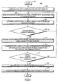
- FIG. 4 illustrates a logic flow diagram 400 of steps executed by a base site and a communication unit in accordance with the preferred embodiment of the present invention.
- the logic flow begins at 401.
- the communication unit is in communication with a first, or serving, base site of the communication system. That is, the communication unit is transmitting an uplink voice or data communication signal to the first base site via an uplink channel of the first communication resource and the first base site is transmitting a downlink voice, data, or control communication signal to the communication unit via a downlink channel of the first communication resource.
- the uplink and downlink channels of the first communication resource each comprises a time slot at a corresponding uplink or downlink frequency in accordance with known time division multiple access (TDMA) techniques.
- TDMA time division multiple access
- the communication unit While the communication unit is communicating with the first base site, the communication unit monitors (405) a downlink communication signal (e.g., a common control signal) transmitted by a second, or distant, base site.
- a downlink communication signal e.g., a common control signal
- the second base site is preferably configured to receive uplink communication signals at either the same frequency as, or a frequency substantially adjacent to, the frequency of the uplink communication signal transmitted by the communication unit.
- the communication unit determines (407) a characteristic of signal usability for the downlink communication signal. In the preferred embodiment, this determination comprises an RSSI.
- the communication unit transmits (409) the characteristic of signal usability to the first base site as part of an uplink communication signal.
- the first base site Upon receiving the characteristic of signal usability from the communication unit, the first base site first compares (410) the characteristic of signal usability to a usability threshold. When the characteristic of signal usability is less than or equal to the usability threshold, the first base site takes no action and the logic flow returns to step 405. However, when the characteristic of signal usability exceeds the usability threshold, the first base site determines (411) the signal propagation loss between the second base site and the communication unit based on the characteristic of signal usability (RSSI) and the transmit power of the second base site. In a preferred embodiment, this determination is simply a subtraction of the RSSI (in dB units) of the downlink communication signal from the transmit power (in dB units) of the second base site.
- RSSI characteristic of signal usability
- the first base site Upon determining the signal propagation, or path, loss between the communication unit and the second base site, the first base site uses the signal propagation loss to estimate (413) a signal-to-noise ratio at the second base site.
- the signal-to-noise ratio computation is described in detail above with regard to FIG. 1.
- the first base site then compares (415) the estimated signal-to-noise ratio to a signal-to-noise threshold for the second base site.
- the signal-to-noise threshold preferably comprises the minimum acceptable signal-to-noise ratio to maintain a particular signal quality. For example, in the GSM cellular system, the signal-to-noise threshold is approximately 13 dB.
- the first base site when the signal-to-noise ratio is greater than or equal to the signal-to-noise threshold, the first base site takes no action and the logic flow returns to step 405. However, when the signal-to-noise ratio is less than the signal-to-noise threshold, the first base site generates a hand-off command instructing the communication unit to hand-off to an uplink/downlink channel having a less aggressive reuse pattern. The first base site then transmits (419) the hand-off command to the communication unit via a downlink communication signal. Upon receiving the hand-off command, the communication unit performs a hand-off (421) to the assigned uplink/downlink channel having a less aggressive reuse pattern, and the logic flow ends (417).
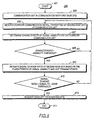
- FIG. 5 illustrates a logic flow diagram 500 of steps executed by a base site and a communication unit in accordance with the first alternative embodiment of the present invention.
- the logic flow begins (501) when the communication unit is in communication (503) with the first base site of the communication system. Similar to the logic flow of FIG. 4, the communication unit monitors (505) a downlink communication signal transmitted by a second base site and determines (507) a characteristic of signal usability for the downlink communication signal. However, in this embodiment, the communication unit compares (509) the characteristic of signal usability to a usability threshold. When the characteristic of signal usability is less than or equal to the usability threshold, the communication unit takes no further action other than simply returning to step 505.
- the communication unit transmits (513) an uplink communication signal containing the characteristic of signal usability to the first base site.
- the first base site estimates (515) the signal-to-noise ratio at the second base site based on the characteristic of signal usability and the transmit power of the communication unit, compares (517) the signal-to-noise ratio to a signal-to-noise threshold. If the signal-to-noise ratio is greater than or equal to the signal-to-noise threshold, the logic flow returns to step 505.
- the serving base station transmits (519) a hand-off command to the communication unit instructing the communication unit to hand-off to a particular uplink/downlink channel on a less aggressive reuse pattern.
- the communication Upon receiving the hand-off command, the communication performs a hand-off (521) and the logic flow ends (511).
- FIG. 6 illustrates a logic flow diagram 600 of steps executed by a communication unit in accordance with the second alternative embodiment.
- the logic flow begins (601) when. the communication unit is in communication (603) with a first base site of the communication system. Similar to the logic flows of FIGs. 4 and 5, the communication unit monitors (605) a downlink communication signal transmitted by a second base site and determines (607) a characteristic of signal usability for the downlink communication signal. However, in this embodiment, the communication unit performs all the functions of determining when the characteristic of signal usability exceeds the usability threshold, and then requests a hand-off from the serving base site.
- the communication unit compares (609) the characteristic of signal usability to a usability threshold.
- the logic flow returns to step 605.
- the communication unit estimates (612) the signal-to-noise ratio at the second base site based on the characteristic of signal usability and the communication unit's transmit power, and compares (613) the signal-to-noise ratio to a signal-to-noise threshold.
- the communication unit might request the necessary quantities (e.g., desired RSSI level, transmit power of the second base site, and signal-to-noise threshold) from the first base site's database to perform the signal-to-noise computation and comparison.
- the communication unit might maintain its own database and receive database updates from the first base site.
- the logic flow returns to step 605.
- the communication unit requests from the serving station, a hand-off to an uplink/downlink channel having a less aggressive reuse pattem (615), and the logic flow ends (611).
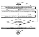
- FIG. 7 illustrates a logic flow diagram 700 of steps executed by a communication unit in the third alternative embodiment of the present invention.
- the logic flow begins at 701, where the communication unit is in communication (703) with the serving base site.
- the communication unit monitors (705) a the downlink communication to determine a characteristic (707) of the of the downlink communication signal transmitted by the serving base site.
- this characteristic comprises a received signal strength indication (RSSI).
- RSSI received signal strength indication
- the characteristic might be related to a bit error rate (BER), a frame erasure rate (PER), a carrier to interference ratio (C/I), or a carrier to noise ratio (C/N).
- the communication unit compares the RSSI to a threshold (709).
- the logic flow returns to step 705. However, if the RSSI of the downlink communication signal is below the threshold, the communication unit transmits a request (711) to the serving base site to be handed off to an uplink/downlink channel having a less aggressive reuse pattern, thereby reducing the interference produced by the interfering communication unit as perceived by the distant base site.
- the logic flow ends at 713.
- FIG. 8 illustrates a cellular coverage area using simultaneous multi-level reuse patterns in accordance with a preferred embodiment of the present invention.
- the cellular coverage area includes a plurality of base sites 101 and 105 having respective service coverage areas 107 and 111 and a plurality of communication units 113 and 114.
- communication unit 113 is communicating with base site 101 via uplink communication signal 119 and base site 101 is communicating with communication unit 113 via downlink communication signal 116.
- communication unit 114 is communicating with base site 105 via uplink communication signal 121 and base site 105 is communicating with communication unit 114 via downlink communication signal 118.
- the base sites shown in FIG. 8 are not sectorized, but one of ordinary skill in the art will recognize that one site commonly has up to six 60 degree sectors.
- each site operates on both a four site reuse pattern and a seven site reuse pattern, whereby one set of channels (1-4) is dedicated to the four site reuse pattern while another set of channels (A-F) is dedicated to the seven site reuse pattern.
- one set of channels (1-4) is dedicated to the four site reuse pattern while another set of channels (A-F) is dedicated to the seven site reuse pattern.
- base site 101 is capable of communicating on those channels associated with groups D and 1
- base site 105 is capable of communicating on those channels associated with groups F and 1.
- communication unit 113 is communicating with base site 101 on a particular uplink/downlink channel belonging to group 1, while communication unit 114 is communicating with base site 105 on the same (or adjacent) uplink/downlink channel as that of communication unit 113.
- the transmit power of the communication unit 113 as well as the transmit power of the base site 101 must be increased to account for an increase in path losses between the serving base site 101 and the communication unit 113.
- This increased transmit power has the potential to interfere with the same (or adjacent) uplink/downlink frequency being used by communication unit 114. That is, the higher power transmission of communication unit 113 and base site 101 can increase the cochannel or adjacent channel interference in coverage area 111 as viewed by communication unit 114.
- base site 101 transmits a hand-off command to communication unit 113 that directs communication unit 113 to hand-off to an uplink/downlink channel associated with group D. Since base site 105 does not operate with channels belonging to group D, the interference produced by communication unit 113 as perceived by the distant base site 105 (and similarly, all sites utilizing group 1 channels) has been reduced.
Claims (6)
- Verfahren zur Aufrechterhaltung der Verbindungsqualität in einem Kommunikationssystem (100), umfassend die Schritte:Kommunizieren zwischen einer ersten Basisanlage (101) und einer Kommunikationseinheit (113) auf einem ersten Kanal, wobei der erste Kanal einer ersten Gruppe von Kanälen zugeordnet ist, wobei dem ersten Kanal eine erste Identifikationsnummer zugeordnet ist; undÜberwachen, durch die Kommunikationseinheit (113), eines zweiten von einer zweiten Basisanlage (105) gesendeten Kanals, wobei der zweite Kanal der ersten Gruppe von Kanälen zugeordnet ist, gekennzeichnet durch:Abschätzen des Signal-zu-Rausch-Verhältnisses, wie von der zweiten Basisanlage aus gesehen, für ein von einer zweiten Kommunikationseinheit (114) gesendetes Aufwärts-Kommunikationssignal (121) durch Subtrahieren einer Signalleistung des ersten Kanals (119) von einem erwünschten RSSI-Niveau des von der zweiten Kommunikationseinheit gesendeten Aufwärts-Kommunikationssignals; undÜbergeben der Kommunikationseinheit an einen dritten Kanal, basierend auf dem abgeschätzten Signal-zu-Rausch-Verhältnis, wobei der dritte Kanal einer zweiten Gruppe von Kanälen zugeordnet ist, welche ein weniger aggressives Wiederverwendungsmuster aufweist als die erste Gruppe von Kanälen.
- Verfahren nach Anspruch 1, wobei die erste Identifikationsnummer einer bestimmten Frequenz eines Kommunikationssystems (100) entspricht.
- Verfahren nach Anspruch 1, wobei die erste Identifikationsnummer einer bestimmten Frequenz und einem Zeit-Slot eines Kommunikationssystems (100) entspricht.
- Verfahren nach Anspruch 1, wobei der Schritt des Bestimmens einer Charakteristik des zweiten Kanals den Schritt des Bestimmens eines Empfangssignal-Stärkeindikators des zweiten Kanals umfasst.
- Verfahren nach Anspruch 1, wobei der Schritt des Bestimmens der Charakteristik des zweiten Kanals den Schritt des Bestimmens einer Bitfehlerrate des zweiten Kanals umfasst.
- Mobilfunkeinheit, die in der Lage ist, Interferenzen abzumildern, umfassend:einen Sender (205) zum Senden an eine erste Basisanlage auf einem ersten Kanal, wobei der erste Kanal einer ersten Gruppe von Kanälen zugeordnet ist; undeinen mit dem Sender verbundenen Empfänger (203) zum Überwachen eines zweiten von einer zweiten Basisanlage aus gesendeten Kanals, wobei der zweite Kanal der ersten Gruppe von Kanälen zugeordnet ist, gekennzeichnet durch:einen Prozessor (207) zum Abschätzen des Signal-zu-Rausch-Verhältnisses, wie von der zweiten Basisanlage aus gesehen, für ein von einer zweiten Kommunikationseinheit (114) gesendetes Aufwärts-Kommunikationssignal (121) durch Subtrahieren einer Signalleistung des ersten Kanals (119) von einem erwünschten RSSI-Niveau des von der zweiten Kommunikationseinheit gesendeten Aufwärts-Kommunikationssignals; undMittel zur Übergabe der Mobileinheit an einen dritten Kanal, basierend auf dem abgeschätzten Signal-zu-Rausch-Verhältnis, wobei der dritte Kanal einer zweiten Gruppe von Kanälen zugeordnet ist, welche ein weniger aggressives Wiederverwendungsmuster aufweist als die erste Gruppe von Kanälen.
Applications Claiming Priority (3)
| Application Number | Priority Date | Filing Date | Title |
|---|---|---|---|
| US59404896A | 1996-01-30 | 1996-01-30 | |
| US594048 | 1996-01-30 | ||
| PCT/US1996/019420 WO1997028619A1 (en) | 1996-01-30 | 1996-11-12 | Method and apparatus for maintaining call quality in a communication system |
Publications (3)
| Publication Number | Publication Date |
|---|---|
| EP0818090A1 EP0818090A1 (de) | 1998-01-14 |
| EP0818090A4 EP0818090A4 (de) | 1999-06-30 |
| EP0818090B1 true EP0818090B1 (de) | 2004-10-20 |
Family
ID=24377291
Family Applications (1)
| Application Number | Title | Priority Date | Filing Date |
|---|---|---|---|
| EP96944761A Expired - Lifetime EP0818090B1 (de) | 1996-01-30 | 1996-11-12 | Verfahren und vorrichtung zum sicherstellen der anrufqualität in einem kommunikationssystem |
Country Status (7)
| Country | Link |
|---|---|
| US (1) | US5822699A (de) |
| EP (1) | EP0818090B1 (de) |
| AU (1) | AU689055B2 (de) |
| CA (1) | CA2215725C (de) |
| DE (1) | DE69633663T2 (de) |
| IL (1) | IL121370A0 (de) |
| WO (1) | WO1997028619A1 (de) |
Families Citing this family (24)
| Publication number | Priority date | Publication date | Assignee | Title |
|---|---|---|---|---|
| US6011970A (en) * | 1997-07-23 | 2000-01-04 | Nortel Networks Corporation | Method and system for assuring near uniform capacity and quality of channels in cells of wireless communications systems having cellular architectures |
| JP3856253B2 (ja) * | 1997-10-16 | 2006-12-13 | ソニー株式会社 | セルラー無線通信システム及び基地局 |
| JP3109504B2 (ja) * | 1998-03-27 | 2000-11-20 | 日本電気株式会社 | セルラシステムおよびセルラシステムの隣接周波数干渉回避方法と移動局 |
| GB9817292D0 (en) | 1998-08-07 | 1998-10-07 | Nokia Mobile Phones Ltd | Digital video coding |
| US6785249B2 (en) * | 1998-10-05 | 2004-08-31 | Qualcomm, Incorporated | Method and apparatus for detecting forward and reverse link imbalance in digital cellular communication systems |
| GB2343330A (en) * | 1998-10-29 | 2000-05-03 | Fujitsu Ltd | Soft handoff method using a backup link |
| US6349208B1 (en) * | 1999-04-28 | 2002-02-19 | Nokia Corporation | Apparatus and associated method for selectively permitting initiation or cell reselection in a radio communication system |
| GB9921007D0 (en) * | 1999-09-06 | 1999-11-10 | Nokia Telecommunications Oy | Quality measurement |
| US6553016B1 (en) * | 1999-12-20 | 2003-04-22 | Telfonaktiebolaget Lm Ericsson (Publ) | Downlink power control at soft handover |
| US7103382B2 (en) * | 2001-07-10 | 2006-09-05 | Kyocera Wireless Corp. | System and method for receiving and transmitting information in a multipath environment |
| US7853260B2 (en) * | 2002-04-29 | 2010-12-14 | Nokia Corporation | Method and apparatus for cell identification for uplink interference avoidance using inter-frequency measurements |
| US20030224730A1 (en) * | 2002-04-29 | 2003-12-04 | Peter Muszynski | Method and apparatus for selection of downlink carriers in a cellular system using multiple downlink carriers |
| US20030224733A1 (en) * | 2002-04-29 | 2003-12-04 | Uwe Schwarz | Method and apparatus for estimating signal quality for uplink interference avoidance |
| US7424296B2 (en) * | 2002-04-29 | 2008-09-09 | Nokia Corporation | Method and apparatus for soft handover area detection for uplink interference avoidance |
| US6681112B1 (en) * | 2002-04-29 | 2004-01-20 | Nokia Corporation | Handovers of user equipment connections in wireless communications systems |
| US7525948B2 (en) * | 2002-04-29 | 2009-04-28 | Nokia Corporation | Method and apparatus for utilizing synchronization information |
| US20040047312A1 (en) * | 2002-04-29 | 2004-03-11 | Peter Muszynski | Method and apparatus for UL interference avoidance by DL measurements and IFHO |
| US20040022217A1 (en) * | 2002-04-29 | 2004-02-05 | Sari Korpela | Method and apparatus for soft handover area detection using inter-band measurements |
| US7046655B2 (en) * | 2002-08-15 | 2006-05-16 | Interdigital Technology Corporation | Wireless communication method and system for minimizing interference by determining mobile station zone locations and potential conflicts between cell zones |
| US7853292B2 (en) * | 2004-05-06 | 2010-12-14 | Alcatel-Lucent Usa Inc. | Distributed resource management for enhanced dedicated channel |
| US8705506B2 (en) * | 2007-11-16 | 2014-04-22 | Qualcomm Incorporated | Time reservation for a dominant interference scenario in a wireless communication network |
| US8515372B2 (en) * | 2008-03-24 | 2013-08-20 | Freescale Semiconductor, Inc. | Receiver configurable in a plurality of modes |
| US8249606B1 (en) * | 2008-07-30 | 2012-08-21 | Optimi Corporation | Frequency planning optimization for mobile communications |
| US9554390B2 (en) * | 2015-05-18 | 2017-01-24 | The Aerospace Corporation | Interference control in shared bands |
Family Cites Families (8)
| Publication number | Priority date | Publication date | Assignee | Title |
|---|---|---|---|---|
| JP2558684B2 (ja) * | 1987-03-31 | 1996-11-27 | 日本電信電話株式会社 | 移動無線チヤネル制御方式 |
| US5148548A (en) * | 1989-12-19 | 1992-09-15 | Northern Telecom Limited | Method of monitoring cellular radio channels to avoid adjacent and co-channel interference |
| US5038399A (en) * | 1990-05-21 | 1991-08-06 | Motorola, Inc. | Method for assigning channel reuse levels in a multi-level cellular system |
| CA2023053C (en) * | 1990-08-10 | 1994-06-28 | Frank D. Benner | Method for assigning telecommunications channels in a cellular telephone system |
| US5319796A (en) * | 1990-12-14 | 1994-06-07 | Motorola, Inc. | Communication system that avoids co-channel interference |
| EP0530165A3 (en) * | 1991-08-23 | 1993-08-11 | Telefonaktiebolaget L M Ericsson | Mobile station-controlled handoff |
| US5287544A (en) * | 1991-10-17 | 1994-02-15 | Motorola, Inc. | Method of channel assignment by matching channel interference with channel link loss |
| US5594946A (en) * | 1995-02-28 | 1997-01-14 | Motorola, Inc. | Method and apparatus for mitigating interference produced by a communication unit in a communication system |
-
1996
- 1996-11-12 DE DE69633663T patent/DE69633663T2/de not_active Expired - Lifetime
- 1996-11-12 IL IL12137096A patent/IL121370A0/xx unknown
- 1996-11-12 CA CA002215725A patent/CA2215725C/en not_active Expired - Fee Related
- 1996-11-12 EP EP96944761A patent/EP0818090B1/de not_active Expired - Lifetime
- 1996-11-12 WO PCT/US1996/019420 patent/WO1997028619A1/en active IP Right Grant
- 1996-12-12 AU AU13300/97A patent/AU689055B2/en not_active Ceased
-
1997
- 1997-09-05 US US08/926,248 patent/US5822699A/en not_active Expired - Lifetime
Also Published As
| Publication number | Publication date |
|---|---|
| EP0818090A4 (de) | 1999-06-30 |
| US5822699A (en) | 1998-10-13 |
| DE69633663T2 (de) | 2005-03-24 |
| EP0818090A1 (de) | 1998-01-14 |
| CA2215725A1 (en) | 1997-08-07 |
| AU1330097A (en) | 1997-08-22 |
| IL121370A0 (en) | 1999-10-28 |
| DE69633663D1 (de) | 2004-11-25 |
| CA2215725C (en) | 2001-06-12 |
| AU689055B2 (en) | 1998-03-19 |
| WO1997028619A1 (en) | 1997-08-07 |
Similar Documents
| Publication | Publication Date | Title |
|---|---|---|
| EP0818090B1 (de) | Verfahren und vorrichtung zum sicherstellen der anrufqualität in einem kommunikationssystem | |
| EP0758505B1 (de) | Verfahren und gerät zur verminderung der in einer telekommunikationsandordnung durch eine kommunikationseinheit verursachten interferenzen | |
| US6463294B1 (en) | Reducing interference in a mobile communications system | |
| JP3966369B2 (ja) | Cdma無線加入者網システムの順方向トラヒックチャンネル電力制御方法及びその装置 | |
| US6546252B1 (en) | System and method for estimating interfrequency measurements used for radio network function | |
| EP1437913B1 (de) | Aufbau von Makrodiversity mit Zufallszugriffsverbindungen in einem zellularen Funkkommunikationssystem | |
| US7702336B2 (en) | Channel assignment based on spatial strategies in a wireless network using adaptive antenna arrays | |
| EP0991206B1 (de) | CDMA-Leistungsregelung für Funkruf- und Verkehrskanals-Anfangsleistung | |
| EP0569559B1 (de) | Verfahren zu verbesserter auswahl eines gsm interferenzbandes und zur umlegung mit reduzierter ausgangsleistung | |
| EP1710932B1 (de) | Störungsvermeidung in Funkkommunikationssystemen | |
| KR100493685B1 (ko) | 통신채널 선택용 기지국 장치 | |
| CA2316206A1 (en) | Variable handoff hysteresis in a radio communication system | |
| EP0872140B1 (de) | Handover-auswahlverfahren für und zellulares funksystem | |
| US7978673B1 (en) | Channel allocation based on random plus planned processes | |
| US5765103A (en) | Spatially-oriented subscriber configuration in a fixed wireless system | |
| GB2318252A (en) | Channel Allocation in a Cellular Radio Network | |
| KR100708502B1 (ko) | 무선 네트워크 기능으로 사용된 중간 주파수 측정값을추정하는 시스템 및 방법 |
Legal Events
| Date | Code | Title | Description |
|---|---|---|---|
| PUAI | Public reference made under article 153(3) epc to a published international application that has entered the european phase |
Free format text: ORIGINAL CODE: 0009012 |
|
| AK | Designated contracting states |
Kind code of ref document: A1 Designated state(s): DE FI FR GB SE |
|
| 17P | Request for examination filed |
Effective date: 19980209 |
|
| A4 | Supplementary search report drawn up and despatched |
Effective date: 19990517 |
|
| AK | Designated contracting states |
Kind code of ref document: A4 Designated state(s): DE FI FR GB SE |
|
| 17Q | First examination report despatched |
Effective date: 20030819 |
|
| GRAP | Despatch of communication of intention to grant a patent |
Free format text: ORIGINAL CODE: EPIDOSNIGR1 |
|
| GRAS | Grant fee paid |
Free format text: ORIGINAL CODE: EPIDOSNIGR3 |
|
| GRAA | (expected) grant |
Free format text: ORIGINAL CODE: 0009210 |
|
| AK | Designated contracting states |
Kind code of ref document: B1 Designated state(s): DE FI FR GB SE |
|
| PG25 | Lapsed in a contracting state [announced via postgrant information from national office to epo] |
Ref country code: SE Free format text: LAPSE BECAUSE OF FAILURE TO SUBMIT A TRANSLATION OF THE DESCRIPTION OR TO PAY THE FEE WITHIN THE PRESCRIBED TIME-LIMIT Effective date: 20041020 Ref country code: FI Free format text: LAPSE BECAUSE OF FAILURE TO SUBMIT A TRANSLATION OF THE DESCRIPTION OR TO PAY THE FEE WITHIN THE PRESCRIBED TIME-LIMIT Effective date: 20041020 |
|
| REG | Reference to a national code |
Ref country code: GB Ref legal event code: FG4D |
|
| REF | Corresponds to: |
Ref document number: 69633663 Country of ref document: DE Date of ref document: 20041125 Kind code of ref document: P |
|
| PLBE | No opposition filed within time limit |
Free format text: ORIGINAL CODE: 0009261 |
|
| STAA | Information on the status of an ep patent application or granted ep patent |
Free format text: STATUS: NO OPPOSITION FILED WITHIN TIME LIMIT |
|
| ET | Fr: translation filed | ||
| 26N | No opposition filed |
Effective date: 20050721 |
|
| REG | Reference to a national code |
Ref country code: GB Ref legal event code: 732E Free format text: REGISTERED BETWEEN 20110127 AND 20110202 |
|
| REG | Reference to a national code |
Ref country code: DE Ref legal event code: R081 Ref document number: 69633663 Country of ref document: DE Owner name: MOTOROLA MOBILITY, INC. ( N.D. GES. D. STAATES, US Free format text: FORMER OWNER: MOTOROLA, INC., SCHAUMBURG, ILL., US Effective date: 20110324 |
|
| REG | Reference to a national code |
Ref country code: FR Ref legal event code: TP Owner name: MOTOROLA MOBILITY, INC., US Effective date: 20110912 |
|
| PGFP | Annual fee paid to national office [announced via postgrant information from national office to epo] |
Ref country code: FR Payment date: 20141118 Year of fee payment: 19 Ref country code: GB Payment date: 20141127 Year of fee payment: 19 Ref country code: DE Payment date: 20141128 Year of fee payment: 19 |
|
| REG | Reference to a national code |
Ref country code: DE Ref legal event code: R119 Ref document number: 69633663 Country of ref document: DE |
|
| GBPC | Gb: european patent ceased through non-payment of renewal fee |
Effective date: 20151112 |
|
| REG | Reference to a national code |
Ref country code: FR Ref legal event code: ST Effective date: 20160729 |
|
| PG25 | Lapsed in a contracting state [announced via postgrant information from national office to epo] |
Ref country code: GB Free format text: LAPSE BECAUSE OF NON-PAYMENT OF DUE FEES Effective date: 20151112 Ref country code: DE Free format text: LAPSE BECAUSE OF NON-PAYMENT OF DUE FEES Effective date: 20160601 |
|
| PG25 | Lapsed in a contracting state [announced via postgrant information from national office to epo] |
Ref country code: FR Free format text: LAPSE BECAUSE OF NON-PAYMENT OF DUE FEES Effective date: 20151130 |
|
| P01 | Opt-out of the competence of the unified patent court (upc) registered |
Effective date: 20230520 |