EP0817497A2 - Loop filtering method for reducing blocking effects and ringing noise of a motion-compensated image - Google Patents
Loop filtering method for reducing blocking effects and ringing noise of a motion-compensated image Download PDFInfo
- Publication number
- EP0817497A2 EP0817497A2 EP19960306903 EP96306903A EP0817497A2 EP 0817497 A2 EP0817497 A2 EP 0817497A2 EP 19960306903 EP19960306903 EP 19960306903 EP 96306903 A EP96306903 A EP 96306903A EP 0817497 A2 EP0817497 A2 EP 0817497A2
- Authority
- EP
- European Patent Office
- Prior art keywords
- map information
- filtering method
- edge map
- weight factors
- edge
- Prior art date
- Legal status (The legal status is an assumption and is not a legal conclusion. Google has not performed a legal analysis and makes no representation as to the accuracy of the status listed.)
- Ceased
Links
Images


Classifications
-
- H—ELECTRICITY
- H04—ELECTRIC COMMUNICATION TECHNIQUE
- H04N—PICTORIAL COMMUNICATION, e.g. TELEVISION
- H04N19/00—Methods or arrangements for coding, decoding, compressing or decompressing digital video signals
- H04N19/85—Methods or arrangements for coding, decoding, compressing or decompressing digital video signals using pre-processing or post-processing specially adapted for video compression
- H04N19/89—Methods or arrangements for coding, decoding, compressing or decompressing digital video signals using pre-processing or post-processing specially adapted for video compression involving methods or arrangements for detection of transmission errors at the decoder
-
- H—ELECTRICITY
- H04—ELECTRIC COMMUNICATION TECHNIQUE
- H04N—PICTORIAL COMMUNICATION, e.g. TELEVISION
- H04N19/00—Methods or arrangements for coding, decoding, compressing or decompressing digital video signals
- H04N19/85—Methods or arrangements for coding, decoding, compressing or decompressing digital video signals using pre-processing or post-processing specially adapted for video compression
- H04N19/86—Methods or arrangements for coding, decoding, compressing or decompressing digital video signals using pre-processing or post-processing specially adapted for video compression involving reduction of coding artifacts, e.g. of blockiness
-
- H—ELECTRICITY
- H04—ELECTRIC COMMUNICATION TECHNIQUE
- H04N—PICTORIAL COMMUNICATION, e.g. TELEVISION
- H04N19/00—Methods or arrangements for coding, decoding, compressing or decompressing digital video signals
- H04N19/60—Methods or arrangements for coding, decoding, compressing or decompressing digital video signals using transform coding
- H04N19/61—Methods or arrangements for coding, decoding, compressing or decompressing digital video signals using transform coding in combination with predictive coding
-
- H—ELECTRICITY
- H04—ELECTRIC COMMUNICATION TECHNIQUE
- H04N—PICTORIAL COMMUNICATION, e.g. TELEVISION
- H04N19/00—Methods or arrangements for coding, decoding, compressing or decompressing digital video signals
- H04N19/80—Details of filtering operations specially adapted for video compression, e.g. for pixel interpolation
- H04N19/82—Details of filtering operations specially adapted for video compression, e.g. for pixel interpolation involving filtering within a prediction loop
Definitions
- the present invention relates to a loop filtering method capable of reducing blocking effects and ringing noise, and more particularly, to a loop filtering method capable of reducing blocking effects and ringing noise of a motion-compensated image.
- This block-based processing induces the well-known blocking effects and ringing noise, in particular, when an image is highly compressed.
- the blocking effects induce a viewer who views a decompressed image displayed on a screen, to feel the boundary between the blocks in the visual sense.
- Typical blocking effects are grid noise in the monotone area and staircase noise along the image edges.
- the ringing noise induces sinusoidal traces on the practical edges of an image.
- a signal adaptive loop filtering method of largely reducing blocking effects and ringing noise comprising the steps of:
- FIG. 1 is a block diagram showing an encoding apparatus employing a loop filter according to a preferred embodiment of the present invention, which shows an encoding apparatus related to H.263.
- FIG. 1 apparatus since blocks excepting a loop filter 310 proposed by the present invention are well-known to those who are concerned with high efficiency encoding systems including a prediction encoder, the operation with regard to such blocks will be described briefly.
- an input video signal is input to a subtracter 301, a first switch 302 and a prediction encoder 309.
- the subtracter 301 subtracts a filtered signal by the loop filter 310 from the input video signal, an output signal of which is applied to the first switch 302.
- the first switch 302 selects either the input video signal or the output signal of the subtracter 301 according to the control of an encoding controller 305, and the selected signal is applied to an orthogonal transformer 303.
- the encoding controller 305 controls the first switch 302 so that the input video signal is applied to the orthogonal transformer 303 in the case of an intra coding mode, and the output signal of the subtracter 301 is applied to the orthogonal transformer 303 in the case of an inter coding mode.
- a signal passing through the orthogonal transformer 303 and a quantizer 304 is applied to a video multiplexer encoder (not shown) and a dequantizer 306.
- the dequantizer 306 dequantizes the applied signal, and the dequantized signal is supplied to an inverse-orthogonal transformer 307.
- An adder 308 adds an output signal of a second switch 311 and that of the inverse-orthogonal transformer 307, and the added signal is supplied to the prediction encoder 309.
- the prediction encoder 309 performs a motion estimation and compensation using the input video signal and a video signal stored in an internal memory, and the resultant signal by the motion estimation and compensation is stored in the internal memory.
- the prediction encoder 309 also outputs motion vector V obtained by the motion estimation to the video multiplexer encoder.
- the loop filter 310 in accordance to the present invention described below performs the filtering with regard to the picture stored in the prediction encoder 309. An output signal of the loop filter 310 is supplied to the subtracter 301 and the second switch 311.
- the second switch 311 which is controlled by the encoding controller 305, cuts off what the input signal has supplied to the adder 308 in the case of the intra coding mode, and makes the input signal supplied to the adder 308 in the case of the inter coding mode.
- the encoding controller 305 controls the above operation of Figure 1 apparatus, generates a flag P representing intra/inter modes, a quantizer indicator signal qz and a flag t representing whether or not a signal is transmitted.
- FIG. 2 is a block diagram showing the loop filter 310 of Figure 1 apparatus.
- the loop filter 310 of Figure 2 includes an image store 10, a binary edge mapping unit 100 and a signal adaptive filter portion 200.
- the image store 10 stores data supplied from the prediction encoder 309 in which the motion estimation and compensation encoding are performed.
- the binary edge mapping unit 100 includes a gradient image generator 20, a global edge mapper 30, a local edge mapper 40 and a logical OR unit 50, which generates binary edge map information on which global edges and local edges of a motion-compensated image are reflected.
- the signal adaptive filter portion 200 includes a filter determiner 60, an average filter 70 and a weighted filter 80, which filters the motion-compensated image data using one of the average filter and the weighted filter to be described below based on the binary edge map information.
- the grid noise and the ringing noise are mitigated in the signal adaptive filter portion 200.
- the gradient image generator 20 generates gradient image data using the image data stored in the image store 10.
- the gradient image generator 20 applies a vertical Sobel gradient operator and a horizontal Sobel gradient operator to the motion-compensated image, that is, the image data stored in the image store 10, so as to generate a gradient image.
- the gradient image data obtained by the gradient image generator 20 is supplied to the global edge mapper 30 and the local edge mapper 40.
- the global edge mapper 30 produces a global edge map with respect to the whole image
- the local edge mapper 40 divides the whole image into blocks having a predetermined magnitude and produces a local edge map with respect to each of blocks.
- the global edge mapper 20 calculates an edge value (i, j) corresponding to each pixel using the following equation (1). If
- ⁇ h and ⁇ v represent a horizontal gradient image and a vertical gradient image at a location (i, j) obtained by the horizontal Sobel gradient operator and the vertical Sobel gradient operator, respectively.
- represents a gradient value at a location (i, j) and T g is a global threshold value which is "100" when each pixel within an image has 256 gray levels.
- the global edge mapper 30 determines an edge value corresponding to the pixel as "1". On the other hand, if a gradient value corresponding to a pixel is smaller than the global threshold value T g , the global edge mapper 30 determines an edge value (i, j) corresponding to the pixel as "0".
- the global edge map information obtained by applying the above equation to the whole image is supplied to the logical OR unit 50.
- the local edge mapper 40 produces a local edge map using the output of the gradient image generator 20.
- the local edge mapper 40 calculates a local threshold value with respect to each of all M 1 x M 2 blocks of the gradient image, and calculates local edge values with respect to all gradient values contained in corresponding block using the calculated local threshold value.
- the block-based processing techniques such as DCT transform and quantization, process signals with respect to an 8x8 block containing basically 8x8 pixels.
- the local edge mapper 40 according to the one embodiment of the present invention is also designed to draw a local edge map by using an 8x8 block.
- the present invention is not limited to the block of such a size.
- the local threshold value T n with respect to a n-th 8x8 block in the gradient image is defined by the following equations (2) - (4).
- T n
- g (i,j) represents a gradient value
- R n represents a n-th 8x8 block region m n
- ⁇ n represent a mean value and a standard deviation of a n-th 8x8 block of the gradient image, respectively.
- T g represents a global threshold value and N is 64 in the case of an 8x8 block. If the n-th 8x8 block is homogenous, a ratio ⁇ n /m n tends to be "0" with the result that T n becomes very close to T g . Meanwhile, if the n-th 8x8 block is part of a complicated image, the ratio ⁇ n /m n increases. As a result, T n becomes smaller than T g . This small T n is used in drawing a detail edge map which is not classified as a global edge by T g .
- the local edge mapper 40 individually compares the local threshold value T n with respect to the n-th 8x8 block with a part of the gradient values within the block, in magnitude.
- the part of the gradient values corresponds to 6x6 pixels within the 8x8 block excluding the boundary pixels within the 8x8 block. If the gradient value used for drawing the local edge map is defined as described above, the detailed information is protected from blurring, and the grid noise is prevented from being detected as an image edge. If each gradient value being allowable within the n-th 8x8 block region R n is larger than or equal to the local threshold value T n , the local edge mapper 40 determines a local edge value corresponding to the gradient value as "1".
- the local edge mapper 40 determines a local edge value corresponding to the gradient value as "0".
- the local edge mapper 40 generates local edge map information by performing the operation procedure including an 8x8 block division, local edge value calculation and calculation of a local edge value using allowable gradient values of each block, with respect to all gradient values generated by the gradient image generator 20.
- the generated local edge map information is supplied to the logical OR unit 50.
- the logical OR unit 50 performs a logical OR operation of the global edge map information and the local edge map information which are related to each other with respect to a pixel location.
- the logical OR unit 50 performs a logical OR operation with respect to all global edge values on the global edge map and all local edge values on the local edge map, and outputs binary edge map information representing the result to the filter determiner 60.
- the binary edge map produced by the logical OR unit 50 is conceptually shown in Figure 3. On the binary edge map of Figure 3, the shaded squares are represented the edge points each of which has the edge value "1".
- the filter determiner 60 stores the binary edge map information supplied from the logical OR unit 50.
- the motion compensated image is classified into two areas such as an edge area and a homogeneous area by a binary edge map.
- the present invention uses the filter determiner 60.
- the average filter 70 and the weighted filter 80 described later use a 3x3 filter window.
- a filter window used in the filter determiner 60 has a 3x3 size, too.
- the filter determiner 60 judges whether a region on the binary edge map where the filter window is located is an edge area or a homogeneous area, based on the edge values contained in the filter window having a predetermined size, that is the 3x3 size. If it is judged as a homogeneous area, the filter determiner 60 outputs position data with respect to the central point in the filter window used for judgement, to the average filter 70. In the case that it is judged as an edge area, the filter determiner 60 outputs the binary edge map information and position data with respect to the central point in the filter window used for judgement, to the weighted filter 80.
- the central point represents a point where the pixel value located at the point is replaced with a new value by filtering.
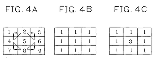
- Figures 4A-4C relate to a two-dimensional 3x3 filter.
- Figure 4A shows a filter window for a 3x3 filter.
- Figure 4B shows the weight factors for the 3x3 average filter, and
- Figure 4C shows the weight factors for the 3x3 weighted filter. It is allowable that the weight factor of the central point shown in Figure 4C is replaced by 2.
- the central point of the filter window is a point where an index value of the filter weight factor is "2".
- the average filter 70 and the weighted filter 80 are a sort of two-dimensional low-pass filters, the operation of which will be described as follows.
- the average filter 70 reads the pixel values necessary to calculate the filtered pixel value of the central point from the image store 10. Then, the average filter 70 calculates the filtered pixel values using the read pixel values and the weight factors shown in Figure 4B. The calculated filtered pixel value is used as an altered pixel value with respect to the central point.
- the weighted filter 80 performs a filtering operation based on the binary edge map information and the position data supplied from the filter determiner 60 with respect to the central point. The operation of the weighted filter 80 will be described below in more detail.
- the weighted filter 80 does not perform a filtering operation for the central point. If the edge point or the edge points are positioned in the 3x3 filter window excluding the central point, the weighted filter 80 performs a filtering operation using the weight factors shown in Figure 4C.
- the weight factors of the edge pixel and the outer neighbour pixels are set to zero.
- the signal adaptive filtered image data obtained by the average filter 70 and the weighted filter 80 are supplied to the image store 10.
- the image store 10 replaces a corresponding pixel value by using the image data supplied from the average filter 70 and the weighted filter 80. Accordingly, the image store 10 stores the signal adaptive filtered image data with respect to all pixels in the image applied from the prediction encoder 309. The image store 10 outputs image data to be used in the subtracter 301 and the adder 308 of Figure 1.
- the loop filtering method according to the present invention reduces the blocking effects and the ringing noise from the motion-compensated image, thereby providing an effect of improving the quality of the decompressed image.
Abstract
Description
Claims (11)
- A signal adaptive loop filtering method for a motion-compensated image, said signal adaptive loop filtering method comprising the steps of:(a) generating binary edge map information by globally thresholding and locally thresholding the motion-compressed image;(b) judging whether the binary edge map information within a filter window corresponding to respective pixels is either homogeneous area or edge area, by using the binary edge map information belonging to a predetermined size of the filter window;(c) generating a filtered pixel value corresponding to a respective pixel using the filter window which has predetermined first weight factors related to the homogeneous area, when the binary edge map information corresponding to the respective pixel is judged as the homogeneous area in said step (b);(d) altering predetermined second weight factors according to the binary edge map information corresponding to the respective pixel when the binary edge map information is judged as the edge area in said step (b); and(e) generating a filtered pixel value corresponding to the respective pixel, using the filter window which has the altered second weight factors in said step (d).
- The signal adaptive filtering method according to claim 1, wherein said step (a) comprises the steps of :(a1) generating a gradient image corresponding to the motion-compressed image;(a2) generating global edge map information which is composed of edge values corresponding to the respective pixels of the motion-compressed image, by comparing the predetermined first thresholding value with a gradient value corresponding to the respective pixels within the gradient image;(a3) generating local edge map information which is composed of edge values corresponding to the respective pixels of the motion-compressed image, by comparing gradient values within a predetermined size of individual blocks into which the motion-compressed image is divided, with a predetermined second thresholding value corresponding to the block; and(a4) logically summing an edge value in the global edge map information, and a corresponding edge value in the local edge map information, and generating binary edge map information.
- The signal adaptive filtering method according to claim 2, wherein said step (a3) calculates the second thresholding value corresponding to respective blocks using the following equation :
- The signal adaptive filtering method according to claim 3, wherein said step (a3) compares the gradient values corresponding to 6x6 pixels within a 8x8 block excluding boundary pixels within the 8x8 block with the corresponding second thresholding value.
- The signal adaptive filtering method according to claim 1, wherein the more the predetermined second weight factors move from the centre of the filter window to the boundary thereof, the less the predetermined second weight factors have.
- The signal adaptive filtering method according to claim 5, wherein said filter window has a 3x3 size.
- The signal adaptive filtering method according to claim 6, wherein said step (c) uses a filter window having the same magnitude of first weight factors.
- The signal adaptive filtering method according to claim 7, wherein the magnitude of said first weight factors is "1".
- The signal adaptive filtering method according to claim 8, wherein a second weight factor corresponding to said central point is "2" in magnitude, and second weight factors corresponding to the others thereof are "1".
- The signal adaptive filtering method according to claim 8, wherein a second weight factor corresponding to said central point is "3" in magnitude, and second weight factors corresponding to the others thereof are "1".
- The signal adaptive filtering method according to claim 8, wherein said step (d) comprises the step of resetting, as zero, second weight factors corresponding to positions put on a diagonal line and second weight factors corresponding to the outer neighbour of positions placed on the diagonal line, if the binary edge map information which corresponds to positions on the diagonal lines among the positions excluding the central point of the 3x3 sized filter window is represented as all edge points.
Applications Claiming Priority (2)
| Application Number | Priority Date | Filing Date | Title |
|---|---|---|---|
| KR1019960027399A KR100242637B1 (en) | 1996-07-06 | 1996-07-06 | Loop filtering method for reducing blocking effect and ringing noise of motion compensated image |
| KR9627399 | 1996-07-06 |
Publications (2)
| Publication Number | Publication Date |
|---|---|
| EP0817497A2 true EP0817497A2 (en) | 1998-01-07 |
| EP0817497A3 EP0817497A3 (en) | 1999-12-29 |
Family
ID=19465642
Family Applications (1)
| Application Number | Title | Priority Date | Filing Date |
|---|---|---|---|
| EP19960306903 Ceased EP0817497A3 (en) | 1996-07-06 | 1996-09-23 | Loop filtering method for reducing blocking effects and ringing noise of a motion-compensated image |
Country Status (5)
| Country | Link |
|---|---|
| US (1) | US5877813A (en) |
| EP (1) | EP0817497A3 (en) |
| JP (1) | JP2877768B2 (en) |
| KR (1) | KR100242637B1 (en) |
| CN (1) | CN1134152C (en) |
Cited By (14)
| Publication number | Priority date | Publication date | Assignee | Title |
|---|---|---|---|---|
| GB2323235A (en) * | 1997-03-10 | 1998-09-16 | Samsung Electronics Co Ltd | Removal of blocking effects using adaptive filtering |
| AU717480B2 (en) * | 1998-08-01 | 2000-03-30 | Korea Advanced Institute Of Science And Technology | Loop-filtering method for image data and apparatus therefor |
| US6259823B1 (en) | 1997-02-15 | 2001-07-10 | Samsung Electronics Co., Ltd. | Signal adaptive filtering method and signal adaptive filter for reducing blocking effect and ringing noise |
| FR2818862A1 (en) * | 2000-12-26 | 2002-06-28 | Koninkl Philips Electronics Nv | Compressed image data processing uses both gradient filtering and discontinuity detection for location of image blocks |
| FR2818863A1 (en) * | 2000-12-26 | 2002-06-28 | Koninkl Philips Electronics Nv | Received digital image processing method includes analysis of spatial activity values for pixel to detect and correct MPEG image errors |
| EP1333681A2 (en) * | 2002-01-31 | 2003-08-06 | Samsung Electronics Co., Ltd. | Filtering method and apparatus for reducing block artifacts or ringing noise |
| EP1473943A1 (en) * | 1998-03-05 | 2004-11-03 | Matsushita Electric Industrial Co., Ltd. | Image coding method, image coding and decoding method, image coding apparatus, and image recording and reproduction apparatus |
| WO2005034517A1 (en) * | 2003-09-17 | 2005-04-14 | Thomson Licensing S.A. | Adaptive reference picture generation |
| DE19730360B4 (en) * | 1997-01-29 | 2005-05-19 | Samsung Electronics Co., Ltd., Suwon | An image data filtering apparatus and method for reducing image data coding errors |
| WO2005088972A1 (en) * | 2004-03-11 | 2005-09-22 | Daeyang Foundation | Method, medium, and filter removing a blocking effect |
| WO2005112469A1 (en) * | 2004-05-18 | 2005-11-24 | Koninklijke Philips Electronics, N.V. | An algorithm for reducing artifacts in decoded video |
| WO2006066845A2 (en) * | 2004-12-22 | 2006-06-29 | Telefonaktiebolaget Lm Ericsson (Publ) | Adaptive image filter |
| US7620261B2 (en) | 2004-11-23 | 2009-11-17 | Stmicroelectronics Asia Pacific Pte. Ltd. | Edge adaptive filtering system for reducing artifacts and method |
| US7778480B2 (en) | 2004-11-23 | 2010-08-17 | Stmicroelectronics Asia Pacific Pte. Ltd. | Block filtering system for reducing artifacts and method |
Families Citing this family (41)
| Publication number | Priority date | Publication date | Assignee | Title |
|---|---|---|---|---|
| KR100243225B1 (en) * | 1997-07-16 | 2000-02-01 | 윤종용 | Signal adaptive filtering method for reducting blocking effect and ringing noise and filter thereof |
| CN1164116C (en) * | 1998-05-22 | 2004-08-25 | 松下电器产业株式会社 | Block noise detector and block noise eliminator |
| KR100308016B1 (en) | 1998-08-31 | 2001-10-19 | 구자홍 | Block and Ring Phenomenon Removal Method and Image Decoder in Compressed Coded Image |
| KR100335055B1 (en) | 1999-12-08 | 2002-05-02 | 구자홍 | Method of removal block effect and ringing effect of compressed video signal |
| US7203234B1 (en) | 2000-03-31 | 2007-04-10 | Sharp Laboratories Of America, Inc. | Method of directional filtering for post-processing compressed video |
| US7440635B2 (en) * | 2000-05-30 | 2008-10-21 | Sharp Laboratories Of America, Inc. | Method for removing ringing artifacts from locations near dominant edges of an image reconstructed after compression |
| US6707952B1 (en) | 2000-05-30 | 2004-03-16 | Sharp Laboratories Of America, Inc. | Method for removing ringing artifacts from locations near dominant edges of an image reconstructed after compression |
| JP4688279B2 (en) * | 2000-11-21 | 2011-05-25 | 富士通株式会社 | Method and apparatus for automatically setting spatial resolution of moving image |
| TW589870B (en) * | 2000-12-19 | 2004-06-01 | Pts Corp | Adaptive transforms |
| US7136538B2 (en) * | 2000-12-21 | 2006-11-14 | Matsushita Electric Industrial Co., Ltd. | Noise reducing apparatus and noise reducing method |
| JP2002218474A (en) * | 2001-01-24 | 2002-08-02 | Mitsubishi Electric Corp | Device for encoding image data |
| US6845180B2 (en) * | 2001-03-16 | 2005-01-18 | Sharp Laboratories Of America, Inc. | Predicting ringing artifacts in digital images |
| JP4066367B2 (en) * | 2003-11-28 | 2008-03-26 | ノーリツ鋼機株式会社 | Image noise removal method |
| CN1306826C (en) * | 2004-07-30 | 2007-03-21 | 联合信源数字音视频技术(北京)有限公司 | Loop filter based on multistage parallel pipeline mode |
| US7787703B2 (en) * | 2005-05-11 | 2010-08-31 | Xerox Corporation | Method and system for extending binary image data to contone image data |
| US8422546B2 (en) * | 2005-05-25 | 2013-04-16 | Microsoft Corporation | Adaptive video encoding using a perceptual model |
| KR100627615B1 (en) * | 2005-12-29 | 2006-09-25 | 엠텍비젼 주식회사 | Apparatus for removing color interpolation by using adjustable threshold |
| US20070237237A1 (en) * | 2006-04-07 | 2007-10-11 | Microsoft Corporation | Gradient slope detection for video compression |
| US8059721B2 (en) | 2006-04-07 | 2011-11-15 | Microsoft Corporation | Estimating sample-domain distortion in the transform domain with rounding compensation |
| US8503536B2 (en) * | 2006-04-07 | 2013-08-06 | Microsoft Corporation | Quantization adjustments for DC shift artifacts |
| US8130828B2 (en) * | 2006-04-07 | 2012-03-06 | Microsoft Corporation | Adjusting quantization to preserve non-zero AC coefficients |
| US7995649B2 (en) | 2006-04-07 | 2011-08-09 | Microsoft Corporation | Quantization adjustment based on texture level |
| US8711925B2 (en) | 2006-05-05 | 2014-04-29 | Microsoft Corporation | Flexible quantization |
| CN105392003A (en) * | 2006-11-08 | 2016-03-09 | 汤姆逊许可证公司 | Methods and apparatus for in-loop de-artifact filtering |
| KR100843100B1 (en) * | 2007-02-07 | 2008-07-03 | 삼성전자주식회사 | Method and apparatus for reducing block noises of digital image, and encoder/decoder using the same |
| US8238424B2 (en) * | 2007-02-09 | 2012-08-07 | Microsoft Corporation | Complexity-based adaptive preprocessing for multiple-pass video compression |
| US8498335B2 (en) * | 2007-03-26 | 2013-07-30 | Microsoft Corporation | Adaptive deadzone size adjustment in quantization |
| US20080240257A1 (en) * | 2007-03-26 | 2008-10-02 | Microsoft Corporation | Using quantization bias that accounts for relations between transform bins and quantization bins |
| US8243797B2 (en) | 2007-03-30 | 2012-08-14 | Microsoft Corporation | Regions of interest for quality adjustments |
| US8442337B2 (en) * | 2007-04-18 | 2013-05-14 | Microsoft Corporation | Encoding adjustments for animation content |
| US8331438B2 (en) * | 2007-06-05 | 2012-12-11 | Microsoft Corporation | Adaptive selection of picture-level quantization parameters for predicted video pictures |
| CN101094313B (en) * | 2007-07-25 | 2011-05-18 | 北京中星微电子有限公司 | Device and method for restraining noise |
| US8189933B2 (en) * | 2008-03-31 | 2012-05-29 | Microsoft Corporation | Classifying and controlling encoding quality for textured, dark smooth and smooth video content |
| US8897359B2 (en) | 2008-06-03 | 2014-11-25 | Microsoft Corporation | Adaptive quantization for enhancement layer video coding |
| TWI376645B (en) * | 2008-07-29 | 2012-11-11 | Sonix Technology Co Ltd | Image processing methof of noise reduction and apparatus thereof |
| CN101763630B (en) * | 2008-12-09 | 2011-12-28 | 新奥特(北京)视频技术有限公司 | Image expansion method based on weighted sum |
| US8437571B2 (en) * | 2009-04-30 | 2013-05-07 | Hewlett-Packard Development Company, L.P. | Method and system for adaptive context-embedded prediction |
| US8503528B2 (en) * | 2010-09-15 | 2013-08-06 | Google Inc. | System and method for encoding video using temporal filter |
| US9344729B1 (en) | 2012-07-11 | 2016-05-17 | Google Inc. | Selective prediction signal filtering |
| CN103888764B (en) * | 2014-03-14 | 2017-02-15 | 西安交通大学 | Self-adaptation compensation system and method for video compression distortion |
| US10102613B2 (en) | 2014-09-25 | 2018-10-16 | Google Llc | Frequency-domain denoising |
Family Cites Families (12)
| Publication number | Priority date | Publication date | Assignee | Title |
|---|---|---|---|---|
| US5027422A (en) * | 1988-08-29 | 1991-06-25 | Raytheon Company | Confirmed boundary pattern matching |
| JPH03127580A (en) * | 1989-10-13 | 1991-05-30 | Matsushita Electric Ind Co Ltd | Movement compensation inter-frame coder |
| JP3338460B2 (en) * | 1991-05-09 | 2002-10-28 | ソニー株式会社 | Video signal encoding device and video signal encoding method |
| JPH05183888A (en) * | 1991-12-27 | 1993-07-23 | Mitsubishi Electric Corp | Information source encoder |
| US5367385A (en) * | 1992-05-07 | 1994-11-22 | Picturetel Corporation | Method and apparatus for processing block coded image data to reduce boundary artifacts between adjacent image blocks |
| JP2624087B2 (en) * | 1992-07-02 | 1997-06-25 | 松下電器産業株式会社 | Video signal decoding method |
| DE4305911A1 (en) * | 1993-02-26 | 1994-09-01 | Philips Patentverwaltung | Video decoder with a control unit |
| US5359676A (en) * | 1993-07-19 | 1994-10-25 | Xerox Corporation | Decompression of standard ADCT-compressed document images |
| US5512956A (en) * | 1994-02-04 | 1996-04-30 | At&T Corp. | Adaptive spatial-temporal postprocessing for low bit-rate coded image sequences |
| US5461422A (en) * | 1994-05-23 | 1995-10-24 | Industrial Technology Research Institute | Quantizer with automatic pre-threshold |
| JP3686695B2 (en) * | 1994-10-20 | 2005-08-24 | オリンパス株式会社 | Image processing device |
| KR100242636B1 (en) * | 1996-03-23 | 2000-02-01 | 윤종용 | Signal adaptive post processing system for reducing blocking effect and ringing noise |
-
1996
- 1996-07-06 KR KR1019960027399A patent/KR100242637B1/en not_active IP Right Cessation
- 1996-09-23 EP EP19960306903 patent/EP0817497A3/en not_active Ceased
- 1996-09-24 CN CNB961220597A patent/CN1134152C/en not_active Expired - Fee Related
- 1996-09-24 JP JP25192596A patent/JP2877768B2/en not_active Expired - Fee Related
- 1996-10-18 US US08/733,449 patent/US5877813A/en not_active Expired - Lifetime
Non-Patent Citations (1)
| Title |
|---|
| None |
Cited By (46)
| Publication number | Priority date | Publication date | Assignee | Title |
|---|---|---|---|---|
| DE19730360B4 (en) * | 1997-01-29 | 2005-05-19 | Samsung Electronics Co., Ltd., Suwon | An image data filtering apparatus and method for reducing image data coding errors |
| US6259823B1 (en) | 1997-02-15 | 2001-07-10 | Samsung Electronics Co., Ltd. | Signal adaptive filtering method and signal adaptive filter for reducing blocking effect and ringing noise |
| GB2323235A (en) * | 1997-03-10 | 1998-09-16 | Samsung Electronics Co Ltd | Removal of blocking effects using adaptive filtering |
| DE19809707C2 (en) * | 1997-03-10 | 2003-07-17 | Samsung Electronics Co Ltd | Adaptive filter for a one-dimensional signal for reducing the block effect and filtering method |
| GB2323235B (en) * | 1997-03-10 | 1999-01-13 | Samsung Electronics Co Ltd | One-dimensional signal adaptive filter for reducing blocking effect and filtering method |
| EP1473943A1 (en) * | 1998-03-05 | 2004-11-03 | Matsushita Electric Industrial Co., Ltd. | Image coding method, image coding and decoding method, image coding apparatus, and image recording and reproduction apparatus |
| US6941022B2 (en) | 1998-03-05 | 2005-09-06 | Matsushita Electric Industrial Co., Ltd. | Image coding method, image coding and decoding method, image coding apparatus, and image recording and reproduction apparatus |
| AU717480B2 (en) * | 1998-08-01 | 2000-03-30 | Korea Advanced Institute Of Science And Technology | Loop-filtering method for image data and apparatus therefor |
| FR2818862A1 (en) * | 2000-12-26 | 2002-06-28 | Koninkl Philips Electronics Nv | Compressed image data processing uses both gradient filtering and discontinuity detection for location of image blocks |
| FR2818863A1 (en) * | 2000-12-26 | 2002-06-28 | Koninkl Philips Electronics Nv | Received digital image processing method includes analysis of spatial activity values for pixel to detect and correct MPEG image errors |
| EP1223763A1 (en) * | 2000-12-26 | 2002-07-17 | Koninklijke Philips Electronics N.V. | Image data processing method |
| EP1223764A1 (en) * | 2000-12-26 | 2002-07-17 | Koninklijke Philips Electronics N.V. | Image data processing method |
| US6920252B2 (en) | 2000-12-26 | 2005-07-19 | Koninklijke Philips Electronics N.V. | Data processing method |
| US6950562B2 (en) | 2000-12-26 | 2005-09-27 | Koninklijke Philips Electronics N.V. | Data processing method |
| US7630437B2 (en) | 2002-01-31 | 2009-12-08 | Samsung Electronics Co., Ltd. | Filtering method for removing block artifacts and/or ringing noise and apparatus therefor |
| US8699568B2 (en) | 2002-01-31 | 2014-04-15 | Samsung Electronics Co., Ltd. | Filtering method for removing block artifacts and/or ringing noise and apparatus therefor |
| US9538201B2 (en) | 2002-01-31 | 2017-01-03 | Samsung Electronics Co., Ltd. | Filtering method for removing block artifacts and/or ringing noise and apparatus therefor |
| EP1333681A3 (en) * | 2002-01-31 | 2004-12-08 | Samsung Electronics Co., Ltd. | Filtering method and apparatus for reducing block artifacts or ringing noise |
| US9538203B2 (en) | 2002-01-31 | 2017-01-03 | Samsung Electronics Co., Ltd. | Filtering method for removing block artifacts and/or ringing noise and apparatus therefor |
| US9538202B2 (en) | 2002-01-31 | 2017-01-03 | Samsung Electronics Co., Ltd. | Filtering method for removing block artifacts and/or ringing noise and apparatus therefor |
| US9538204B2 (en) | 2002-01-31 | 2017-01-03 | Samsung Electronics Co., Ltd. | Filtering method for removing block artifacts and/or ringing noise and apparatus therefor |
| US9532078B2 (en) | 2002-01-31 | 2016-12-27 | Samsung Electronics Co., Ltd. | Filtering method for removing block artifacts and/or ringing noise and apparatus therefor |
| EP1333681A2 (en) * | 2002-01-31 | 2003-08-06 | Samsung Electronics Co., Ltd. | Filtering method and apparatus for reducing block artifacts or ringing noise |
| US9532077B2 (en) | 2002-01-31 | 2016-12-27 | Samsung Electronics Co., Ltd. | Filtering method for removing block artifacts and/or ringing noise and apparatus therefor |
| US9532079B2 (en) | 2002-01-31 | 2016-12-27 | Samsung Electronics Co., Ltd. | Filtering method for removing block artifacts and/or ringing noise and apparatus therefor |
| US8160138B2 (en) | 2002-01-31 | 2012-04-17 | Samsung Electronics Co., Ltd. | Filtering method for removing block artifacts and/or ringing noise and apparatus therefor |
| US8208749B2 (en) | 2002-01-31 | 2012-06-26 | Samsung Electronics Co., Ltd. | Filtering method for removing block artifacts and/or ringing noise and apparatus therefor |
| US8290039B2 (en) | 2002-01-31 | 2012-10-16 | Samsung Electronics Co., Ltd. | Filtering method for removing block artifacts and/or ringing noise and apparatus therefor |
| US8457438B2 (en) | 2002-01-31 | 2013-06-04 | Samsung Electronics Co., Ltd. | Filtering method for removing block artifacts and/or ringing noise and apparatus therefor |
| US9467716B2 (en) | 2002-01-31 | 2016-10-11 | Samsung Electronics Co., Ltd. | Filtering method for removing block artifacts and/or ringing noise and apparatus therefor |
| US9060105B2 (en) | 2002-01-31 | 2015-06-16 | Samsung Electronics Co., Ltd. | Filtering method for removing block artifacts and/or ringing noise and apparatus therefor |
| EP2894856A1 (en) * | 2002-01-31 | 2015-07-15 | Samsung Electronics Co., Ltd | Filtering method and apparatus for reducing block artifacts or ringing noise |
| EP2899977A1 (en) * | 2002-01-31 | 2015-07-29 | Samsung Electronics Co., Ltd | Filtering method and apparatus for reducing block artifacts or ringing noise |
| US9161059B2 (en) | 2002-01-31 | 2015-10-13 | Samsung Electronics Co., Ltd. | Filtering method for removing block artifacts and/or ringing noise and apparatus therefor |
| US9258574B2 (en) | 2002-01-31 | 2016-02-09 | Samsung Electronics Co., Ltd. | Filtering method for removing block artifacts and/or ringing noise and apparatus therefor |
| US9467717B2 (en) | 2002-01-31 | 2016-10-11 | Samsung Electronics Co., Ltd. | Filtering method for removing block artifacts and/or ringing noise and apparatus therefor |
| US9467714B2 (en) | 2002-01-31 | 2016-10-11 | Samsung Electronics Co., Ltd. | Filtering method for removing block artifacts and/or ringing noise and apparatus therefor |
| US9467715B2 (en) | 2002-01-31 | 2016-10-11 | Samsung Electronics Co., Ltd. | Filtering method for removing block artifacts and/or ringing noise and apparatus therefor |
| WO2005034517A1 (en) * | 2003-09-17 | 2005-04-14 | Thomson Licensing S.A. | Adaptive reference picture generation |
| US8094711B2 (en) | 2003-09-17 | 2012-01-10 | Thomson Licensing | Adaptive reference picture generation |
| WO2005088972A1 (en) * | 2004-03-11 | 2005-09-22 | Daeyang Foundation | Method, medium, and filter removing a blocking effect |
| WO2005112469A1 (en) * | 2004-05-18 | 2005-11-24 | Koninklijke Philips Electronics, N.V. | An algorithm for reducing artifacts in decoded video |
| US7778480B2 (en) | 2004-11-23 | 2010-08-17 | Stmicroelectronics Asia Pacific Pte. Ltd. | Block filtering system for reducing artifacts and method |
| US7620261B2 (en) | 2004-11-23 | 2009-11-17 | Stmicroelectronics Asia Pacific Pte. Ltd. | Edge adaptive filtering system for reducing artifacts and method |
| WO2006066845A3 (en) * | 2004-12-22 | 2007-01-18 | Ericsson Telefon Ab L M | Adaptive image filter |
| WO2006066845A2 (en) * | 2004-12-22 | 2006-06-29 | Telefonaktiebolaget Lm Ericsson (Publ) | Adaptive image filter |
Also Published As
| Publication number | Publication date |
|---|---|
| CN1170318A (en) | 1998-01-14 |
| KR980013443A (en) | 1998-04-30 |
| KR100242637B1 (en) | 2000-02-01 |
| US5877813A (en) | 1999-03-02 |
| CN1134152C (en) | 2004-01-07 |
| JPH1066090A (en) | 1998-03-06 |
| JP2877768B2 (en) | 1999-03-31 |
| EP0817497A3 (en) | 1999-12-29 |
Similar Documents
| Publication | Publication Date | Title |
|---|---|---|
| EP0817497A2 (en) | Loop filtering method for reducing blocking effects and ringing noise of a motion-compensated image | |
| EP0797349B1 (en) | Signal adaptive postprocessing system for reducing blocking effects and ringing noise | |
| US5974197A (en) | Loop filter and loop filtering method | |
| KR100219628B1 (en) | Signal adaptive filtering method and signal adaptive filter | |
| US6226050B1 (en) | Signal adaptive filtering method for reducing ringing noise and signal adaptive filter | |
| Park et al. | A postprocessing method for reducing quantization effects in low bit-rate moving picture coding | |
| EP0723375B1 (en) | Post-processing device and method for eliminating blocking artifacts from decompressed images | |
| US6983079B2 (en) | Reducing blocking and ringing artifacts in low-bit-rate coding | |
| KR100797807B1 (en) | Method of coding artefacts reduction | |
| Lee et al. | Loop filtering and post-filtering for low-bit-rates moving picture coding | |
| US6167164A (en) | One-dimensional signal adaptive filter for reducing blocking effect and filtering method | |
| KR100269125B1 (en) | Image post processing method and apparatus for reducing quantization effect | |
| Tai et al. | Deblocking filter for low bit rate MPEG-4 video | |
| EP1408699A1 (en) | Signal adaptive filtering method, signal adaptive filter and computer readable medium for storing program therefor | |
| JPH08186714A (en) | Noise removal of picture data and its device | |
| US20080181495A1 (en) | Reduction of color bleeding effects in a digitally processed image | |
| US5787207A (en) | Method and apparatus for minimizing blockiness in reconstructed images | |
| JP2926638B2 (en) | Loop filter and loop filtering method | |
| JPH0856357A (en) | Image processor |
Legal Events
| Date | Code | Title | Description |
|---|---|---|---|
| PUAI | Public reference made under article 153(3) epc to a published international application that has entered the european phase |
Free format text: ORIGINAL CODE: 0009012 |
|
| 17P | Request for examination filed |
Effective date: 19961015 |
|
| AK | Designated contracting states |
Kind code of ref document: A2 Designated state(s): DE FR GB |
|
| PUAL | Search report despatched |
Free format text: ORIGINAL CODE: 0009013 |
|
| AK | Designated contracting states |
Kind code of ref document: A3 Designated state(s): DE FR GB |
|
| RIC1 | Information provided on ipc code assigned before grant |
Free format text: 6H 04N 1/41 A, 6H 04N 7/30 B, 6H 04N 7/50 B |
|
| AKX | Designation fees paid |
Free format text: DE FR GB |
|
| 17Q | First examination report despatched |
Effective date: 20010314 |
|
| STAA | Information on the status of an ep patent application or granted ep patent |
Free format text: STATUS: THE APPLICATION HAS BEEN REFUSED |
|
| 18R | Application refused |
Effective date: 20030623 |