EP0817459A2 - Electrophotographic image-forming apparatus - Google Patents
Electrophotographic image-forming apparatus Download PDFInfo
- Publication number
- EP0817459A2 EP0817459A2 EP97110560A EP97110560A EP0817459A2 EP 0817459 A2 EP0817459 A2 EP 0817459A2 EP 97110560 A EP97110560 A EP 97110560A EP 97110560 A EP97110560 A EP 97110560A EP 0817459 A2 EP0817459 A2 EP 0817459A2
- Authority
- EP
- European Patent Office
- Prior art keywords
- image
- forming apparatus
- document
- cover
- original document
- Prior art date
- Legal status (The legal status is an assumption and is not a legal conclusion. Google has not performed a legal analysis and makes no representation as to the accuracy of the status listed.)
- Granted
Links
- 238000004140 cleaning Methods 0.000 claims description 8
- 239000000463 material Substances 0.000 claims description 3
- 238000000034 method Methods 0.000 description 25
- 230000008569 process Effects 0.000 description 25
- 238000012546 transfer Methods 0.000 description 25
- 238000010276 construction Methods 0.000 description 9
- 238000000926 separation method Methods 0.000 description 9
- 230000015572 biosynthetic process Effects 0.000 description 7
- 230000001105 regulatory effect Effects 0.000 description 4
- 230000004044 response Effects 0.000 description 4
- 238000011144 upstream manufacturing Methods 0.000 description 4
- 230000000977 initiatory effect Effects 0.000 description 3
- 230000002452 interceptive effect Effects 0.000 description 3
- 230000007246 mechanism Effects 0.000 description 3
- 230000002441 reversible effect Effects 0.000 description 3
- 239000000919 ceramic Substances 0.000 description 2
- 238000004519 manufacturing process Methods 0.000 description 2
- 238000012986 modification Methods 0.000 description 2
- 230000004048 modification Effects 0.000 description 2
- 230000009471 action Effects 0.000 description 1
- 210000000078 claw Anatomy 0.000 description 1
- 230000000881 depressing effect Effects 0.000 description 1
- 238000011161 development Methods 0.000 description 1
- 230000005484 gravity Effects 0.000 description 1
- 230000006872 improvement Effects 0.000 description 1
- 238000009434 installation Methods 0.000 description 1
- 238000012423 maintenance Methods 0.000 description 1
- 239000002184 metal Substances 0.000 description 1
- 238000012545 processing Methods 0.000 description 1
- 230000009467 reduction Effects 0.000 description 1
- 230000000717 retained effect Effects 0.000 description 1
- 239000004065 semiconductor Substances 0.000 description 1
- 230000001360 synchronised effect Effects 0.000 description 1
- 238000013024 troubleshooting Methods 0.000 description 1
- 239000002699 waste material Substances 0.000 description 1
Images


Classifications
-
- H—ELECTRICITY
- H04—ELECTRIC COMMUNICATION TECHNIQUE
- H04N—PICTORIAL COMMUNICATION, e.g. TELEVISION
- H04N1/00—Scanning, transmission or reproduction of documents or the like, e.g. facsimile transmission; Details thereof
- H04N1/00519—Constructional details not otherwise provided for, e.g. housings, covers
- H04N1/00551—Top covers or the like
-
- H—ELECTRICITY
- H04—ELECTRIC COMMUNICATION TECHNIQUE
- H04N—PICTORIAL COMMUNICATION, e.g. TELEVISION
- H04N1/00—Scanning, transmission or reproduction of documents or the like, e.g. facsimile transmission; Details thereof
- H04N1/00519—Constructional details not otherwise provided for, e.g. housings, covers
- H04N1/00525—Providing a more compact apparatus, e.g. sheet discharge tray in cover
Definitions
- the present invention relates to a multi-function image-forming apparatus integrally constructed by so-called image-forming means and document-reading means, such as a printer with a function of an image scanner or a printer with a function of a facsimile, and capable of performing multiple functions (for example, functions of a printer, a scanner, a facsimile, a copier or the like).
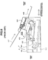
- the apparatus body 101 of the laser printer comprises a sheet-feeding cassette 102 for receiving recording papers before subjected to image formation, a process cartridge 103 into which a photosensitive drum, a charging device, a developing device, a cleaner or the like are integrally incorporated, a cartridge cover 104 adapted to be opened or closed when the process cartridge 103 is mounted to or removed from the apparatus body 101, and a sheet-delivery tray 105 for receiving therein the recording papers on which desired image has been formed.
- the sheet-feeding cassette 102 is pulled out of the apparatus body 101 rightward (frontward) when viewed in Fig. 8.
- a cartridge cover 104 is opened in the upward direction indicated by an arrow A in Fig. 8 to remove the process cartridge 103 from the apparatus body 101.
- the image scanner 106 which is adapted to read an image from an original document is mounted to an upper side of the apparatus body 101.
- the image scanner 106 is provided, on rear and front sides thereof, with a sheet-feeding tray 107 on which the original document is set, and a delivery tray 108 for receiving the original document from which the image has been read out, respectively.
- the advancing direction of the original document is indicated by a solid line arrow, while the advancing direction of the recording paper is indicated by a dotted line arrow.
- the afore-mentioned conventional apparatus has posed the following problems. That is, when the cartridge cover 104 is opened to remove the process cartridge 103 from the apparatus body 101, there arise a problem that the sheet-feeding tray 107 hanging over the cartridge cover 104 inhibits the user's access thereto, which makes it difficult to remove the process cartridge 103.
- the printer with a function for reading out an image from the original document requires not only the sheet-feeding tray and the delivery tray for the recording paper but also those for the original document. As the size of the apparatus body is reduced, it becomes more important how these trays are arranged in the apparatus.
- the present invention has been made to solve the afore-mentioned problems. Accordingly, it is an object of the present invention to provide an electrophotographic image-forming apparatus which is small in size and excellent in operability.
- an electrophotographic image-forming apparatus which comprises a main assembly; an image-forming means for forming an image on a recording medium, which is mounted to an interior of the main assembly such that at least a part of the image-forming means can be removed therefrom; a cover for opening and closing the interior of the main assembly such that when the cover is opened, at least a part of the image-forming means is removable from the main assembly; and an original document-reading unit for reading an image from an original document, which is mounted to the cover so as to be moved together with the cover.
- the document-reading unit is mounted to the cover which is opened and closed so as to attach and detach at least a part of the image-forming means, the cover and the document-reading unit are prevented from interfering with each other. This allows smooth attaching and detaching operations of the part of the image-forming means.
- the construction of the document-reading unit can be varied according to aimed applications, thereby permitting easy maintenance of the image-forming apparatus.
- the delivery tray for receiving the recording paper on which desired image has been formed by the afore-mentioned image-forming means is integrally formed with the cover, the cover and the delivery tray can be prevented from interfering with each other.
- the document-reading unit is mounted to a front surface of the afore-mentioned image-forming apparatus, the user can have access to both the recording paper and the original document from the same front position.
- the document-reading unit is arranged on a front side of the delivery tray, the original document can be readily recognized by the user, so that the user can be prevented from erroneously feeding the original document, e.g., setting sides or surfaces thereof upside down.
- the afore-mentioned image-forming apparatus may further comprises a first sheet-feeding tray for receiving the recording medium to be supplied to the image-forming means, a delivery tray for receiving the recording medium on which desired image is formed by the image-forming means, and a second sheet-feeding tray for receiving the original document to be supplied to the document-reading unit, which trays hold the recording medium or the original document in the direction approximately perpendicular to a bottom surface of the apparatus.
- the trays and the cover can be prevented from interfering with each other in the horizontal direction, which can permit the main assembly to be minimized.
- the part of the aforementioned image-forming means which can be removed from the main assembly may be at least one element selected from an electrophotographic photosensitive body, a charging device for electrifying the electrophotographic photosensitive body and a cleaner for cleaning the electrophotographic photosensitive body.
- an image-forming apparatus having a function for reading out an image from an original document, which comprises an image-forming means for forming an image on a recording medium; a document-reading means for reading out the image from the original document; and a common delivery tray for receiving both the recording medium on which desired image has been formed by the image-forming means and the original document from which the image is read out by the document-reading means such that image-bearing surfaces of the recording medium and original document face in different directions from each other.
- the common delivery tray are provided for both the recording medium and the original document, it is possible to achieve saving of space therefor.
- the recording medium and the original document is received in the common delivery tray such that the image-bearing surface of the recording medium faces in the reverse direction to that of the original document, the user can be prevented from confusing the recording medium with the original document and erroneously handling these materials.
- an image-forming apparatus comprising a cover for opening and closing an interior of the main assembly such that when the cover is opened, at least a part of the afore-mentioned image-forming means can be removed from the main assembly, wherein the reading unit for the original document is fitted onto the cover so as to be movable together with the cover.
- a laser beam printer M equipped with a process cartridge as an example of an electrophotographic image-forming apparatus according to the present invention.
- the right and left sides of the printer illustrated throughout the accompanying drawings correspond to rear and front sides thereof, respectively.
- the rear and front sides of the printer correspond to upstream and downstream sides thereof, respectively, relative to the conveying direction of the recording medium P.
- the recording medium P on which desired image is to be formed there may be used special papers such as cartons or envelopes, or sheet materials other than papers, e.g., OHP films as well as ordinary plain papers.
- special papers such as cartons or envelopes, or sheet materials other than papers, e.g., OHP films as well as ordinary plain papers.
- the ordinary plain papers recording paper
- the recording medium P are used as an example of the recording medium P.
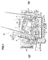
- printer M a general construction of the laser beam printer M (hereinafter referred to merely as "printer M") is described below.
- the printer M comprises a printer body 1 as an image-forming means (hereinafter referred to merely as "body”; incidentally, in the following descriptions, it is intended that the "body” involves not only a frame member constituting an exterior of the printer M but also a frame member constituting an interior thereof), and an image-reading unit 90 which is an image-reading means using a close-contact type contact image sensor as a read-out element.
- the body 1 is provided on a rear side thereof with a first supporting means 10 for supporting the recording paper P before subjected to the image formation in an upright state, and on a front side thereof with a second supporting means 20 for also supporting the recording paper P after subjected to the image formation in an upright state.
- the lower end 10a of the first supporting means 10 is connected with the lower end 20a of the second supporting means 20 through a conveying path 30 extending from the rear side of the body 1 toward the front side thereof, so that U-shaped conveying path (hereinafter referred to merely as "vertical U-shaped path”) is constructed as a whole.
- the printer M further comprises a process cartridge 40 which is disposed immediately above the conveying path 30 and into which a drum-shaped electrophotographic photosensitive body 41 (hereinafter referred to merely as "photosensitive drum") or the like are integrally incorporated, an information light-irradiating means 50 disposed above the process cartridge 40, a transfer means 60 disposed underneath a mid-portion of the conveying path 30 in an opposed relation to the photosensitive drum 41, and a fixing means 70 disposed immediately below the lower end of the second supporting means 20 on the downward side of the conveying path 30.
- a process cartridge 40 which is disposed immediately above the conveying path 30 and into which a drum-shaped electrophotographic photosensitive body 41 (hereinafter referred to merely as "photosensitive drum”) or the like are integrally incorporated
- an information light-irradiating means 50 disposed above the process cartridge 40
- a transfer means 60 disposed underneath a mid-portion of the conveying path 30 in an opposed relation to the photosensitive drum 41
- a fixing means 70 disposed immediately
- the process cartridge 40 and the information light-irradiating means 50 are arranged inside the vertical U-shaped path, while the transfer means 60 is arranged outside the vertical U-shaped path, Further, the fixing means 70 are so arranged as to extend across the vertical U-shaped path on the downstream side of the conveying path 30.
- the charging device 42, the information light-irradiating means 50 and the developing means 43 cooperate with each other to form a toner image on the photosensitive drum 41.
- the recording paper P is supplied in a face-down manner from the first supporting means 10 and transported through the upstream side of the conveying path 30 to the photosensitive drum 41 where the toner image formed thereon is transferred onto the recording paper P by the transfer means 60.
- the recording paper P having the transferred toner image thereon is sent to the fixing means 70 where the toner image is affixed on a surface thereof, and then delivered upwardly to the second supporting means 20 by which the recording paper P is supported in approximately upright state.
- the first supporting means 10 is provided on the rear side of the body 1 and comprises, sequentially from the bottom, an abutting member 11, a tip-supporting member 12 and a sheet-feeding tray 13.
- the abutting member 11 abuts against the forward tip end of the recording paper P from below to support the weight thereof.
- the tip-supporting member 12 is supported by the body 1 so as to be pivotable around a shaft 12a in the fore-and-aft direction, and biased toward the front side by a spring 12b disposed on a rear surface of a lower end portion thereof.
- the forwardly-biased tip-supporting member 12 is retained at a rearwardly retarded position by the action of a cam member (not shown) before feeding of the recording paper P, and moved only upon the feeding of the recording paper P by the rotation of the cam member to thereby urge the recording paper P rested thereon in the forward direction.
- the sheet-feeding tray 13 is so arranged as to project vertically upwardly from a rear end of an upper surface of the body 1.
- the sheet-feeding tray 13 supports intermediate and rear-end portions of the recording paper P from a rear surface side thereof such that the recording paper P before subjected to the image formation is supported as a whole in a flatly upright state.
- Two movable regulating plates 13L and 13R for regulating the position of the recording paper P in the left-to-right direction thereof (when viewed in the front-to-rear direction of the printer) is disposed on a front side of the sheet-feeding tray 13.
- the sheet-feeding tray 13 is provided on an upper end thereof with an extension guide 13a which can be upwardly pulled out of the sheet-feeding tray so as to stably support the recording paper P having a larger length in the conveying direction.
- the second supporting means 20 is disposed on the front portion of the body 1 opposite to the first supporting means 10 provided on the rear portion of the body 1.
- the second supporting means 20 is mounted to the openable exterior cover 2 constituting a part of the body 1, and comprises, sequentially from the bottom, an abutting member (rear end-regulating surface) 21, a delivery tray (stacking surface) 22 and an extension tray 23.
- the recording paper P after subjected to the image formation is supported at its rear end from below by the abutting member 21.
- the rear half portion of the recording paper P is supported from a back surface side thereof by the delivery tray 22 while the front half portion of the recording paper P is supported from a back surface side thereof by the extension tray 23.
- the extension tray 23 is liftably supported in the delivery tray 22 so as to be pulled out upwardly therefrom.
- the recording paper P after subjected to the image formation can be supported in a flatly upright state by the extension tray 23 pulled out and the delivery tray 22.
- the conveying path 30 connects the lower end 10a of the first supporting means 10 with the lower end 20a of the second supporting means 20 and forms a passage extending from the rear side to the front side of the body 1 for conveying the recording paper P.
- the conveying path 30 comprises, sequentially from the rear side (upstream side) to the front side (downstream side), a separation pad 31, a pre-transfer guide 32, a post-transfer guide 33, and a reversing guide 34 disposed on a downstream side of the fixing means 70. Further, a feed roller 35 is disposed on an inclined upper side of the separation pad 31, and a conveying roller 36 is disposed below the feed roller 35.
- the feed roller 35 has an outer circumferential surface which is formed eccentrically to a shaft 35a.
- the feed roller 35 cooperates with the conveying roller 36 to transport the recording paper P while preventing two or more recording papers P from being simultaneously fed in double sheet feeding manner between the feed roller 35 and the separation pad 31.
- the pre-transfer guide 32 extends in approximately horizontal direction and serves for guiding the recording paper P between an upper surface thereof and a lower surface 40a of the process cartridge 40 arranged thereabove and then introducing the recording paper P into a transfer section defined between the photosensitive drum 41 and a transfer roller 61 of the transfer means 60.
- the post-transfer guide 33 is formed into a moderate convex shape. After the toner image is transferred, the recording paper P is conveyed by the post-transfer guide 33 into a fixing section defined between a fixing film 74 of the fixing means 70 and a pressure roller 75.
- the reversing guide 34 is of a moderately curved shape and disposed between F/U (face-up) delivery roller pair 37 located immediately downstream of the fixing means 70 and F/D (face-down) delivery roller pair 38 located above the F/U roller pair 37 so as to upwardly guide the recording paper P on which the toner image has been fixed, toward the second supporting means 20.
- the reversing guide 34 is integrally formed with the afore-mentioned exterior cover 2.
- the process cartridge 40 has such a construction that the photosensitive drum 41, a charging roller (charging means) 42, a developing device (developing means) 43 and a cleaning device (cleaning means) 44 are integrally incorporated into a cartridge casing 45, and is detachably mounted to the body 1.
- the photosensitive drum 41 is constructed by a drum-shaped electrophotographic photosensitive body as described above, and driven by a driving mechanism including a motor 81 as a driving source which is mounted in the body 1.
- the charging roller 42 is disposed so as to be brought into contact with a surface of the photosensitive drum 41, and rotatably driven in association with the rotation of the photosensitive drum 41.
- the charging roller 42 is applied with a charging voltage of superimposed D.C. and A.C. currents supplied from a board 80 mounted in the body 1. Therefore, the charging roller 41 can electrify a surface of the photosensitive drum 41 uniformly when the drum is rotated.
- the developing device 43 comprises a toner receptacle 43a for storing a toner and a developing roller 43b.
- the developing roller 43b incorporates a magnet therein so that the toner is carried on a surface of the developer roller upon the rotation thereof.
- the thickness of the toner carried on the surface of the developer roller is regulated by a regulating blade 43c, upon which the toner is electrostatically charged.
- the toner is attached onto an electrostatic latent image formed on the photosensitive drum 41 by an information light-irradiating means 50 described in detail hereinafter to form a toner image thereon.
- the developer device 43 comprises the toner receptacle 43a disposed in an upper portion thereof and the developer roller 43b disposed in a lower portion thereof, the toner within the toner receptacle 43a is permitted to be automatically fallen by gravity on the developing roller 43b. Accordingly, it is not necessary to provide a special mechanism for transporting the toner within the toner receptacle 43a toward the developing roller 43b, for example, an agitating member or the like, whereby it is possible to simplify the construction of the process cartridge 40.
- the cleaning device 44 comprises a cleaning blade 44a which is brought into slide contact with the surface of the photosensitive drum 41 whose toner image has been transferred to the recording medium, to remove a residual toner therefrom, and a cleaning container 44b into which the waste toner removed is recovered.
- the cartridge casing 45 is formed on an upper portion thereof with a hole 45a for permitting the photosensitive drum to be exposed to light passing therethrough. Incidentally, attaching and detaching operations of the process cartridge 40 to the body 1 are described hereinafter.
- the information light-irradiating means 50 is adapted to irradiate light through the afore-mentioned hole 45a onto the surface of the photosensitive drum 41, and disposed as a whole above the process cartridge 40.
- the information light-irradiating means 50 comprises a semiconductor laser 55 for emitting a laser beam in response to a picture signal, a polygon mirror 51 which is rotated to reflect the laser beam, a motor 52 for rotatably driving the polygon mirror 51, a lens 53 and a reflecting mirror 54.
- the electrostatic latent image corresponding to the picture signal is formed on the surface of the photosensitive drum 41.
- the afore-mentioned process cartridge 40 and information light-irradiating means 50 are compactly arranged within a space defined by the rear first supporting means 10, the front second supporting means 20 and the lower conveying path 30, i.e., the space located inside the vertical U-shaped path.
- the transfer means 60 is disposed under the conveying path 30 and comprises a transfer roller 61 which is brought into contact with the photosensitive drum 41 from below and the transfer roller 61 cooperates with the photosensitive drum 41 to define a transfer section therebetween.
- the transfer roller 61 is supported at opposite right and left ends of a core metal 61 by spring-biased bearings. This allows the transfer roller to be pressed against the surface of the photosensitive drum 41 with a predetermined depressing force.
- the transfer voltage having a reverse polarity to that of the toner image is applied to the transfer roller 61 by the board 80 . This permits the toner image on the photosensitive drum 41 to be transferred to the surface of the recording paper P passing through the transfer section.
- the fixing means 70 comprises a ceramic heater 72 supported on the body 1 through a spring, a fixing film 74 mounted in the form of an endless belt around an outer circumferential surface of a guide 73, and a pressure roller 75 abutting against the fixing film 74 from below to thereby define a fixing section between the pressure roller 75 and the fixing film 74.
- the ceramic heater 72 and the fixing film 74 have a low heat capacity, and therefore can be heated to a temperature required for fixing, shortly after energizing thereof. This prevents unnecessary heat from being irradiated from the fixing means 70.
- the fixing means 70 is adapted such that when the recording paper P, onto which the toner image has been transferred in the transfer section located on the upstream side thereof, passes over the fixing section, the non-fixed toner image carried by the recording paper P is heat-fused and fixed on the surface of the recording paper P.
- the exterior cover 2 has a combined function as a member for closing the front surface of the body 1 and as the afore-mentioned second supporting means 20, and is supported by a hinge 2a so as to be pivotable therearound in the direction of an arrow D. As shown in Fig. 2, when the exterior cover 2 is opened, a large access opening 1a is present on the front surface of the body 1 so that the process cartridge 40 is readily mounted to the interior of the body 1 therethrough.
- the process cartridge 40 mounted is readily removed from the body 1 in a similar manner. Further, when the process cartridge 40 is removed, the portion of the conveying path 30 ranging from the sheet-feeding section to the fixing section is exposed to outside, thereby facilitating removal of jammed recording papers P or the like.
- the recording papers P are set in an upright state in the first supporting means 10. While the photosensitive drum 41 in the process cartridge is rotatably driven, the surface of the photosensitive drum 41 is electrically charged to uniform potential having, for example, a negative polarity by the charging roller 42. The uniformly charged surface of the photosensitive drum 41 is then exposed to light irradiated from the information light-irradiating means 50. The information light-irradiating means 50 emits a laser beam in response to a picture signal to irradiate the surface of the photosensitive drum 41. The irradiated portion of the surface of the photosensitive drum 41 is caused to dissipate the negative charge thereon, thereby forming an electrostatic latent image on the surface of the photosensitive drum 41.
- the thus-formed electrostatic latent image is developed by the developing device 43 in such a manner that a toner having a negative polarity is attached to the latent image i.e., by so-called reversal development, thereby forming the toner image on the photosensitive drum 41.
- the recording paper P which is kept in a stand-by state in the sheet-feeding section, is supplied to the transfer section by the feed roller 35 at the timing synchronous with the formation of the toner image.
- the toner image on the photosensitive drum 41 is transferred to the recording paper P by the transfer roller 61 to which the transfer voltage having a positive polarity reverse to that of the toner is applied.
- the recording paper P is transported to the fixing means where non-fixed toner image on the surface of the recording paper P is fixed by applying heat and pressure. After fixing, the recording paper P is then transported through the F/U delivery roller pair 37 to a flapper 39 constituting a guiding means.
- the flapper 39 guides the recording paper P along a straight path (direction of an arrow B) when urged upwardly (as indicated by a dotted line in Fig. 1), so that the recording paper P is delivered in a face-up manner to a face-up delivery tray 82 (Face-up (F/U) delivery).
- the face-up delivery tray 82 constitutes a third supporting means, and can be folded at hinges 82a, 82b and 82c so as to be accommodated in the body 1.
- the exterior cover 2 is opened or closed after the face-up delivery tray 82 is folded and accommodated in the body 1.
- the recording paper P is guided upwardly and delivered in the direction of an arrow C through the reversing guide 34 and the F/D delivery roller pair 38 with the image-bearing surface thereof facing downwardly (face-down (F/D) delivery).
- the F/D delivery permits the recording paper P to be delivered to the delivery tray 22 of the second supporting means 20.
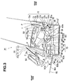
- the image-reading unit 90 (the "image-reading unit” described hereinafter is intended to involve a frame member constituting an entire body thereof) is mounted onto the front surface of the exterior cover 2 of the body 1 and so constructed as to be rotatable around a shaft 2b in the direction of an arrow E.
- the image-reading unit 90 is detachably mounted to the exterior cover 2 by engaging claws 90a provided on a lower portion thereof with claw-receiving portions 2c formed in the exterior cover 2.
- the image-reading unit 90 comprises, sequentially from the top in the vertical direction, a document-feeding tray 91 on which an original document Q is set, a feed roller 92 for supplying the original document Q and a contact image sensor 93 for reading an image information from the original document Q. These components are arranged in approximately linear manner.
- the document-feeding tray 91 is constructed in a retractable manner so as to be accommodated within the image-reading unit 90 when not used.
- a separation pad 94 is disposed on an inclined lower side of the feed roller 92, and a reading roller 95 is disposed below the contact image sensor 93 in opposite relation to each other.
- the contact image sensor 93 is urged toward the reading roller 95 by means of a spring 96 so as to be brought into pressure contact with the reading roller 95.
- a conveying guide 97 is arranged between the feed roller 92 and the contact image sensor 93.
- the feed roller 92 and the reading roller 95 are driven by a drive mechanism mounted in the image-reading unit 90 and including a motor (not shown) as a driving source.
- the picture signal read out by the contact image sensor 93 is processed in a board 98 mounted within the image-reading unit 90, and sent to the body 1 through a connector (not shown) coupled with the body 1.
- the connector is of a floating type and adapted to conduct ON/OFF control of the electrical connection between the image-reading unit 90 and the body 1 in response to attaching or detaching operations of the image-reading unit 90.
- the original document Q is set (in face-up manner) on the document-feeding tray 91 such that a surface of the original document Q on which an image information to be read is present, faces upwardly.
- the feed roller 92 begins to rotate and feeds the original document Q to the downstream side thereof by the cooperation with the separation pad 94 while preventing two or more documents from being fed simultaneously.
- the fed original document Q is then guided through the conveying guide 97 to a nip portion between the contact image sensor 93 and the reading roller 95.
- the image-bearing surface of the thus-guided original document Q is pressed against the contact image sensor 93 by the reading roller 95 while being conveyed therethrough.
- the original document Q is then conveyed through an delivery port 90b, and delivered onto the face-up delivery tray 82 with the image-bearing surface thereof facing upward.
- the picture signal read out by the contact image sensor 93 is sent to the body 1 through the board 98 to output a printed image.
- the picture signal is sent to a computer through the body 1 to conduct image-processing, and thereafter the processed image is fed back to the body 1 for printing.
- the user can perform, from the front side of the body 1, all the operations including the setting of the recording paper P on the document-feeding tray 13, the setting of the original document Q on the document-feeding tray 91 of the image-reading unit 90, the removal of the recording paper P delivered onto the delivery tray 22 and the removal of the recording paper P and the original document Q delivered onto the face-up delivery tray 82.
- the removal of the process cartridge 40 can be readily performed from the front side of the body 1 by opening the exterior cover 2 provided on the front side of the body 1 without necessity of removing the image-reading unit 90.
- the attachment or detachment of the image-reading unit 90 relative to the body 1 can be readily performed from the front side of the body 1.
- the document-feeding tray 91 on which the original document Q is set is constructed so as to be retractable into the image-reading unit 90.
- the front half portion of the original document Q is supported on a part 90c of the image-reading unit 90, while the rear half portion of the original document Q is supported on the delivery tray 22 or the extension tray 23.
- the document-feeding tray 91 is not required to be pulled out of the image-reading unit, so that further improvement in operability can be achieved.
- the document-feeding tray 91 for the original document Q can be omitted, no tray is required for feeding and delivering the original document Q, thereby achieving compact size of the image-reading unit 90 itself, reduction in weight and decrease in production cost.
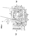
- the image-reading unit 90 comprises, sequentially from the top in the vertical direction, a portion 90c of the image-reading unit 90 on which the original document Q is set, a feed roller 92 for supplying the original document Q and the contact image sensor 93 as an image-reading means. These components are also arranged in approximately linear manner, similarly to those of the second embodiment.
- the separation pad 94 is disposed on an inclined upper side of the feed roller 92, and the reading roller 95 is disposed above the contact image sensor 93 in an opposite relation to each other.
- the contact image sensor 93 is urged toward the reading roller 95 by means of the spring 96 so as to be brought into pressure contact therewith.
- the conveying guide 97 is disposed between the feed roller 92 and the contact image sensor 93.
- the original document Q is set (face-down) on the portion 90c of the image-reading unit 90 with a surface thereof on which an image to be read is present facing downward.
- the feed roller 92 begins to rotate and supplies the original document Q to the downstream side thereof by the cooperation with the separation pad 94 while preventing two or more original documents Q from being fed simultaneously.
- the fed original document Q is guided through the conveying guide 97 to the nip portion between the contact image sensor 93 and the reading roller 95.
- the image-bearing surface of the original document Q is pressed against the contact image sensor 93 by the reading roller.
- the original document Q is then delivered through the delivery port 90b onto the face-up delivery tray 82 with the image-bearing surface facing downward.
- the recording paper P is delivered on the face-up delivery tray 82 with the image-printed surface thereof facing upward, while the original document Q is delivered on the same face-up delivery tray 82 with the image-bearing surface thereof facing downward.
- the user does not confuse the recording paper P with the original document Q, and therefore can clearly distinguish them from each other.
- the image-reading unit 90 comprises, sequentially from the bottom in the vertical direction, the portion 90c of the image-reading unit 90 on which the original document Q is set, the feed roller 92 for supplying the original document Q and the contact image sensor 93 as an image-reading means. These components are arranged in approximately linear manner.
- the separation pad 94 is disposed on an inclined lower side of the feed roller 92, and the reading roller 95 is disposed below the contact image sensor 93 in an opposite relation to each other.
- the contact image sensor 93 is urged toward the reading roller 95 by means of the spring 96 so as to be brought into pressure contact therewith.
- the conveying guide 97 is disposed between the feed roller 92 and the contact image sensor 93. That is, in the thus-arranged image-reading unit 90, when the original document Q is set (face-up setting) on the portion 90c of the image-reading unit 90 with a surface thereof on which an image to be read is present facing upward, the feed roller 92 begins to rotate in response to the signal indicative of initiation of image-reading which is input to the board 98, and supplies the original document Q in the upward direction by the cooperation with the separation pad 94 while preventing two or more original documents Q from being fed simultaneously. The fed original document Q is guided through the conveying guide 97 to the nip portion between the contact image sensor 93 and the reading roller 95.
- the original document Q is further guided while the image-bearing surface thereof is pressed against the contact image sensor 93 by the reading roller, and delivered through a delivery port 90b onto the delivery tray 22 or the extension tray 23 with the image-bearing surface in face-up (F/U) status.
- the document-feeding tray for supplying the original document Q can be omitted from the arrangement described in the afore-mentioned first embodiment which exhibits similar operability.
- the arrangement of this embodiment can satisfy requirements of compact size, reduced weight and low production cost of the image-reading unit 90 simultaneously.
- the recording paper P is delivered onto the delivery tray 22 with the image-printed surface thereof facing downward
- the original document Q is delivered onto the same delivery tray 22 with the image-bearing surface thereof facing upward. Accordingly, the user does not confuse the recording paper P with the original document Q, and therefore can clearly distinguish them from each other.
- the image-reading unit 90 is formed with a lower horizontal surface 90d, and therefore can be self-standing on a horizontal plane by itself. Accordingly, when the image-reading unit 90 which is removed from the body 1 is placed on such a horizontal plane and coupled to the body 1 through a connector (not shown), it can be used independently.
- the image-reading unit 90 can be used in either state as attached to the body 1 or as removed from the body 1 for independent use according to the user's demand, there can be provided the multi-functional image-forming apparatus which can be readily operated by many users irrespective of service places and applications therefor.
- an document-reading unit is mounted to an exterior cover (cover) through which at least part of the image-forming means can be removed from the interior of the apparatus, the exterior cover can be operated without being disturbed by the document-reading unit, thereby smoothly performing the attaching and detaching operations of at least part of the image-forming means.
- a common delivery tray can be used for both the recording paper and the original document, which leads to achievement of space-saving therein and therefore enables the image-forming apparatus to be minimized. Further, since the recording paper and the original document is delivered to the tray with the image-printed or image-bearing surfaces thereof facing in different directions, the user can be prevented from confusing the recording paper with the original document.
- the present invention relates to an image-forming apparatus which is small in size and excellent in operability.
- an image-forming apparatus comprises: a main assembly; an image-forming means for forming an image on a recording medium, at least a part of said image-forming means being removably attached to an interior of said main assembly; a cover for opening and closing said interior of the main assembly, wherein at least said a part of the image-forming means is removable from the interior of the main assembly when said cover is opened; and a document-reading unit for reading an original document, said document-reading means being mounted to said cover so as to be moved together with the cover.
Abstract
Description
Claims (10)
- An image-forming apparatus, comprising:a main assembly;an image-forming means for forming an image on a recording medium, at least a part of said image-forming means being removably attached to an interior of said main assembly;a cover for opening and closing said interior of the main assembly, wherein at least said a part of the image-forming means is removable from the interior of the main assembly when said cover is opened; anda document-reading unit for reading an original document, said document-reading means being mounted to said cover so as to be moved together with the cover.
- An image-forming apparatus as claimed in claim 1, wherein said document-reading unit is removably mounted to said cover.
- An image-forming apparatus as claimed in claim 1, further comprising a delivery tray for receiving said recording medium on which the image has been formed by said image-forming means, said delivery tray being formed integrally with said cover.
- An image-forming apparatus as claimed in claim 1, wherein said document-reading unit is mounted to a front surface of said image-forming apparatus.
- An image-forming apparatus as claimed in claim 3, wherein said document-reading unit is mounted on a front side of said delivery tray.
- An image-forming apparatus as claimed in claim 1, further comprisinga first sheet-feeding tray for receiving said recording medium to be supplied to said image-forming means;a delivery tray for receiving said recording medium on which the image has been formed by said image-forming means; anda second sheet-feeding tray for receiving said original document to be supplied to said document-reading unit,said recording medium and said original document being supported in said first and second sheet-feeding trays and said delivery tray in approximately upright state relative to a bottom surface of said image-forming apparatus.
- An image-forming apparatus as claimed in claim 1, wherein said at least a part of said image-forming means is at least one element selected from an electrophotographic photosensitive member,a charging means for electrifying said electrophotographic photosensitive member, a developing means for supplying a developing material to said electrophotographic photosensitive member and a cleaning means for cleaning said electrophotographic photosensitive member.
- An image-forming apparatus having a function for reading an original document, comprising:an image-forming means for forming the image on a recording medium;a document-reading means for reading the original document; anda common tray for receiving said recording medium on which the image has been formed by said image-forming means, and said original document from which the image has been read out by said document-reading means,said recording medium and said original document being received in said common tray in a manner that front and rear surfaces thereof facing in different directions from each other.
- An image-forming apparatus as claimed in claim 8, further comprising a cover for opening and closing an interior of said image-forming apparatus in such a manner that when said cover is opened, at least a part of said image-forming means is removable from said interior of the image-forming apparatus, said document-reading means being mounted onto said cover so as to be moved together with the cover.
- An image-forming apparatus as claimed in claim 9, wherein said common tray is formed integrally with a part of said cover.
Applications Claiming Priority (2)
| Application Number | Priority Date | Filing Date | Title |
|---|---|---|---|
| JP8169326A JPH1020595A (en) | 1996-06-28 | 1996-06-28 | Electrophotographic image forming device |
| JP169326/96 | 1996-06-28 |
Publications (3)
| Publication Number | Publication Date |
|---|---|
| EP0817459A2 true EP0817459A2 (en) | 1998-01-07 |
| EP0817459A3 EP0817459A3 (en) | 1998-11-11 |
| EP0817459B1 EP0817459B1 (en) | 2006-08-09 |
Family
ID=15884481
Family Applications (1)
| Application Number | Title | Priority Date | Filing Date |
|---|---|---|---|
| EP97110560A Expired - Lifetime EP0817459B1 (en) | 1996-06-28 | 1997-06-27 | Electrophotographic image-forming apparatus with detachably mounted document-reading unit |
Country Status (5)
| Country | Link |
|---|---|
| US (1) | US5884117A (en) |
| EP (1) | EP0817459B1 (en) |
| JP (1) | JPH1020595A (en) |
| DE (1) | DE69736452T2 (en) |
| HK (1) | HK1005285A1 (en) |
Cited By (3)
| Publication number | Priority date | Publication date | Assignee | Title |
|---|---|---|---|---|
| EP1079594A2 (en) * | 1999-08-24 | 2001-02-28 | Canon Kabushiki Kaisha | Image reading apparatus and image processing apparatus |
| EP1221808A2 (en) | 2000-12-25 | 2002-07-10 | Canon Kabushiki Kaisha | Image forming apparatus |
| EP2262218A3 (en) * | 2004-09-21 | 2013-03-13 | Brother Kogyo Kabushiki Kaisha | Image processing apparatus |
Families Citing this family (22)
| Publication number | Priority date | Publication date | Assignee | Title |
|---|---|---|---|---|
| US7379218B1 (en) | 1996-11-05 | 2008-05-27 | Fujitsu Limited | Apparatus equipped with removable scanner unit |
| JPH10134163A (en) * | 1996-11-05 | 1998-05-22 | Pfu Ltd | Device with scanner |
| JP3478736B2 (en) * | 1997-09-16 | 2003-12-15 | キヤノン株式会社 | Image forming device |
| US6078765A (en) * | 1997-10-28 | 2000-06-20 | Canon Kabushiki Kaisha | Image forming apparatus |
| JPH11146100A (en) * | 1997-11-06 | 1999-05-28 | Canon Inc | Image reading and recording device |
| JP3364585B2 (en) * | 1997-12-22 | 2003-01-08 | シャープ株式会社 | Image forming device |
| US6961152B1 (en) * | 1998-01-08 | 2005-11-01 | Brother Kogyo Kabushiki Kaisha | Multi-functional device having vertically arranged scanner and printer sections |
| JPH11341217A (en) * | 1998-05-22 | 1999-12-10 | Canon Inc | Image processor |
| US6144813A (en) * | 1998-07-06 | 2000-11-07 | Canon Kabushiki Kaisha | Image forming apparatus provided with conveying path changeover device |
| US6011940A (en) * | 1998-09-25 | 2000-01-04 | Hewlett-Packard Co. | Method and apparatus for convenience copy collation during a current print job |
| US6131902A (en) * | 1998-11-20 | 2000-10-17 | Ricoh Company, Ltd. | Sheet feeding paths for apparatus with feed paths selectable to correspond to desired function of apparatus |
| US6208828B1 (en) * | 1998-12-15 | 2001-03-27 | Canon Kabushiki Kaisha | Compact image forming apparatus |
| JP4557448B2 (en) * | 2001-02-28 | 2010-10-06 | キヤノン株式会社 | Image forming apparatus |
| US7382506B2 (en) * | 2002-12-24 | 2008-06-03 | Canon Kabushiki Kaisha | Image reading and recording apparatus |
| JP2004302004A (en) | 2003-03-31 | 2004-10-28 | Brother Ind Ltd | Image forming apparatus and process cartridge |
| US7567365B2 (en) * | 2003-05-30 | 2009-07-28 | Kyocera Mita Corporation | Image reading apparatus |
| JP2005077478A (en) | 2003-08-28 | 2005-03-24 | Canon Inc | Image forming apparatus |
| US8098411B2 (en) * | 2004-08-31 | 2012-01-17 | Brother Kogyo Kabushiki Kaisha | Image reading apparatus |
| US7636528B2 (en) | 2005-03-30 | 2009-12-22 | Brother Kogyo Kabushiki Kaisha | Image-forming device including image-forming section, paper supply unit, and discharge unit and ornamental member therefor |
| JP4669358B2 (en) * | 2005-09-13 | 2011-04-13 | キヤノン株式会社 | Image forming apparatus |
| JP4928839B2 (en) | 2006-06-12 | 2012-05-09 | 株式会社リコー | Image forming apparatus |
| US7931273B2 (en) * | 2007-05-24 | 2011-04-26 | Canon Kabushiki Kaisha | Sheet stacking apparatus and image forming apparatus |
Citations (3)
| Publication number | Priority date | Publication date | Assignee | Title |
|---|---|---|---|---|
| US5028957A (en) * | 1988-12-01 | 1991-07-02 | Minolta Camera Kabushiki Kaisha | Image forming apparatus with an image reading function |
| DE4217831A1 (en) * | 1991-05-31 | 1992-12-03 | Asahi Optical Co Ltd | Safety stopping device for image prodn. unit with main housing - has swivel element adjustable between open position lifted from main housing and closed position lying on main housing |
| US5559609A (en) * | 1993-07-30 | 1996-09-24 | Matsushita Graphic Communication Systems, Inc. | Facsimile transceiver |
Family Cites Families (4)
| Publication number | Priority date | Publication date | Assignee | Title |
|---|---|---|---|---|
| JP2766679B2 (en) * | 1989-08-04 | 1998-06-18 | キヤノン株式会社 | Document transport reading device |
| JPH05145706A (en) * | 1991-03-05 | 1993-06-11 | Canon Inc | Image reading device |
| JPH0523666U (en) * | 1991-09-05 | 1993-03-26 | 旭光学工業株式会社 | Reading head and original urging release structure in the original reading device |
| US5579129A (en) * | 1993-12-17 | 1996-11-26 | Canon Kabushiki Kaisha | Original reading apparatus and information processing apparatus with original reading apparatus |
-
1996
- 1996-06-28 JP JP8169326A patent/JPH1020595A/en active Pending
-
1997
- 1997-06-27 US US08/884,620 patent/US5884117A/en not_active Expired - Fee Related
- 1997-06-27 DE DE69736452T patent/DE69736452T2/en not_active Expired - Lifetime
- 1997-06-27 EP EP97110560A patent/EP0817459B1/en not_active Expired - Lifetime
-
1998
- 1998-05-22 HK HK98104454A patent/HK1005285A1/en not_active IP Right Cessation
Patent Citations (3)
| Publication number | Priority date | Publication date | Assignee | Title |
|---|---|---|---|---|
| US5028957A (en) * | 1988-12-01 | 1991-07-02 | Minolta Camera Kabushiki Kaisha | Image forming apparatus with an image reading function |
| DE4217831A1 (en) * | 1991-05-31 | 1992-12-03 | Asahi Optical Co Ltd | Safety stopping device for image prodn. unit with main housing - has swivel element adjustable between open position lifted from main housing and closed position lying on main housing |
| US5559609A (en) * | 1993-07-30 | 1996-09-24 | Matsushita Graphic Communication Systems, Inc. | Facsimile transceiver |
Cited By (6)
| Publication number | Priority date | Publication date | Assignee | Title |
|---|---|---|---|---|
| EP1079594A2 (en) * | 1999-08-24 | 2001-02-28 | Canon Kabushiki Kaisha | Image reading apparatus and image processing apparatus |
| EP1079594A3 (en) * | 1999-08-24 | 2002-09-11 | Canon Kabushiki Kaisha | Image reading apparatus and image processing apparatus |
| US6714326B1 (en) | 1999-08-24 | 2004-03-30 | Canon Kabushiki Kaisha | Image reading apparatus and image processing apparatus |
| EP1221808A2 (en) | 2000-12-25 | 2002-07-10 | Canon Kabushiki Kaisha | Image forming apparatus |
| EP1221808A3 (en) * | 2000-12-25 | 2004-08-25 | Canon Kabushiki Kaisha | Image forming apparatus |
| EP2262218A3 (en) * | 2004-09-21 | 2013-03-13 | Brother Kogyo Kabushiki Kaisha | Image processing apparatus |
Also Published As
| Publication number | Publication date |
|---|---|
| DE69736452T2 (en) | 2007-08-23 |
| JPH1020595A (en) | 1998-01-23 |
| EP0817459A3 (en) | 1998-11-11 |
| DE69736452D1 (en) | 2006-09-21 |
| US5884117A (en) | 1999-03-16 |
| HK1005285A1 (en) | 1998-12-31 |
| EP0817459B1 (en) | 2006-08-09 |
Similar Documents
| Publication | Publication Date | Title |
|---|---|---|
| US5884117A (en) | Image-forming apparatus with a cover-mounted document-reading unit and a common tray for receiving a recording medium and original document features | |
| US5839032A (en) | Image forming apparatus having selectably controlled sheet discharge paths | |
| JP2851303B2 (en) | Printer device | |
| US8736921B2 (en) | Rotatable scanner and image forming apparatus | |
| JP3877367B2 (en) | Image forming apparatus | |
| JP3639614B2 (en) | Multifunctional image forming device | |
| US6473576B1 (en) | Image forming apparatus with sheet feeding device having sheet supporting portion | |
| JP3356172B2 (en) | Image forming device | |
| JP2004212494A (en) | Image forming apparatus | |
| JP2006030418A (en) | Image forming apparatus | |
| JP3465701B2 (en) | Copier | |
| JP3433740B2 (en) | Image forming device | |
| JP2005015203A (en) | Image formation apparatus | |
| JPH11255403A (en) | Image formation device | |
| JPH0367272A (en) | Color image forming device | |
| JP2006293407A (en) | Image forming apparatus | |
| JPH11255405A (en) | Image formation device | |
| JP3647016B2 (en) | Image forming apparatus | |
| JP3854596B2 (en) | Image forming apparatus | |
| JP2002139876A (en) | Image forming device | |
| JPH08286450A (en) | Combined machine for image reader or the like | |
| JPH11255399A (en) | Image forming device | |
| JPH05333616A (en) | Electrophotographic device | |
| JP3806066B2 (en) | Image forming apparatus | |
| JPH09311514A (en) | Image reading composite device |
Legal Events
| Date | Code | Title | Description |
|---|---|---|---|
| PUAI | Public reference made under article 153(3) epc to a published international application that has entered the european phase |
Free format text: ORIGINAL CODE: 0009012 |
|
| AK | Designated contracting states |
Kind code of ref document: A2 Designated state(s): DE FR GB IT |
|
| PUAL | Search report despatched |
Free format text: ORIGINAL CODE: 0009013 |
|
| AK | Designated contracting states |
Kind code of ref document: A3 Designated state(s): AT BE CH DE DK ES FI FR GB GR IE IT LI LU MC NL PT SE |
|
| 17P | Request for examination filed |
Effective date: 19990329 |
|
| AKX | Designation fees paid |
Free format text: DE FR GB IT |
|
| 17Q | First examination report despatched |
Effective date: 20040507 |
|
| GRAP | Despatch of communication of intention to grant a patent |
Free format text: ORIGINAL CODE: EPIDOSNIGR1 |
|
| RTI1 | Title (correction) |
Free format text: ELECTROPHOTOGRAPHIC IMAGE-FORMING APPARATUS WITH DETACHABLY MOUNTED DOCUMENT-READING UNIT |
|
| GRAS | Grant fee paid |
Free format text: ORIGINAL CODE: EPIDOSNIGR3 |
|
| GRAA | (expected) grant |
Free format text: ORIGINAL CODE: 0009210 |
|
| AK | Designated contracting states |
Kind code of ref document: B1 Designated state(s): DE FR GB IT |
|
| PG25 | Lapsed in a contracting state [announced via postgrant information from national office to epo] |
Ref country code: IT Free format text: LAPSE BECAUSE OF FAILURE TO SUBMIT A TRANSLATION OF THE DESCRIPTION OR TO PAY THE FEE WITHIN THE PRESCRIBED TIME-LIMIT;WARNING: LAPSES OF ITALIAN PATENTS WITH EFFECTIVE DATE BEFORE 2007 MAY HAVE OCCURRED AT ANY TIME BEFORE 2007. THE CORRECT EFFECTIVE DATE MAY BE DIFFERENT FROM THE ONE RECORDED. Effective date: 20060809 |
|
| REG | Reference to a national code |
Ref country code: GB Ref legal event code: FG4D |
|
| REF | Corresponds to: |
Ref document number: 69736452 Country of ref document: DE Date of ref document: 20060921 Kind code of ref document: P |
|
| REG | Reference to a national code |
Ref country code: HK Ref legal event code: GR Ref document number: 1005285 Country of ref document: HK |
|
| ET | Fr: translation filed | ||
| PLBE | No opposition filed within time limit |
Free format text: ORIGINAL CODE: 0009261 |
|
| STAA | Information on the status of an ep patent application or granted ep patent |
Free format text: STATUS: NO OPPOSITION FILED WITHIN TIME LIMIT |
|
| 26N | No opposition filed |
Effective date: 20070510 |
|
| PGFP | Annual fee paid to national office [announced via postgrant information from national office to epo] |
Ref country code: FR Payment date: 20100706 Year of fee payment: 14 |
|
| PGFP | Annual fee paid to national office [announced via postgrant information from national office to epo] |
Ref country code: IT Payment date: 20100617 Year of fee payment: 14 |
|
| PGFP | Annual fee paid to national office [announced via postgrant information from national office to epo] |
Ref country code: GB Payment date: 20100401 Year of fee payment: 14 Ref country code: DE Payment date: 20100630 Year of fee payment: 14 |
|
| GBPC | Gb: european patent ceased through non-payment of renewal fee |
Effective date: 20110627 |
|
| PG25 | Lapsed in a contracting state [announced via postgrant information from national office to epo] |
Ref country code: IT Free format text: LAPSE BECAUSE OF NON-PAYMENT OF DUE FEES Effective date: 20110627 |
|
| REG | Reference to a national code |
Ref country code: FR Ref legal event code: ST Effective date: 20120229 |
|
| REG | Reference to a national code |
Ref country code: DE Ref legal event code: R119 Ref document number: 69736452 Country of ref document: DE Effective date: 20120103 |
|
| PG25 | Lapsed in a contracting state [announced via postgrant information from national office to epo] |
Ref country code: FR Free format text: LAPSE BECAUSE OF NON-PAYMENT OF DUE FEES Effective date: 20110630 Ref country code: DE Free format text: LAPSE BECAUSE OF NON-PAYMENT OF DUE FEES Effective date: 20120103 |
|
| PG25 | Lapsed in a contracting state [announced via postgrant information from national office to epo] |
Ref country code: GB Free format text: LAPSE BECAUSE OF NON-PAYMENT OF DUE FEES Effective date: 20110627 |