EP0817122A2 - Filter and raster operations - Google Patents
Filter and raster operations Download PDFInfo
- Publication number
- EP0817122A2 EP0817122A2 EP97301078A EP97301078A EP0817122A2 EP 0817122 A2 EP0817122 A2 EP 0817122A2 EP 97301078 A EP97301078 A EP 97301078A EP 97301078 A EP97301078 A EP 97301078A EP 0817122 A2 EP0817122 A2 EP 0817122A2
- Authority
- EP
- European Patent Office
- Prior art keywords
- filter
- raster
- destination
- pattern
- input
- Prior art date
- Legal status (The legal status is an assumption and is not a legal conclusion. Google has not performed a legal analysis and makes no representation as to the accuracy of the status listed.)
- Granted
Links
Images


Classifications
-
- G—PHYSICS
- G06—COMPUTING; CALCULATING OR COUNTING
- G06T—IMAGE DATA PROCESSING OR GENERATION, IN GENERAL
- G06T15/00—3D [Three Dimensional] image rendering
- G06T15/005—General purpose rendering architectures
-
- G—PHYSICS
- G06—COMPUTING; CALCULATING OR COUNTING
- G06T—IMAGE DATA PROCESSING OR GENERATION, IN GENERAL
- G06T15/00—3D [Three Dimensional] image rendering
- G06T15/50—Lighting effects
- G06T15/503—Blending, e.g. for anti-aliasing
Definitions
- the invention is in the field of display technology and deals specifically with processing color and gray scale data which is to be sent to a color or gray scale monitor or to a color laser printer or other continuous raster scan device using a novel mechanism for handling complex graphics operatives.
- the invention is part of the continuing evolution of software and hardware graphics and memory reduction technology to enable the printing and display of complex graphics images using less memory than would be the case without using the invented techniques.
- the invention specifically addresses complex logic applied to continuous-tone data using new operatives called filter operations.
- a novel approach to handling transparency operatives simultaneously with raster operatives in a graphics environment is disclosed. This is achieved by introducing filter operations to obtain the effect of transparency. Filter operations work cooperatively with grayscale and continuous-tone color raster operations. The introduction of filter operations, and their cooperation with raster operations allows this otherwise computationally complex problem to be served by a single hardware circuit. The efficiency of this approach lends itself well to real-time applications such as monochrome and color laser printing. The solution is also applicable to displaying complex graphics on a video display device.
- Figure 1 is a block diagram of a system showing the environment in which the present invention may be used.
- Figure 2 is a representation of pixels forming a rectangular grid.
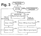
- Figure 3 is a flowchart showing the cooperative evaluation algorithm.
- Figure 4 is a block diagram of a circuit for implementing the cooperative evaluation algorithm described in Figure 3 for three operands.
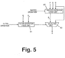
- Figure 5 is a block diagram of a circuit for implementing the preferred embodiment of the cooperative evaluation algorithm for two operands.
- FIG 1 is a block diagram of a system showing the environment in which the present invention may be used.
- U.S. Patent No. 5,204,804 a method and apparatus for generating graphics information for display on a continuous synchronous raster output device is disclosed.
- the system is shown in Figure 4 of U.S. Patent No. 5,204,804 and is for printing on monochrome output devices.
- the present invention is directed to improvements in the system described in U.S. Patent No. 5,204,804 to handle color images as well as monochrome images.
- the basic graphics orders described in U.S. Patent No. 5,204,804 are enhanced to support color and additional orders are defined for filters and other operations as described below.
- the enhancements to the basic orders described in U.S. Patent No. 5,204,804 and additional orders defined for filters and other operations needed for operation of the present invention provide transparency information to realtime blit processor 37, also referred to as the graphics execution unit (GEU) in U.S. Patent No. 5,204,804.
- This includes the following information (1) a two operand filter function F(P F , S F ) or, optionally, a three-operand filter function F(P F , S F, D F ); (2) the source filter bitmap, S F , (3) a pattern filter bitmap, P F ; and (4) a destination bitmap D F , if the three-operand filter function is used.
- the term "halftone" is used instead of "pattern” and halftone mask is used instead of pattern filter bitmap.
- the additional orders defined for filters and other operations needed for operation of the invention perform the following functions: Set Filter Boolean Sets a hardware "register" with a boolean value that will be used in the next and subsequent operations until another Set Filter Boolean command replaces it.
- Set Source Filter Address Sets the starting address of the source filter to be used until another Set Source Filter command replaces it.
- Set Pattern Filter Address Sets the starting address of the pattern filter to be used until another Set Pattern Filter command replaces it.
- Raster graphics data is a rectangular grid where each grid element is a called a pixel.
- An example is shown in Figure 1.
- the size of the grid is described in terms of width and height.
- a pixel can be uniquely identified by its ⁇ x, y ⁇ coordinate, where 1 ⁇ x ⁇ width and 1 ⁇ y ⁇ height, within the rectangular grid. If G is a rectangular grid, a pixel is denoted within G as G ⁇ x, y ⁇ .
- a pixel can be broken down into components and depth.
- a pixel component represents the contribution of a primary color to the pixel.
- each pixel In a monochrome printer or black and white video display, each pixel has only one component, and that component represents the amount of black ink (printer) or white light (display) .
- a pixel In a color environment, a pixel normally has three or four components.
- a color video display typically has three components: red; green; and blue. Pixels with these color components are called RGB pixels.
- a printer usually has three or four components: cyan; magenta; yellow; and, optionally, black. Pixels with these components are called CMY pixels or CMYK pixels.
- new models such as hi-fi color, are emerging.
- other models to represent color which are not visual such as the many variations of CIE-XYZ device independent color spaces, exist. The present invention has application to all of these models.
- the depth of a pixel determines the number of discernible values each pixel component may have. Typically depth is 1, 2, 4, or 8. Given a value d for a pixel's depth, each component has 2 d discernible values. For example, a pixel with depth 8 allows each component to have 256 discernible values. These can be numbered sequentially from 0 to 2 d -1.
- each pixel component is represented as a binary value requiring d bits, where a bit is either a 1 " or a 0 " .
- a pixel component with value 201 and depth 8 is represented using the binary value 11001001 " .
- a logical operation is a mapping of truth values into a truth value.
- a truth value has one of two values: true or false where true is denoted as 1 " and false is denoted as 0 " .
- a compound logical operation is an arbitrary combination of logical operations. For example, if P, Q, and R are truth values, then (( ⁇ P) & Q)
- a pixel operation is a compound logical operation R applied to corresponding bits of one or more equally sized pixels. For example, given two pixels p1 and p2 with values 1100 “ , and 1010 " , respectively, then ⁇ p1 becomes 0011 " , p1 & p2 becomes 1000 " , and p1
- a raster operation is any pixel operation R applied to each set of corresponding pixels of one or more equally sized raster graphics data operands.
- a raster operation is called a ROP in a Microsoft Windows environment, a Logical Operation in the various dialects of Hewlett Packard's PCL5 language, and a Boolean operation in an Intel i961KD processor or a Motorola 68322 processor.
- the number of operands is usually three, pattern (P), source (S), and destination (D) , and the result off the raster operation replaces D.
- P is typically smaller than S and S is smaller than D.
- Sequences of raster operations are used in graphics environments to construct complex images.
- a page of a business document may contain a lot of text and a figure or two. Or a presentation may have a shaded background, borders, clipart and text.
- These types of page images are constructed by their applications using a sequence of raster operations. For example, first a background may be painted. This may be followed by several lines of text. Then some pieces of clipart may be inserted. Each of these steps may use a different raster operation to achieve a specific effect.
- the destination is the holder off the image being constructed, and typically represents a page or a video display.
- a source is a graphical object that needs to be placed on the destination. For example, a character, a line, a polygon, or a photograph are typical examples of a source.
- a pattern is an erect to apply to the source. For example, one may construct a checkerboard by applying a pattern with alternating colored boxes to a rectangular source.
- Raster operations are simplified for the case where depth is 1. This is called bi-level monochrome and represents the traditional monochrome laser printer.
- a gray letter such as an "O" onto a page.
- An “O” is represented digitally with “1”s denoting the ring and "0"s (zeros) denoting the interior.
- the desired gray would be represented as the pattern.
- the pattern would contain a combination of "1"s and "0"s in a ratio that produces a desired shade of gray.
- bitmap describes raster graphics data for the specific case in which the depth is 1 and there is 1 component, whereas raster graphics data is the general term for any depth or number of components.
- a gray value on a monochrome device with a depth of 1 is represented as a pattern.
- a pattern is a bitmap in which the percentage of 1 " s represents a shade of gray.
- Table 2 shows all possible combinations of three operands and eight data values and can be used to achieve this goal.
- the gray character example will be used to demonstrate.
- a compound logical operation is constructed for each 1 " in this result, and these operations are combined by use of the
- 11100010 can be expressed as (P & S & D)
- a given raster operation may affect a destination area that has had one or more objects already placed in it. Therefore, a new source object may intersect objects already in the destination. In one case, one may wish for the source to cover the destination object along the intersection points. In another case and as in the example above, one may wish those parts of the source that have color to cover the destination, but those parts of the source that are colorless to not affect the destination. Or, one may wish that only those parts of the source not intersecting existing destination objects get placed on the destination. Many other possibilities exist.
- transparency This is a secondary attribute applied to the raster operation that further determines the portions of the pattern and source that get applied to the destination. It describes how to apply the colorless pixels in the operands. As an opposite of transparency, the word opaque is often used.
- transparency is an attribute associated with source and pattern objects. This makes it difficult to achieve the effect of giving existing destination objects precedence.
- This definition may be generalized to include transparency as an attribute of destination thereby removing this limitation. This makes possible an operation in which one wishes the existing destination objects to not get covered, so that only those parts of the source that do not intersect existing destination objects are placed on the destination.
- the transparency model assigns a truth value to each pixel which denotes colored “ or colorless " using 1 " and 0 " , respectively, for these truth values. Since transparency is a relation upon truth values, logical operations may be applied.
- Source transparency determines the effect of colorless pixels in the source as they are applied to the destination.
- a colorless value is allowed to be the same value as white in a CMY or CMYK model, or black in an RGB model.
- pattern transparency determines the effect of colorless pixels in the pattern, but only as applied through the colored pixels of the source. Only the colored pixels in the source are affected by pattern pixels. The affected source pixels become transparent depending upon the pattern transparency. A colorless pixel in a transparent pattern causes a corresponding colored pixel in the source to become transparent, thereby not affecting the destination.
- Colorless source pixels are not affected by pattern transparency, they are only subject to source transparency.
- the destination may already consist of a light gray and the desired effect is to place a dark gray character on top of the light gray background such that the background is visible through the colorless pixels of the character (i.e., the inside of an O " ). This is the purpose of transparency.
- the effect achieved in the previous example can also be realized using a transparency mode of TO " and a raster operation D ⁇ S & P ".
- the transparency mode states that only those pixels in S that are not colorless affect D. Therefore, in the case of the character O " , the interior of the character is colorless so that the corresponding destination pixels are preserved. Only the outline portion of the character affects the destination, and this would be done according to the pattern desired.
- Pixel data of this category is referred to as multiple-bit. This complexity is because pixels may no longer be represented as truth values as there is more than one value that represents color. Consequently, the raster graphics data operands P, S, and D can no longer be used to represent transparency themselves. This is in contrast to the monochrome example in which a pixel is either 1 " or 0 " .
- the multiple-bit pixel problem is uniquely solved by separating the notion of transparency from the notion of raster operation and developing a mutually cooperative model for each. This is different than prior art solutions which use complex algorithms to merge these concepts together. See, for example, PCL 5 Color Technical Reference Manual, " Hewlett Packard, Edition 1, September 1994, Part Number 5961-0635, page 5-12. Specifically, the prior art approaches specify an algorithm that is unique for each transparency mode. This adds complications if one wishes to introduce additional transparency modes.
- the model using the present invention has one algorithm that is suitable for all transparency modes, as well as a complete generalization of transparency beyond the four modes OO, OT, TO, and TT.
- CMY pixels so that white or colorless is defined as all three components having value zero. Each component has a depth of 4.
- the source has three pixels, 100% cyan, 100% magenta, and white (or colorless). 100% implies the maximum amount of color, which at a depth of 4 is 15. In binary form, 15 is written as 1111 ".
- the transparency mode is TO, only S is used to determine transparent pixels. Within S, only the third pixel is colorless. So, the correct result should apply the raster operation to the first two pixels of D and preserve D in the third pixel.
- the raster operation, D ⁇ S & P " applied to the first pixel yields ⁇ 1111,0000,0000 ⁇ and to the second pixel yields ⁇ 0000,0000,0000 ⁇ .
- the third pixel should be preserved so the value of D for this should remain ⁇ 0000,0000,1111 ⁇ .
- Table 4 shows how the correct result is obtained.
- the first two pixels are colored in S so the raster operation is applied to S and P to derive D. Since the third pixel of S is colorless, the pixel in D is preserved.
- the detection of colored and colorless pixels for S is derived from the same data in which the raster operation is applied.
- the data may go through some transformations before the raster operation is evaluated. These transformations introduce additional complications as transparency and raster operations are expressed upon inputs.
- the transformations may be broadly categorized as
- Adjustment is the application of special effects to the input data. For example adding contrast or brightness. Conversion takes color in one of many input forms and maps this data to the form used by the target device. For example, a photograph will likely have RGB raster graphics data, but a printer will likely have CMY or CMYK inks or toners.
- dithering is a process of reducing depth and/or compensating for undesirable characteristics of the target device (e.g., high pitch banding on a laser printer).
- a typical photograph for example, has a depth of 8, whereas a printer may have depths 1, 2, 4, or 8.
- a dithering process is employed to reduce the depth appropriately via a process called halftoning. Dithering can also be used to reorganize color to compensate for disturbing artifacts today's printers may introduce.
- each of these transformations change the raster graphics data. In doing so, each may introduce color into pixels where color was not originally present, or may make some pixels colorless which were not colorless originally.
- Transparency is expressed upon the inputs, independent of the transformations a given system may apply for reproduction purposes. Consequently, the recognition of colored and colorless pixels must be at the input level.
- a hardware implementation of cooperative filter and raster operations requires an interface that the software can use to set up the transparency filter or filters and the boolean operations to be applied between the filter and the source or pattern.
- the software interface must also include operations or commands (orders) to produce the image in memory.
- the following is a description of the necessary commands followed by an example showing use of the commands that could be used to produce a desired image:
- Opcode Command Description set_bbmap Set Band Buffer Sets the address and other parameters of the image destination. One of these commands is required for each band buffer of an image.
- set_bool_d Raster Operation Boolean Sets a hardware "register” with a boolean value that will be used in the next and subsequent operations until another Set Raster Operation Boolean command replaces it.
- the last portion of the Opcode indicates whether the boolean is to be applied to operations involving the destination (d), the pattern or halftone (hd), source (s), or all three (shd) set_bool_hd set_bool_sd set_bool_shd set_srnask_sa Set Source Filter Address Sets the starting address of the source filter to be used until another Set Source Filter command replaces it.
- set_pmask_sa Set Pattern Filter Address Sets the starting address of the pattern filter to be used until another Set Pattern Filet command replaces it.
- set_htbmap Set Pattern Parameters Establishes the characteristics of the pattern to be used in subsequent raster operations. Characteristics include size, width, and height.
- set_sbmap Set Source Bitmap Parameters Establishes a source bitmap warp to be used in subsequent operations. the warp characteristic applies to all raster operations until it is changed.
- blt2bb_shd Perform Raster Operation with Source, Pattern and Destination Causes the generation of an image based on the current filters and boolean set by previous commands.
- the opcodes set_bbmap, set_bool_d, set_bool_hd, set_bool_sd, set_bool_shd, set_htbmap, set_sbmap and blt2bb_shd are opcodes for commands which are described in U.S. Patent No. 5,204,804.
- the opcodes set_bool_hs, set_smask_sa and set_pmask_sa are opcodes for new operations which would need to be implemented to practice the present invention.
- the details of an implementation of these new opcodes i.e., the operations performed by these opcodes or similar opcodes should be apparent to persons of ordinary skill in art based upon the descriptions contained herein.
- the Perform Raster Operation with Source, Pattern and Destination command includes the arguments necessary to give the memory location of the source, destination, and optional pattern.
- the height and width of the destination are required arguments. Since the memory location of the destination may be expressed as an offset or an x, y location, the command must include an origin for the destination or alternately a "band buffer" designation. Other parameters may be included to allow adjustment of the pattern.
- the source filter boolean is "00001010" in the example shown in Table 4.
- the address of the source filter is "00000110" in the example of Table 4.
- the source filter is assumed to contain one bit for each pixel of the source.
- the boolean to be used in raster operation is "1100000" in the example.
- the pattern filter is assumed to contain one bit for each pixel of the pattern.
- a pattern is applied to an object repeatedly to fill or paint the object. This allows a small pattern to fill a larger object.
- the repeated application of a pattern within the boundaries of an object is often called "tiling.”
- the pattern x remainder and pattern y remainder arguments allow for the adjustment of the origin and tiling of the pattern relative to the source object when they are combined with the destination.
- the x and y remainder arguments are set to the width and height of the pattern.
- the pattern origin or anchor point is the top, left hand corner of the page image. This means that the pattern is applied to the object modulo the pattern width and height.
- the transparency operands P T and S T must be expanded to the depth of the P, S, D such that a colored pixel has a maximum value (2 d -1) and a colorless value is 0.
- the traditional evaluation model has some fundamental problems. First, it is limited to four transparency modes. To add a new transparency mode, therefore, requires a new algorithm for that mode. Certainly in a software only system, this is not a tremendous task. However, in order to add a new algorithm to hardware, one is required to create new hardware. Therefore, this model is not easily extensible to hardware architectures.
- this method excludes destination as a transparency operand. An operation in which one wishes existing destination objects to not get covered, so that only those parts of the source not intersecting existing objects get placed on the destination, becomes very difficult. Allowing destination transparency eliminates this problem.
- the invented solution overcomes all of the problems the traditional solution imposes.
- the basis of this solution is to separate transparency into filter operations and raster operations.
- a model for transparency is defined which includes destination as a transparency operand. This model is based upon filters and filter operations. As the raster operation model is complete, it is not altered. Last, the mechanism which allows the models to work cooperatively is defined.
- a filter is raster graphics data where each pixel has 1 component, has a depth of 1, and whose value represents either colored ( 1 " ) or colorless ( 0 " ).
- Filters denoted P F and S F are used to represent the colored and colorless pixels in the input forms of P and S, respectively. These filters are used to implement the effects of transparency serving the purpose of S T and P T .
- a filter for a source or pattern represents the colored and colorless pixels in the input source or pattern, that is before any transformations.
- Each filter can be constructed by Algorithm 2 shown in Table 6.
- D F A filter is also maintained for D and denoted as D F .
- this filter is constructed from S F and P F much like D is constructed through raster operations applied to P, S, and D.
- D F represents the colored and colorless pixels in D due to a sequence of raster operations with regard to input patterns and sources.
- a filter operation is any compound logical operation F applied on a repetitive basis to corresponding pixels in one or more equally sized filters. Although this definition is generally unbounded, the application in computer graphics processing is described much in the same way as was done with raster operations. For this, three equally sized filters P F , S F , and D F are used.
- F The application of F to its three operands is denoted as F(P F , S F , D F ) .
- a filter operation is used to determine which outputs of a raster operation get applied to the destination. If a filter operation yields a 1 " , the associated output of the raster operation is applied to the corresponding destination pixel. Otherwise, the destination pixel is unchanged. It is in this fashion that the phrase cooperative filter and raster operations " is used.
- the filter be constructed that represents all colorless pixels in S or all colored pixels in S that correspond to colorless pixels in P.
- the combinations 111, 110, 101, 100, 001, and 000 achieve this result.
- This can be written in logic form as (P F & S F & D F )
- Filter operations are used to determine the colored and colorless pixels in the three raster operation operands.
- a raster operation is as defined earlier. In this fashion, a filter operation acts as a sieve with regard to the changes in D. If a filter operation yields a result of a colored pixel, the raster operation is applied to the corresponding destination pixel. Otherwise the destination pixel is unchanged.
- a filter is used to produce the effect of transparency while the raster operation describes the effect of non-transparent operations.
- This mechanism employs the filter operation 65 as an input into the algorithm.
- the difficulty is the creation of the filter and the determination of the filter operation.
- the method has been shown for filter creation explicitly in Algorithm 2. It has also been demonstrated how to construct a filter operation using a logic table. The filter operations suitable for the traditional four transparency modes are shown below:
- D F must be constructed along with D. This is done by applying the raster operation to the three filter operands to produce the destination filter.
- the destination filter is subject to the same transparency effects are the pattern, source, and destination.
- the cooperative filter and raster operation evaluation model is very efficient for software implementation when compared to traditional solutions. Additionally, it has a significant advantage for hardware implementation. This advantage is even greater for devices with real-time constraints such as color and monochrome laser printers. Before discussing these advantages, a circuit for a three operand model is introduced.
- the first raster operation unit computes the result of the raster operation applied to the raster graphics data of the pattern, source, and destination.
- the second raster operation unit computes the result of the raster operation applied to the filters for the pattern, source, and destination.
- the filter operation unit emits 1 " if the result for a pixel is colored according to the filter operation and 0 " otherwise.
- the outputs of the three operation units are input into multiplexors referred to as selection units 81 and 83. Selection is based upon the output of the filter operation logic unit 75. Selection Unit 1 chooses between the result of Raster Operation Logic Unit 1 and operand D. Selection Unit 2 chooses between the result of Raster Operation Logic Unit 2 and operand D F . The outputs of the selection units are the new values for the destination (D') and destination filter (D F '). These outputs of the selection units replace the respective pixels in the destination raster graphics data and the destination filter.
- Table 8 lists the major advantages of the cooperative filter and raster operation model as compared to the traditional model.
- Selection unit 93 is a multiplexor like selection unit 1 or selection unit 2 (elements 81 and 83) in Figure 4.
- This model provides for 16 filter operations.
- To determine the filter operation construct a table of the possible combinations of two operands as shown in Table 9. This table is much like the table for three operands in Table 7.
- Table 9 has four columns which represent the four possible combinations of pixels from two, pattern and source, filters.
- the present invention provides a novel approach to simultaneously handling transparency operatives along with raster operations in a graphics environment. This is achieved by introducing filters and filter operations. These are used to determine the effect of transparency separately from the evaluation of raster operations. This is significantly different than traditional prior art approaches which attempt to combine these two forms of logic into a single operation.
- Algorithm 3 is defined which is a cooperative evaluation model for filters and raster operations. These operations may be computed independently of one another. The cooperation lies in the fact that the results of both are used together to determine the final result. In fact, the result of the filter operation determines what value is output, whereas the raster operation provides one of the values that may be output.
- the invented model generalizes transparency via filter operations to any number of operands, preferably all operands that may affect the destination. This is in contrast to traditional models which only consider a subset of the operands as transparency factors. Further, the invented model is such that one algorithm handles all cases. This is because the transparency or filter operation is a logic operation input to the algorithm. This is significantly different than traditional approaches which customize an algorithm for each transparency mode.
Abstract
Description
| Set Filter Boolean | Sets a hardware "register" with a boolean value that will be used in the next and subsequent operations until another Set Filter Boolean command replaces it. |
| Set Source Filter Address | Sets the starting address of the source filter to be used until another Set Source Filter command replaces it. |
| Set Pattern Filter Address | Sets the starting address of the pattern filter to be used until another Set Pattern Filter command replaces it. |
∼p1 becomes


Specifically, the prior art approaches specify an algorithm that is unique for each transparency mode. This adds complications if one wishes to introduce additional transparency modes. The model using the present invention has one algorithm that is suitable for all transparency modes, as well as a complete generalization of transparency beyond the four modes OO, OT, TO, and TT.


- adjustment,
- conversion, and
- dithering.
| Opcode | Command | Description |
| set_bbmap | Set Band Buffer | Sets the address and other parameters of the image destination. One of these commands is required for each band buffer of an image. |
| set_bool_hs | Set Filter Boolean | Sets a hardware "register" with a boolean value that will be used in the next and subsequent operations until another Set Filter Boolean command replaces it. |
| set_bool_d | Set Raster Operation Boolean | Sets a hardware "register" with a boolean value that will be used in the next and subsequent operations until another Set Raster Operation Boolean command replaces it. The last portion of the Opcode indicates whether the boolean is to be applied to operations involving the destination (d), the pattern or halftone (hd), source (s), or all three (shd) |
| set_bool_hd | ||
| set_bool_sd | ||
| set_bool_shd | ||
| set_srnask_sa | Set Source Filter Address | Sets the starting address of the source filter to be used until another Set Source Filter command replaces it. |
| set_pmask_sa | Set Pattern Filter Address | Sets the starting address of the pattern filter to be used until another Set Pattern Filet command replaces it. |
| set_htbmap | Set Pattern Parameters | Establishes the characteristics of the pattern to be used in subsequent raster operations. |
| Characteristics include size, width, and height. | ||
| set_sbmap | Set Source Bitmap Parameters | Establishes a source bitmap warp to be used in subsequent operations. the warp characteristic applies to all raster operations until it is changed. |
| blt2bb_shd | Perform Raster Operation with Source, Pattern and Destination | Causes the generation of an image based on the current filters and boolean set by previous commands. |


- OO:
- 1 (or always colored)
- OT:
- ∼SF | PF
- TO:
- SF
- TT:
- SF & PF


Claims (6)
- An apparatus for creating an image which includes graphics information for display, said apparatus receiving graphics language commands which define the image to be displayed and generating a set of graphics orders from the graphics language commands representing the image to be displayed, said apparatus comprising:an image generator means for generating a bitmap image from said graphics orders, said graphics orders including transparency information orders, said image generator means including a raster operation model for processing multiple-bit pixels in a source, in a pattern and in a destination, and a filter operation model for processing multiple-bit pixels in said source, in said pattern and in said destination, said raster operation model and said filter operation model operating cooperatively to modify said destination in a predetermined manner.
- The apparatus defined by Claim 1 wherein said raster operation model and said filter operation model comprises:a) a raster operation logic unit which receives as one input a predetermined raster operation defining a logical operation to be performed on a pattern input, a source input and a destination input to generate a raster operation result;b) a filter operation logic unit which receives as one input a predetermined filter operation defining a logical operation to be performed on a filter pattern input and a filter source input to generate a filter operation result;c) a selection unit means coupled to said raster operation logic unit and said filter operation logic unit for selecting between said raster operation result and said destination input to said raster operation logic unit based on said filter operation result. (Fig 5)
- The apparatus defined by Claim 1 wherein said raster operation model and said filter operation model comprises:a) a first raster operation logic unit which receives as one input a predetermined raster operation defining a logical operation to be performed on a first pattern input, a first source input and a first destination input to generate a raster operation result;b) a second raster operation logic unit which receives as one input said predetermined raster operation defining a logical operation to be performed on a filter pattern input, a filter source input and a filter destination input to generate a raster operation result;b) a filter operation logic unit which receives as one input a predetermined filter operation defining a logical operation to be performed on said filter pattern input, said filter source input and said filter destination input to generate a filter operation result;c) a first selection unit means coupled to said first raster operation logic unit and said filter operation logic unit for selecting between said raster operation result and said destination input to said first raster operation logic unit based on said filter operation result;c) a second selection unit means coupled to said second raster operation logic unit and said filter operation logic unit for selecting between said second raster operation result and said filter destination input to said second raster operation logic unit based on said filter operation result. (Fig 4)
- The apparatus defined by Claim 1 wherein said raster operation model comprises:
- The apparatus defined by Claim 1 wherein said filter operation model comprises:
- A method for creating an image which includes graphics information for display comprising the steps of:a) receiving graphics language commands which define the image to be displayed;b) generating a set of graphics orders from the graphics language commands representing the image to be displayed;c) generating a bitmap image from said graphics orders, said graphics orders including transparency information orders;d) utilizing a raster operation model for processing multiple-bit pixels in a source, in a pattern and in a destination;e) utilizing a filter operation model for processing multiple-bit pixels in said source, in said pattern and in said destination,f) operating said raster operation model and said filter operation model cooperatively to modify said destination in a predetermined manner.
Applications Claiming Priority (2)
| Application Number | Priority Date | Filing Date | Title |
|---|---|---|---|
| US671450 | 1984-11-14 | ||
| US08/671,450 US6046748A (en) | 1996-06-27 | 1996-06-27 | Cooperative filter and raster operation evaluation model |
Publications (3)
| Publication Number | Publication Date |
|---|---|
| EP0817122A2 true EP0817122A2 (en) | 1998-01-07 |
| EP0817122A3 EP0817122A3 (en) | 1999-08-11 |
| EP0817122B1 EP0817122B1 (en) | 2003-09-10 |
Family
ID=24694556
Family Applications (1)
| Application Number | Title | Priority Date | Filing Date |
|---|---|---|---|
| EP97301078A Expired - Lifetime EP0817122B1 (en) | 1996-06-27 | 1997-02-19 | Filter and raster operations |
Country Status (5)
| Country | Link |
|---|---|
| US (1) | US6046748A (en) |
| EP (1) | EP0817122B1 (en) |
| JP (1) | JP4063918B2 (en) |
| DE (1) | DE69724707T2 (en) |
| HK (1) | HK1007908A1 (en) |
Families Citing this family (9)
| Publication number | Priority date | Publication date | Assignee | Title |
|---|---|---|---|---|
| US6753556B2 (en) * | 1999-10-06 | 2004-06-22 | International Business Machines Corporation | Silicate gate dielectric |
| US7164483B2 (en) * | 2002-02-19 | 2007-01-16 | Texas Instruments Incorporated | Optimal approach to perform raster operations |
| AUPS134202A0 (en) * | 2002-03-25 | 2002-05-09 | Canon Kabushiki Kaisha | System and method for optimizing halftoning printer performance |
| US20040080789A1 (en) * | 2002-10-28 | 2004-04-29 | Anderson James E. | Gray scale enhancements for color documents rendered on monochrome devices |
| US8164785B2 (en) * | 2004-06-15 | 2012-04-24 | Sharp Laboratories Of America, Inc. | Method and apparatus for selecting printing devices according to resource availability |
| US7821657B2 (en) * | 2004-09-14 | 2010-10-26 | Sharp Laboratories Of America, Inc. | Continuous raster image processing control across print jobs |
| US20080192066A1 (en) * | 2007-02-13 | 2008-08-14 | Sharp Laboratories Of America, Inc. | Raster operation table conversion for color spaces |
| KR101571573B1 (en) * | 2007-09-28 | 2015-11-24 | 돌비 레버러토리즈 라이쎈싱 코오포레이션 | Multimedia coding and decoding with additional information capability |
| US20110122176A1 (en) * | 2008-08-20 | 2011-05-26 | Takaji Numao | Display device |
Citations (5)
| Publication number | Priority date | Publication date | Assignee | Title |
|---|---|---|---|---|
| EP0459711A2 (en) * | 1990-05-31 | 1991-12-04 | Matsushita Electric Industrial Co., Ltd. | Method and apparatus for processing image data |
| EP0465250A2 (en) * | 1990-07-05 | 1992-01-08 | Canon Kabushiki Kaisha | Graphics engine for colour 2D graphics |
| EP0568361A2 (en) * | 1992-04-29 | 1993-11-03 | Canon Kabushiki Kaisha | A colour generation and mixing device |
| US5502804A (en) * | 1990-08-08 | 1996-03-26 | Peerless Systems Corporation | Method and apparatus for displaying a page with graphics information on a continuous synchronous raster output device |
| EP0703550A2 (en) * | 1994-09-16 | 1996-03-27 | Canon Kabushiki Kaisha | Utilisation of scanned images in an image compositing system |
-
1996
- 1996-06-27 US US08/671,450 patent/US6046748A/en not_active Expired - Lifetime
-
1997
- 1997-02-19 EP EP97301078A patent/EP0817122B1/en not_active Expired - Lifetime
- 1997-02-19 DE DE69724707T patent/DE69724707T2/en not_active Expired - Lifetime
- 1997-06-25 JP JP16842197A patent/JP4063918B2/en not_active Expired - Fee Related
-
1998
- 1998-07-07 HK HK98109005A patent/HK1007908A1/en unknown
Patent Citations (5)
| Publication number | Priority date | Publication date | Assignee | Title |
|---|---|---|---|---|
| EP0459711A2 (en) * | 1990-05-31 | 1991-12-04 | Matsushita Electric Industrial Co., Ltd. | Method and apparatus for processing image data |
| EP0465250A2 (en) * | 1990-07-05 | 1992-01-08 | Canon Kabushiki Kaisha | Graphics engine for colour 2D graphics |
| US5502804A (en) * | 1990-08-08 | 1996-03-26 | Peerless Systems Corporation | Method and apparatus for displaying a page with graphics information on a continuous synchronous raster output device |
| EP0568361A2 (en) * | 1992-04-29 | 1993-11-03 | Canon Kabushiki Kaisha | A colour generation and mixing device |
| EP0703550A2 (en) * | 1994-09-16 | 1996-03-27 | Canon Kabushiki Kaisha | Utilisation of scanned images in an image compositing system |
Also Published As
| Publication number | Publication date |
|---|---|
| HK1007908A1 (en) | 1999-04-30 |
| US6046748A (en) | 2000-04-04 |
| DE69724707D1 (en) | 2003-10-16 |
| EP0817122B1 (en) | 2003-09-10 |
| DE69724707T2 (en) | 2004-07-08 |
| EP0817122A3 (en) | 1999-08-11 |
| JPH113417A (en) | 1999-01-06 |
| JP4063918B2 (en) | 2008-03-19 |
Similar Documents
| Publication | Publication Date | Title |
|---|---|---|
| US6268859B1 (en) | Method and system for rendering overlapping opaque graphical objects in graphic imaging systems | |
| JP4804605B2 (en) | Transparency processing in page description language | |
| EP0369719B1 (en) | Image processing apparatus and method | |
| EP0933723B1 (en) | Printing apparatus | |
| CA2218126C (en) | Printing black and white reproducible colored stroke documents | |
| US5659407A (en) | Method and system for rendering achromatic image data for image output devices | |
| US7561303B2 (en) | Caching and optimisation of compositing | |
| EP1365351A2 (en) | System and method for using multiple processors for imaging | |
| US5565907A (en) | Image forming apparatus capable of producing high quality halftone images | |
| US6456298B1 (en) | Image processing apparatus and method | |
| US6046748A (en) | Cooperative filter and raster operation evaluation model | |
| JPH03273368A (en) | Graphic processor | |
| US20120188569A1 (en) | Method of creating a printable raster image file | |
| JPH01321578A (en) | Picture display system | |
| US5812743A (en) | Image recording system | |
| JPH04139589A (en) | Graphic processor | |
| EP0497599B1 (en) | Image processing apparatus | |
| JP3225506B2 (en) | Information processing method of print information for color printing | |
| KR20030077986A (en) | System and method for optimising halftoning printer performance | |
| GB2357000A (en) | Stitching bitmap objects to prevent subsequent artifacts | |
| US20010035967A1 (en) | Image processing method and apparatus, and recording medium | |
| JP2002207477A (en) | Device and method for image processing | |
| JP3968989B2 (en) | Image processing apparatus, image processing method, and storage medium storing image processing program | |
| JP2847740B2 (en) | Coloring method for achromatic objects | |
| JP3158101B2 (en) | Color image processing apparatus and color image processing method |
Legal Events
| Date | Code | Title | Description |
|---|---|---|---|
| PUAI | Public reference made under article 153(3) epc to a published international application that has entered the european phase |
Free format text: ORIGINAL CODE: 0009012 |
|
| AK | Designated contracting states |
Kind code of ref document: A2 Designated state(s): DE FR GB |
|
| PUAL | Search report despatched |
Free format text: ORIGINAL CODE: 0009013 |
|
| AK | Designated contracting states |
Kind code of ref document: A3 Designated state(s): DE FR GB |
|
| 17P | Request for examination filed |
Effective date: 20000204 |
|
| 17Q | First examination report despatched |
Effective date: 20020222 |
|
| GRAH | Despatch of communication of intention to grant a patent |
Free format text: ORIGINAL CODE: EPIDOS IGRA |
|
| GRAS | Grant fee paid |
Free format text: ORIGINAL CODE: EPIDOSNIGR3 |
|
| GRAA | (expected) grant |
Free format text: ORIGINAL CODE: 0009210 |
|
| AK | Designated contracting states |
Kind code of ref document: B1 Designated state(s): DE FR GB |
|
| REG | Reference to a national code |
Ref country code: GB Ref legal event code: FG4D |
|
| REF | Corresponds to: |
Ref document number: 69724707 Country of ref document: DE Date of ref document: 20031016 Kind code of ref document: P |
|
| ET | Fr: translation filed | ||
| PLBE | No opposition filed within time limit |
Free format text: ORIGINAL CODE: 0009261 |
|
| STAA | Information on the status of an ep patent application or granted ep patent |
Free format text: STATUS: NO OPPOSITION FILED WITHIN TIME LIMIT |
|
| REG | Reference to a national code |
Ref country code: HK Ref legal event code: GR Ref document number: 1007908 Country of ref document: HK |
|
| 26N | No opposition filed |
Effective date: 20040614 |
|
| REG | Reference to a national code |
Ref country code: GB Ref legal event code: 732E Free format text: REGISTERED BETWEEN 20120105 AND 20120111 |
|
| REG | Reference to a national code |
Ref country code: FR Ref legal event code: TP Owner name: KIOCERA MITA CORPORATION, JP Effective date: 20120202 |
|
| REG | Reference to a national code |
Ref country code: DE Ref legal event code: R082 Ref document number: 69724707 Country of ref document: DE Representative=s name: ZENZ PATENT- UND RECHTSANWAELTE GBR, DE |
|
| REG | Reference to a national code |
Ref country code: DE Ref legal event code: R082 Ref document number: 69724707 Country of ref document: DE Representative=s name: ZENZ PATENT- UND RECHTSANWAELTE, DE Effective date: 20120320 Ref country code: DE Ref legal event code: R081 Ref document number: 69724707 Country of ref document: DE Owner name: KYOCERA MITA CORP., OSAKA-SHI, JP Free format text: FORMER OWNER: PEERLESS SYSTEMS CORP., EL SEGUNDO, CALIF., US Effective date: 20120320 |
|
| PGFP | Annual fee paid to national office [announced via postgrant information from national office to epo] |
Ref country code: GB Payment date: 20130213 Year of fee payment: 17 Ref country code: FR Payment date: 20130301 Year of fee payment: 17 Ref country code: DE Payment date: 20130213 Year of fee payment: 17 |
|
| REG | Reference to a national code |
Ref country code: DE Ref legal event code: R119 Ref document number: 69724707 Country of ref document: DE |
|
| GBPC | Gb: european patent ceased through non-payment of renewal fee |
Effective date: 20140219 |
|
| REG | Reference to a national code |
Ref country code: FR Ref legal event code: ST Effective date: 20141031 |
|
| REG | Reference to a national code |
Ref country code: DE Ref legal event code: R119 Ref document number: 69724707 Country of ref document: DE Effective date: 20140902 |
|
| PG25 | Lapsed in a contracting state [announced via postgrant information from national office to epo] |
Ref country code: GB Free format text: LAPSE BECAUSE OF NON-PAYMENT OF DUE FEES Effective date: 20140219 Ref country code: DE Free format text: LAPSE BECAUSE OF NON-PAYMENT OF DUE FEES Effective date: 20140902 Ref country code: FR Free format text: LAPSE BECAUSE OF NON-PAYMENT OF DUE FEES Effective date: 20140228 |