EP0816730A2 - Device for limiting the prestress of a control spring - Google Patents
Device for limiting the prestress of a control spring Download PDFInfo
- Publication number
- EP0816730A2 EP0816730A2 EP19970890107 EP97890107A EP0816730A2 EP 0816730 A2 EP0816730 A2 EP 0816730A2 EP 19970890107 EP19970890107 EP 19970890107 EP 97890107 A EP97890107 A EP 97890107A EP 0816730 A2 EP0816730 A2 EP 0816730A2
- Authority
- EP
- European Patent Office
- Prior art keywords
- adjusting spindle
- stop
- spring
- spring plate
- rod
- Prior art date
- Legal status (The legal status is an assumption and is not a legal conclusion. Google has not performed a legal analysis and makes no representation as to the accuracy of the status listed.)
- Granted
Links
Images

Classifications
-
- F—MECHANICAL ENGINEERING; LIGHTING; HEATING; WEAPONS; BLASTING
- F16—ENGINEERING ELEMENTS AND UNITS; GENERAL MEASURES FOR PRODUCING AND MAINTAINING EFFECTIVE FUNCTIONING OF MACHINES OR INSTALLATIONS; THERMAL INSULATION IN GENERAL
- F16K—VALVES; TAPS; COCKS; ACTUATING-FLOATS; DEVICES FOR VENTING OR AERATING
- F16K17/00—Safety valves; Equalising valves, e.g. pressure relief valves
- F16K17/02—Safety valves; Equalising valves, e.g. pressure relief valves opening on surplus pressure on one side; closing on insufficient pressure on one side
- F16K17/04—Safety valves; Equalising valves, e.g. pressure relief valves opening on surplus pressure on one side; closing on insufficient pressure on one side spring-loaded
- F16K17/06—Safety valves; Equalising valves, e.g. pressure relief valves opening on surplus pressure on one side; closing on insufficient pressure on one side spring-loaded with special arrangements for adjusting the opening pressure
-
- G—PHYSICS
- G05—CONTROLLING; REGULATING
- G05D—SYSTEMS FOR CONTROLLING OR REGULATING NON-ELECTRIC VARIABLES
- G05D16/00—Control of fluid pressure
- G05D16/04—Control of fluid pressure without auxiliary power
- G05D16/06—Control of fluid pressure without auxiliary power the sensing element being a flexible membrane, yielding to pressure, e.g. diaphragm, bellows, capsule
- G05D16/063—Control of fluid pressure without auxiliary power the sensing element being a flexible membrane, yielding to pressure, e.g. diaphragm, bellows, capsule the sensing element being a membrane
- G05D16/0644—Control of fluid pressure without auxiliary power the sensing element being a flexible membrane, yielding to pressure, e.g. diaphragm, bellows, capsule the sensing element being a membrane the membrane acting directly on the obturator
- G05D16/0663—Control of fluid pressure without auxiliary power the sensing element being a flexible membrane, yielding to pressure, e.g. diaphragm, bellows, capsule the sensing element being a membrane the membrane acting directly on the obturator using a spring-loaded membrane with a spring-loaded slideable obturator
- G05D16/0669—Control of fluid pressure without auxiliary power the sensing element being a flexible membrane, yielding to pressure, e.g. diaphragm, bellows, capsule the sensing element being a membrane the membrane acting directly on the obturator using a spring-loaded membrane with a spring-loaded slideable obturator characterised by the loading mechanisms of the membrane
-
- Y—GENERAL TAGGING OF NEW TECHNOLOGICAL DEVELOPMENTS; GENERAL TAGGING OF CROSS-SECTIONAL TECHNOLOGIES SPANNING OVER SEVERAL SECTIONS OF THE IPC; TECHNICAL SUBJECTS COVERED BY FORMER USPC CROSS-REFERENCE ART COLLECTIONS [XRACs] AND DIGESTS
- Y10—TECHNICAL SUBJECTS COVERED BY FORMER USPC
- Y10T—TECHNICAL SUBJECTS COVERED BY FORMER US CLASSIFICATION
- Y10T137/00—Fluid handling
- Y10T137/2496—Self-proportioning or correlating systems
- Y10T137/2559—Self-controlled branched flow systems
- Y10T137/2574—Bypass or relief controlled by main line fluid condition
- Y10T137/2605—Pressure responsive
- Y10T137/2607—With pressure reducing inlet valve
- Y10T137/261—Relief port through common sensing means
-
- Y—GENERAL TAGGING OF NEW TECHNOLOGICAL DEVELOPMENTS; GENERAL TAGGING OF CROSS-SECTIONAL TECHNOLOGIES SPANNING OVER SEVERAL SECTIONS OF THE IPC; TECHNICAL SUBJECTS COVERED BY FORMER USPC CROSS-REFERENCE ART COLLECTIONS [XRACs] AND DIGESTS
- Y10—TECHNICAL SUBJECTS COVERED BY FORMER USPC
- Y10T—TECHNICAL SUBJECTS COVERED BY FORMER US CLASSIFICATION
- Y10T137/00—Fluid handling
- Y10T137/7722—Line condition change responsive valves
- Y10T137/7781—With separate connected fluid reactor surface
- Y10T137/7793—With opening bias [e.g., pressure regulator]
Definitions
- the invention relates to a limiting device the bias of a control spring, in particular the control spring Pressure control valve, a pressure relief valve, a pressure compensator or Like.
- a control spring in particular the control spring Pressure control valve, a pressure relief valve, a pressure compensator or Like.
- the control spring arranged in a spring housing and on a spring plate is supported on one with an external thread provided adjusting spindle which can be turned by a handwheel screwed on and secured in the spring housing against twisting, however is held axially displaceable, and wherein an end stop for the spring plate is provided, the adjustment of which to bias the Rule spring limited.
- the size of the controlled Value e.g. the pressure at a pressure regulating valve by which the force exerted by the control spring is determined.
- the desired value is by changing the preload of the control spring. in the Normally, it is possible to preload the spring until the regulated size reaches the maximum value in the case of a pressure regulator thus the regulated pressure corresponds to the primary pressure supplied. In many cases there is a limitation for security reasons the regulated size to a smaller value.
- the stop is made using a stop nut formed after adjusting the desired bias is screwed onto the adjusting spindle until it strikes the spring plate.
- a more precise pressure limitation is possible. But this limitation too can only be done at the factory and no longer afterwards can be easily changed. There is also a partial disassembly the device after the adjustment required to the stop nut screw tight. Then the pressure regulator must again be checked because it is possible that the selected preload is adjusted by the assembly work.
- the invention has for its object the previously known Devices to limit the bias of a control spring so too improve that limitation also by the user of that Device without complex assembly work simply and precisely on one desired value can be set.
- this object is achieved in the above Device solved in that the end stop for the spring plate in the spring housing in the axial direction of the adjusting spindle of the spring plate by its own actuating device, which is used to operate it is accessible outside the spring housing, between two end positions adjustable and anywhere between the end positions can be locked.
- the adjusting spindle the spring plate with an axially continuous channel and has the adjusting device for the stop penetrating the channel and in this adjustable rod on which one in the adjustment range of the spring plate projecting stop is provided.
- the setting the desired pre-tensioning of the control spring takes place by adjusting the rod passing through the channel, whereby the Stop is brought into the desired position. Also draws this version is characterized by the fact that it has practically none takes up additional space because the actuator for the end stop is housed inside the adjusting spindle.
- the rod can in a further embodiment of the invention be designed as a screw that rotates in the channel of the adjusting spindle anchored and in a sleeve in the channel with an internal thread is screwed into one end of the sleeve, at the other end of which Stop for the spring plate is provided. The adjustment takes place the stop for the spring plate and thus the setting of the Preload the control spring by simply turning the screw.
- This embodiment of the invention can be used for secure mounting the screw this with a screw head on a shoulder of the adjusting spindle rotatably mounted and in the channel of the adjusting spindle against falling out be secured, e.g. through a flanged edge of the adjusting spindle.
- the screw from one end with right-hand thread and from the other end starting with left-hand thread, with one end in the internally threaded channel and the other end in screwed a sleeve having the stop for the spring plate is.
- the stop is also adjusted in this version for the spring plate by simply turning the in the channel of the adjusting spindle provided screw from outside the spring housing.
- the stop either the rod in the Internal thread of the channel in the adjusting spindle more or less screwed in or simply actuated the screw nut, whereby likewise the rod with the end stop for the spring plate is adjusted.
- the stop for the spring plate can be used in all embodiments of the invention from a diametrically penetrating the rod Pin exist, with its two ends in the longitudinal slots of the adjusting spindle rotatably, but is axially displaceable and over the Outer jacket of the adjusting spindle in the adjustment area of the spring plate protrudes.
- This stop is simple and can be produced with little effort and just as easy to assemble; nevertheless he fulfills his flawlessly Task, the adjustment of the spring plate to increase the preload limit the rule spring.
- a further embodiment is possible within the scope of the invention, in which the rod having the stop for the spring plate formed with a semicircular cross-section, in the matching trained Channel of the adjusting spindle guided axially displaceable and at any Is lockable.
- the rod is in the channel of the adjusting spindle secured against twisting.
- the end stop is adjusted not by turning the rod, but rather by moving it the same in the axial direction in the channel of the adjusting spindle. This can be done in different ways.
- the rod for its adjustment and locking on its outer jacket is a half course Has screw thread
- the adjusting spindle at its end with a matching mirror thread is provided and on the two complementary half screws a common nut is screwed on.
- the mother can be removed and the rod with it semicircular cross section around one or more screw threads be moved, whereupon the mother to lock the rod again is screwed on.
- the rod and the adjusting spindle for mutual adjustment and for locking each with are provided with a semicircular gutter and the two gutters too are composed of a full cylindrical bore, of which the one half has a thread into which a worm screw engages, the rotatable in the other half of the bore, but axially displaceable is stored.
- the semicircular is adjusted Rod in the channel of the adjusting spindle by simply turning it the worm screw, which also displaces the rod and the End stop for the spring plate brought into the desired position can be.
- the invention sees yet another improvement before which the point of the spring housing at which the adjusting device for the stop is accessible from the outside through the on the adjusting spindle handwheel attached for operation is covered. It is about a safety precaution that ensures that the set Limitation of the preload in unintentional operation and cannot be changed without the appropriate tools can. Nevertheless, the setting can be changed at any time.
- the handwheel only has to be removed beforehand, after which the Adjustment device is accessible from the outside and with a suitable tool can be operated.
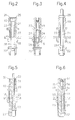
- FIG. 1 shows an axial one Longitudinal section through a pressure control valve device according to the invention and in FIGS. 2 to 6 are different Variants of the actuating device according to the invention also in the axial Middle section shown.
- valve housing 1 consists of a valve housing 1 with an input 2 for the primary pressure and an output 3 for the regulated secondary pressure. Between the input side and the output side an annular valve seat 4 is provided, which by a Valve body 5 is controlled. This is by a closing spring 6 in Direction loaded on the valve seat 4 and for pressure relief in one Cylinder 7 sealed out. On the opposite of the closing spring 6 On the side, the valve body 5 is firmly connected to a pin 8 which a boundary wall 9 of the valve housing 1 passes through and in one Membrane chamber 10 ends by opening a valve 11 in a membrane plate 12 controls. The membrane space 10 projects beyond the outlet 3 a channel 13 in connection.
- the valve housing 1 is cylindrical on its upper side Provided recess 14 which has a thread into which a Spring housing 15 is screwed.
- the spring housing 15 is stuck in the Recess 14 a control membrane 16 fixed on its outer circumference, the is loaded by a control spring 17 which has one end on the Membrane plate 12 rests. With its other end, the control spring is 17th supported on a spring plate 18, which is provided on an externally threaded Adjusting spindle 19 is screwed on.
- the adjusting spindle 19 passes through the spring housing 15 and is with a collar 20 on the inside of the Spring housing 15 supported.
- a cap-shaped handwheel 21 is attached in a rotationally fixed manner, with which the adjusting spindle 19 rotates and thus the spring plate 18th to change the bias of the control spring 17 are adjusted can.
- the adjustability of the spring plate 18 along the adjusting spindle 19 is limited by an end stop 22.
- the end stop 22 is also in turn Axial direction of the adjusting spindle 19 adjustable.
- one provided its own actuating device for its operation from outside the spring housing 15 is accessible and an adjustment of the end stop 22 between two end positions and a locking of the same at any point between the end positions. 1 is located the end stop 22 in the lowest end position, in which the maximum Biasing the control spring 17 is possible.
- the adjusting spindle 19 of the spring plate 18 with an axially continuous Channel 23 provided.
- the actuator for the end stop 22 has a channel which penetrates the channel 23 and is adjustable therein Rod on which the end stop 22 is provided and which in the individual embodiments is designed differently.
- the rod is designed as a screw 24, with a screw head 25 on a shoulder of the adjusting spindle 19th rotatably supported and by a flanged edge 26 of the adjusting spindle 19 is secured against falling out.
- the threaded one Screw 24 is slidable in a channel 23 of the adjusting spindle 19 guided sleeve 27 screwed, at the lower end of the Stop 22 is attached.
- the end stop 22 is adjusted by turning the screw 24 over the screw head 25, which after externally through that placed on the upper end of the adjusting spindle 19 Handwheel 21 is covered.
- the handwheel must be adjusted first 21 can be removed. This will result in an unintentional adjustment prevents the pressure regulator from being adjusted once.
- the stop 22 is designed as a pin in a continuous Cross bore of the sleeve 27 is attached laterally via the sleeve protrudes and in diametrically opposite longitudinal slots 28 of the adjusting spindle 19 is guided, whereby the sleeve 27 simultaneously in the adjusting spindle 19 is secured against twisting.
- the ends of the stop 22 forming pin also protrude beyond the adjusting spindle 19 and lie thus in the adjustment range of the spring plate 18.
- the spring plate 18 In Fig. 1 the spring plate 18 is in its uppermost end position, the control spring 17 has the smallest preload. Of the End stop 22, however, is shown in the lowest end position. Of the Spring plate 18 can therefore by turning the adjusting spindle 19 to Concerns at the stop 22 are screwed under, in which Position the control spring 17 has the greatest bias.
- the preload is the stop 22 by screwing in the screw 24 in the sleeve 27 in Fig. 1 upwards, which makes the adjustment of the spring plate 18 is restricted downwards.
- the adjustment of the pressure regulator shown in Fig. 1 by means of the adjusting spindle 19 and the screw 24 can advantageously during operation of the controller, i.e. under full medium pressure will.
- the handwheel 21 is then removed and the stop 22 by means of the screw 24 upwards adjusted until it strikes the spring plate 18. This is the adjustment ended and the handwheel 21 can be placed on the adjusting spindle 19 again will. It is then only possible to place the spring plate 18 between its uppermost end position and that fixed in an intermediate position End stop 22 to adjust so that the preselected maximum Biasing of the control spring 17 and thus the maximum secondary pressure cannot be exceeded.
- Fig. 2 in which the adjusting device essentially corresponds to the actuating device according to FIG. 1, are the spring plate 18 and the end stop 22 in the described an intermediate position corresponding to a preselected maximum pressure. It can be seen that the adjustment range of the spring plate 18th compared to the illustration in Fig. 1 due to the adjustment of the end stop 22 is limited. The pressure regulator can only work inside within the permissible range.
- FIGS. 3 to 6 are variants the actuating device, as in FIG. 2 only the actuating device is shown and the other parts of the pressure regulator, in particular also the rule spring are omitted.
- the spring plate 18 and the end stop 22 are also in intermediate positions in these exemplary embodiments shown, which are also set here according to the requirements can be.
- a screw 24 is provided, which in one end section with right-hand thread, in the other end section with left-hand thread is provided. It is with its lower end in one in the adjusting spindle 19 slidably guided sleeve 27 screwed and with its upper End in an internal thread provided in the channel 23 of the adjusting spindle 19.
- the stop 22 attached to the sleeve 27 is - just as in FIGS. 2 and 4 - guided in longitudinal slots 28 of the adjusting spindle 19 and can brought into an intermediate position by turning the screw 24 be in which he limits the adjustment of the spring plate 18.
- Fig. 4 is only one for the adjustment of the stop 22 Provided screw 24, and at the lower end of the end stop 22nd is attached which penetrates the entire length of the adjusting spindle 19.
- On the a screw nut 29 is screwed on at the upper end of the screw 24, which is supported on the adjusting spindle 19 and with the help of the screw 24 can be pulled up, taking the end stop 22 with it is and in the longitudinal slots 28 of the adjusting spindle 19th slides.
- the range of movement of the spring plate 18 also becomes corresponding with this limited, as can be seen from Fig. 4.
- 5 and 6 show embodiments in which Adjustment of the end stop 22 each has a rod 30 with a semicircular Cross section is provided at the lower end of the stop 22 is scheduled. 5 and 6, extends the stop 22 radially outwards only on one side of the rod 33 in the adjustment range of the spring plate 18. In the adjusting spindle 19 a longitudinal slot 28 is also provided here, in which the stop 22 is guided in its adjustment.
- the rod 30 has one Half threads existing screw thread 31.
- the adjusting spindle 19 at its upper end with a half gear existing screw thread 32 provided.
- a common nut 33 screwed, which the rod 30 with the end stop 22 fixed in the respective position.
- To adjust the Rod 30 is first unscrewed nut 33, whereupon the rod 30 steps up, each corresponding to a screw thread or can be moved below. This makes it possible to set the end stop 22 to bring in the desired intermediate position and the adjustment limit the spring plate 18. Then the Nut 33 screwed again and so the rod 30 with the end stop 22 fixed in the new position.
- an end stop can not only be applied to pressure regulating valves be, but also with other devices and devices, practical wherever a standard spring is preloaded.
- pressure relief valves, pressure balances and similar devices where the pressure of a pneumatic or hydraulic medium is determined by the preload of a control spring.
- safety valves which is based on a certain Pressure are set and one when this pressure is reached Open the relief path.
Abstract
Description
Die Erfindung bezieht sich auf eine Vorrichtung zur Begrenzung der Vorspannung einer Regelfeder, insbesondere der Regelfeder eines Druckregelventils, eines Druckentlastungsventils, einer Druckwaage od. dgl., bei der die Regelfeder in einem Federgehäuse angeordnet und an einem Federteller abgestützt ist, der auf eine mit Außengewinde versehene, durch ein aufgesetztes Handrad verdrehbare Stellspindel aufgeschraubt und im Federgehäuse gegen Verdrehen gesichert, aber axial verschiebbar gehalten ist, und wobei ein Endanschlag für den Federteller vorgesehen ist, der dessen Verstellung zur Vorspannung der Regelfeder begrenzt.The invention relates to a limiting device the bias of a control spring, in particular the control spring Pressure control valve, a pressure relief valve, a pressure compensator or Like., In which the control spring arranged in a spring housing and on a spring plate is supported on one with an external thread provided adjusting spindle which can be turned by a handwheel screwed on and secured in the spring housing against twisting, however is held axially displaceable, and wherein an end stop for the spring plate is provided, the adjustment of which to bias the Rule spring limited.
In der Regelungstechnik wird bekanntlich die Größe des geregelten Wertes, z.B. der Druck bei einem Druckregelventil, durch die von der Regelfeder ausgeübte Kraft bestimmt. Der gewünschte Wert wird durch die Veränderung der Vorspannung der Regelfeder eingestellt. Im Normalfall ist es dabei möglich, die Feder so weit vorzuspannen, bis die geregelte Größe den Maximalwert erreicht, im Falle eines Druckreglers also der geregelte Druck mit dem zugeführten Primärdruck übereinstimmt. In vielen Fällen ist dabei aus Sicherheitsgründen eine Begrenzung der geregelten Größe auf einen kleineren Wert erforderlich.As is well known in control engineering, the size of the controlled Value, e.g. the pressure at a pressure regulating valve by which the force exerted by the control spring is determined. The desired value is by changing the preload of the control spring. in the Normally, it is possible to preload the spring until the regulated size reaches the maximum value in the case of a pressure regulator thus the regulated pressure corresponds to the primary pressure supplied. In many cases there is a limitation for security reasons the regulated size to a smaller value.
Um eine Begrenzung der geregelten Größe zu ermöglichen, ist es bei der eingangs angeführten Vorrichtung bekannt, an der Stellspindel, mit der der Federteller zur Vorspannung der Regelfeder verstellbar ist, oder an einer sonstigen Einstellschraube für die Vorspannung einen festen Anschlag vorzusehen der die Verstellmöglichkeit zur Vorspannung der Regelfeder begrenzt. Dieser Anschlag ist serienmäßig oft an einer Stelle angebracht, an der er gerade verhindert, daß die Regelfeder auf Block gedrückt wird. Für Anwendungen, bei denen ein bestimmter kleinerer Wert gewünscht wird, muß bei der Herstellung der Vorrichtung der Anschlag an der entsprechend angepaßten Stelle angeordnet werden.It is to allow a limitation of the regulated size in the device mentioned at the beginning, on the adjusting spindle, with which the spring plate can be adjusted to preload the control spring, or on another adjusting screw for the preload to provide a firm stop for the adjustment option for pretensioning the rule spring is limited. This stop is often standard on one Place where he just prevents the control spring on Block is pressed. For applications where a certain a smaller value is required when manufacturing the device the stop can be arranged at the appropriately adapted point.
Bei Druckregelventilen sind zwei Ausführungen bekannt. Bei einer Ausführung werden die Spindellänge und der fixe Anschlag schon konstruktiv so ausgebildet oder angeordnet, daß die Regelfeder nur in dem vorbestimmten Ausmaß vorgespannt werden kann. Diese Ausführung ermöglicht eine normale Serienmontage. Es ergibt sich jedoch eine große Toleranz des erreichten Grenzwertes der Einstellung, da Längentoleranzen der Stellspindel, Federkrafttoleranzen und Toleranzen des wirksamen Membrandurchmessers einander addieren und zusammen den Grenzwert beeinflußen.Two versions of pressure control valves are known. At a Execution, the spindle length and the fixed stop are already constructive designed or arranged so that the control spring only in the predetermined extent can be biased. This execution enables normal series assembly. However, there is a big one Tolerance of the limit of the setting reached, because Length tolerances of the adjusting spindle, spring force tolerances and tolerances of the effective diaphragm diameter add up and together influence the limit.
Bei der zweiten Ausführung wird der Anschlag durch eine Anschlagmutter gebildet, die nach Justierung der gewünschten Vorspannung auf die Stellspindel aufgeschraubt wird, bis sie am Federteller anschlägt. Dabei ist eine genauere Druckbegrenzung möglich. Aber auch diese Begrenzung kann nur werksseitig erfolgen und nicht mehr nachträglich ohne weiteres geändert werden. Außerdem ist dabei eine teilweise Demontage der Vorrichtung nach der Justierung erforderlich, um die Anschlagmutter festzuschrauben. Anschließend muß der Durckregler nochmals geprüft werden, weil es möglich ist, daß die gewählte Vorspannung durch die Montagearbeiten verstellt wird.In the second version, the stop is made using a stop nut formed after adjusting the desired bias is screwed onto the adjusting spindle until it strikes the spring plate. A more precise pressure limitation is possible. But this limitation too can only be done at the factory and no longer afterwards can be easily changed. There is also a partial disassembly the device after the adjustment required to the stop nut screw tight. Then the pressure regulator must again be checked because it is possible that the selected preload is adjusted by the assembly work.
Der Erfindung liegt die Aufgabe zugrunde, die bisher bekannten Vorrichtungen zur Begrenzung der Vorspannung einer Regelfeder so zu verbessern, daß die Begrenzung auch vom Anwender des betreffenden Gerätes ohne aufwendige Montagearbeiten einfach und genau auf einen gewünschten Wert eingestellt werden kann. The invention has for its object the previously known Devices to limit the bias of a control spring so too improve that limitation also by the user of that Device without complex assembly work simply and precisely on one desired value can be set.
Mit der Erfindung wird diese Aufgabe bei der eingangs angeführten Vorrichtung dadurch gelöst, daß der Endanschlag für den Federteller im Federgehäuse in Achsrichtung der Stellspindel des Federtellers durch eine eigene Stellvorrichtung, die zu ihrer Betätigung von außerhalb des Federgehäuses zugänglich ist, zwischen zwei Endlagen verstellbar angeordnet und an beliebiger Stelle zwischen den Endlagen arretierbar ist. Bei dieser Ausbildung ist es möglich, bei vollständig montiertem Federgehäuse die Vorspannung der Regelfeder durch Verstellen des Federtellers mittels der Stellspindel auf den gewünschten oder maximal zulässigen Wert einzustellen und anschließend den Endanschlag mittels der eigenen Stellvorrichtung bis zu seinem Anliegen am Federteller zu verstellen und ihn an dieser Stelle zu fixieren. Die Vorspannung der Regelfeder kann dann mittels der Stellspindel jederzeit verringert, jedoch immer nur bis zum Anschlagen des Federtellers am Endanschlag erhöht werden. Da keine Montagearbeiten an der Vorrichtung selbst erforderlich sind, kann die gewünschte Vorspannung der Regelfeder jederzeit einfach eingestellt und auch verändert werden, wobei die Einstellung während des Betriebes der Vorrichtung erfolgen und daher laufend kontrolliert werden kann, so daß ohne störende Toleranzen stets der genaue Wert eingestellt wird.With the invention, this object is achieved in the above Device solved in that the end stop for the spring plate in the spring housing in the axial direction of the adjusting spindle of the spring plate by its own actuating device, which is used to operate it is accessible outside the spring housing, between two end positions adjustable and anywhere between the end positions can be locked. With this training it is possible to complete at mounted spring housing the preload of the control spring by adjusting the spring plate to the desired or using the adjusting spindle maximum permitted value and then the end stop by means of its own adjusting device until it rests on the spring plate to adjust and fix it at this point. The preload the control spring can then be reduced at any time using the adjusting spindle, however, only until the spring plate touches the end stop increase. Since no assembly work on the device itself are required, the desired preload of the control spring can be easily set and changed at any time, taking the setting take place during the operation of the device and therefore can be checked continuously, so that without disturbing tolerances the exact value is set.
Bei einer bevorzugten Ausführung der Erfindung ist die Stellspindel des Federtellers mit einem axial durchgehenden Kanal versehen und weist die Stellvorrichtung für den Anschlag eine den Kanal durchsetzende und in diesem verstellbare Stange auf, an der ein in den Verstellbereich des Federtellers ragender Anschlag vorgesehen ist. Die Einstellung der gewünschten Vorspannung der Regelfeder erfolgt dabei durch Verstellen der den Kanal durchsetzenden Stange, wodurch der Anschlag in die gewünschte Stellung gebracht wird. Außerdem zeichnet sich diese Ausführung dadurch aus, daß sie praktisch keinen zusätzlichen Raum beansprucht, weil die Stellvorrichtung für den Endanschlag im Inneren der Stellspindel untergebracht ist.In a preferred embodiment of the invention, the adjusting spindle the spring plate with an axially continuous channel and has the adjusting device for the stop penetrating the channel and in this adjustable rod on which one in the adjustment range of the spring plate projecting stop is provided. The setting the desired pre-tensioning of the control spring takes place by adjusting the rod passing through the channel, whereby the Stop is brought into the desired position. Also draws this version is characterized by the fact that it has practically none takes up additional space because the actuator for the end stop is housed inside the adjusting spindle.
Die Stange kann dabei in weiterer Ausgestaltung der Erfindung als Schraube ausgebildet sein, die im Kanal der Stellspindel drehbar verankert und in eine im Kanal geführte Hülse mit Innengewinde an einem Ende der Hülse eingeschraubt ist, an deren anderem Ende der Anschlag für den Federteller vorgesehen ist. Dabei erfolgt die Verstellung des Anschlages für den Federteller und damit die Einstellung der Vorspannung der Regelfeder durch einfaches Verdrehen der Schraube.The rod can in a further embodiment of the invention be designed as a screw that rotates in the channel of the adjusting spindle anchored and in a sleeve in the channel with an internal thread is screwed into one end of the sleeve, at the other end of which Stop for the spring plate is provided. The adjustment takes place the stop for the spring plate and thus the setting of the Preload the control spring by simply turning the screw.
Bei dieser Ausführung der Erfindung kann zur sicheren Halterung der Schraube diese mit einem Schraubenkopf auf einem Ansatz der Stellspindel drehbar gelagert und im Kanal der Stellspindel gegen Herausfallen gesichert sein, z.B. durch einen umgebördelten Rand der Stellspindel.This embodiment of the invention can be used for secure mounting the screw this with a screw head on a shoulder of the adjusting spindle rotatably mounted and in the channel of the adjusting spindle against falling out be secured, e.g. through a flanged edge of the adjusting spindle.
Nach einer weiteren Variante der Erfindung kann die Schraube von einem Ende ausgehend mit Rechtsgewinde und vom anderen Ende ausgehend mit Linksgewinde versehen sein, wobei sie mit einem Ende in den mit Innengewinde versehenen Kanal und mit dem anderen Ende in eine den Anschlag für den Federteller aufweisende Hülse eingeschraubt ist. Auch bei dieser Ausführung erfolgt die Verstellung des Anschlages für den Federteller durch bloses Verdrehen der im Kanal der Stellspindel vorgesehenen Schraube von außerhalb des Federgehäuses.According to a further variant of the invention, the screw from one end with right-hand thread and from the other end starting with left-hand thread, with one end in the internally threaded channel and the other end in screwed a sleeve having the stop for the spring plate is. The stop is also adjusted in this version for the spring plate by simply turning the in the channel of the adjusting spindle provided screw from outside the spring housing.
Erfindungsgemäß ist es weiterhin möglich, die als Schraube ausgeführte Stange an einem Ende mit Gewinde zu versehen, mit dem sie in ein Innengewinde des Kanals in der Stellspindel oder in eine an der Stellspindel abgestützte Schraubenmutter verstellbar eingeschraubt ist, wobei sie an ihrem anderen Ende den Anschlag für den Federteller aufweist. Zur Verstellung des Anschlages wird entweder die Stange in das Innengewinde des Kanals in der Stellspindel mehr oder weniger eingeschraubt oder einfach lediglich die Schraubenmutter betätigt, wodurch gleichfalls die Stange mit dem Endanschlag für den Federteller verstellt wird.According to the invention, it is also possible to design the screw To thread the rod at one end, with which it in an internal thread of the channel in the adjusting spindle or in one on the Adjusting screw supported screw nut is screwed adjustable, with the stop for the spring plate at its other end. To adjust the stop, either the rod in the Internal thread of the channel in the adjusting spindle more or less screwed in or simply actuated the screw nut, whereby likewise the rod with the end stop for the spring plate is adjusted.
Der Anschlag für den Federteller kann bei allen Ausführungsformen der Erfindung aus einem die Stange diametral durchsetzenden Stift bestehen, der mit seinen beiden Enden in Längsschlitzen der Stellspindel drehfest, jedoch axial verschiebbar geführt ist und über den Außenmantel der Stellspindel in den Verstellbereich des Federtellers vorragt. Dieser Anschlag ist einfach und mit geringem Aufwand herstellbar und ebenso leicht zu montieren; trotzdem erfüllt er einwandfrei seine Aufgabe, die Verstellung des Federtellers zur Vergrößerung der Vorspannung der Regelfeder zu begrenzen.The stop for the spring plate can be used in all embodiments of the invention from a diametrically penetrating the rod Pin exist, with its two ends in the longitudinal slots of the adjusting spindle rotatably, but is axially displaceable and over the Outer jacket of the adjusting spindle in the adjustment area of the spring plate protrudes. This stop is simple and can be produced with little effort and just as easy to assemble; nevertheless he fulfills his flawlessly Task, the adjustment of the spring plate to increase the preload limit the rule spring.
Im Rahmen der Erfindung ist eine weitere Ausführungsform möglich, bei der die den Anschlag für den Federteller aufweisende Stange mit halbkreisförmigem Querschnitt ausgebildet, im dazu passend ausgebildeten Kanal der Stellspindel axial verschiebbar geführt und an beliebiger Stelle arretierbar ist. Dabei ist die Stange im Kanal der Stellspindel gegen Verdrehen gesichert. Die Verstellung des Endanschlages erfolgt dabei nicht durch Verdrehen der Stange, sondern vielmehr durch Verschieben derselben in axialer Richtung im Kanal der Stellspindel. Dies kann auf verschiedene Weise erfolgen.A further embodiment is possible within the scope of the invention, in which the rod having the stop for the spring plate formed with a semicircular cross-section, in the matching trained Channel of the adjusting spindle guided axially displaceable and at any Is lockable. The rod is in the channel of the adjusting spindle secured against twisting. The end stop is adjusted not by turning the rod, but rather by moving it the same in the axial direction in the channel of the adjusting spindle. This can be done in different ways.
Eine Möglichkeit zum Verstellen der Stange im Kanal der Stellspindel besteht erfindungsgemäß darin, daß die Stange zu ihrer Verstellung und Arretierung an ihrem Außenmantel ein aus Halbgängen bestehendes Schraubengewinde aufweist, die Stellspindel an ihrem Ende mit einem spiegelbildlich dazu passenden Halbgewinde versehen ist und auf die beiden einander ergänzenden halben Schrauben eine gemeinsame Mutter aufgeschraubt ist. Die Mutter kann dabei abgenommen und die Stange mit halbkreisförmigem Querschnitt um einen oder mehrere Schraubengänge verschoben werden, worauf die Mutter zur Arretierung der Stange wieder aufgeschraubt wird. Dadurch ist es möglich, die Stange und mit dieser den Endanschlag für den Federteller jeweils in einem Schraubengang entsprechenden Schritten in beiden Längsrichtungen zu verstellen.One possibility for adjusting the rod in the channel of the adjusting spindle according to the invention is that the rod for its adjustment and locking on its outer jacket is a half course Has screw thread, the adjusting spindle at its end with a matching mirror thread is provided and on the two complementary half screws a common nut is screwed on. The mother can be removed and the rod with it semicircular cross section around one or more screw threads be moved, whereupon the mother to lock the rod again is screwed on. This makes it possible to use the rod and this the end stop for the spring plate each in a screw thread appropriate steps to adjust in both longitudinal directions.
Erfindungsgemäß ist alternativ vorgesehen, daß die Stange und die Stellspindel zur gegenseitigen Verstellung und zur Arretierung je mit einer halbkreisförmigen Rinne versehen sind und die beiden Rinnen zu einer vollen zylindrischen Bohrung zusammengesetzt sind, von der die eine Hälfte ein Gewinde aufweist, in das eine Wurmschraube eingreift, die in der anderen Hälfte der Bohrung drehbar, aber axial verschiebbar gelagert ist. Bei dieser Ausführung erfolgt die Verstellung der halbkreisförmigen Stange im Kanal der Stellspindel durch einfaches Verdrehen der Wurmschraube, wodurch gleichfalls die Stange verschoben und der Endanschlag für den Federteller in die gewünschte Stellung gebracht werden kann.According to the invention it is alternatively provided that the rod and the adjusting spindle for mutual adjustment and for locking each with are provided with a semicircular gutter and the two gutters too are composed of a full cylindrical bore, of which the one half has a thread into which a worm screw engages, the rotatable in the other half of the bore, but axially displaceable is stored. In this version, the semicircular is adjusted Rod in the channel of the adjusting spindle by simply turning it the worm screw, which also displaces the rod and the End stop for the spring plate brought into the desired position can be.
Schließlich sieht die Erfindung noch eine weitere Verbesserung vor, wonach die Stelle des Federgehäuses, an der die Stellvorrichtung für den Anschlag von außen zugänglich ist, durch das auf die Stellspindel zur Betätigung aufgesetzte Handrad abgedeckt ist. Es handelt sich dabei um eine Sicherheitsvorkehrung, die gewährleistet, daß die eingestellte Begrenzung der Vorspannkraft im späteren Betrieb nicht unabsichtlich und nicht ohne entsprechendes Werkzeug verändert werden kann. Trotzdem ist aber eine Änderung der Einstellung jederzeit möglich. Es muß lediglich vorher das Handrad abgenommen werden, worauf die Stellvorrichtung von außen zugänglich ist und mit einem passenden Werkzeug betätigt werden kann.Finally, the invention sees yet another improvement before which the point of the spring housing at which the adjusting device for the stop is accessible from the outside through the on the adjusting spindle handwheel attached for operation is covered. It is about a safety precaution that ensures that the set Limitation of the preload in unintentional operation and cannot be changed without the appropriate tools can. Nevertheless, the setting can be changed at any time. The handwheel only has to be removed beforehand, after which the Adjustment device is accessible from the outside and with a suitable tool can be operated.
Weitere Einzelheiten und Vorteile der Erfindung ergeben sich aus der nachfolgenden Beschreibung von Ausführungsbeispielen, die in den Zeichnungen dargestellt sind. In diesen zeigt Fig. 1 einen axialen Längsschnitt durch eine als Druckregelventil ausgeführte erfindungsgemäße Vorrichtung und in den Fig. 2 bis 6 sind verschiedene Varianten der erfindungsgemäßen Stellvorrichtung gleichfalls im axialen Mittelschnitt dargestellt.Further details and advantages of the invention result from the following description of exemplary embodiments, which in the Drawings are shown. 1 shows an axial one Longitudinal section through a pressure control valve device according to the invention and in FIGS. 2 to 6 are different Variants of the actuating device according to the invention also in the axial Middle section shown.
Das Druckregelventil nach Fig. 1 besteht aus einem Ventilgehäuse
1 mit einem Eingang 2 für den Primärdruck und einem Ausgang 3 für den
geregelten Sekundärdruck. Zwischen der Eingangsseite und der Ausgangsseite
ist ein ringförmiger Ventilsitz 4 vorgesehen, der durch einen
Ventilkörper 5 gesteuert ist. Dieser ist durch eine Schließfeder 6 in
Richtung auf den Ventilsitz 4 belastet und zur Druckentlastung in einem
Zylinder 7 abgedichtet geführt. Auf der der Schließfeder 6 gegenüberliegenden
Seite ist der Ventilkörper 5 mit einem Stift 8 fest verbunden, der
eine Begrenzungswand 9 des Ventilgehäuses 1 durchsetzt und in einem
Membranraum 10 endet, in dem er eine Ventilöffnung 11 in einem Membranteller
12 steuert. Der Membranraum 10 steht mit dem Ausgang 3 über
einen Kanal 13 in Verbindung.1 consists of a
Das Ventilgehäuse 1 ist an seiner Oberseite mit einer zylindrischen
Ausnehmung 14 versehen, die ein Gewinde aufweist, in das ein
Federgehäuse 15 eingeschraubt ist. Das Federgehäuse 15 klemmt in der
Ausnehmung 14 eine Regelmembran 16 an ihrem Außenumfang fest, die
durch eine Regelfeder 17 belastet ist, die mit dem einem Ende auf dem
Membranteller 12 aufliegt. Mit ihrem anderen Ende ist die Regelfeder 17
an einem Federteller 18 abgestützt, der auf eine mit Außengewinde versehende
Stellspindel 19 aufgeschraubt ist. Die Stellspindel 19 durchsetzt
das Federgehäuse 15 und ist mit einem Bund 20 an der Innenseite des
Federgehäuses 15 abgestützt. Auf das außenliegende Ende der Stellspindel
19 ist ein kappenförmig ausgebildetes Handrad 21 drehfest aufgesetzt,
mit dem die Stellspindel 19 verdreht und damit der Federteller 18
zur Veränderung der Vorspannung der Regelfeder 17 verstellt werden
kann. Die Verstellbarkeit des Federtellers 18 entlang der Stellspindel 19
ist durch einen Endanschlag 22 begrenzt.The
Um die Vorspannung der Regelfeder auf einen gewünschten maximalen
Wert zu begrenzen, ist der Endanschlag 22 seinerseits ebenfalls in
Achsrichtung der Stellspindel 19 verstellbar. Zu diesem Zweck ist eine
eigene Stellvorrichtung vorgesehen, die zu ihrer Betätigung von außerhalb
des Federgehäuses 15 zugänglich ist und eine Verstellung des Endanschlages
22 zwischen zwei Endlagen sowie eine Arretierung desselben
an beliebiger Stelle zwischen den Endlagen ermöglicht. In Fig. 1 befindet
sich der Endanschlag 22 in der untersten Endlage, in der die maximale
Vorspannung der Regelfeder 17 möglich ist.To bias the control spring to a desired maximum
To limit the value, the
Wie aus Fig. 1 und auch aus den Fig. 2 bis 6 entnommen werden
kann, ist die Stellspindel 19 des Federtellers 18 mit einem axial durchgehenden
Kanal 23 versehen. Die Stellvorrichtung für den Endanschlag
22 weist eine den Kanal 23 durchsetzende und in diesem verstellbare
Stange auf, an der der Endanschlag 22 vorgesehen ist und die in den
einzelnen Ausführungsbeispielen unterschiedlich ausgebildet ist.As can be seen from FIG. 1 and also from FIGS. 2 to 6
can, the adjusting
Gemäß den Fig. 1 und 2 ist die Stange als Schraube 24 ausgebildet,
die mit einem Schraubenkopf 25 auf einem Ansatz der Stellspindel 19
drehbar gelagert und durch einen umgebördelten Rand 26 der Stellspindel
19 gegen Herausfallen gesichert ist. Die mit Gewinde versehene
Schraube 24 ist in eine gleichfalls im Kanal 23 der Stellspindel 19 verschiebbar
geführte Hülse 27 eingeschraubt, an deren unterem Ende der
Anschlag 22 befestigt ist. Die Verstellung des Endanschlages 22 erfolgt
durch Verdrehen der Schraube 24 über den Schraubenkopf 25, der nach
außen durch das auf das obere Ende der Stellspindel 19 aufgesetzte
Handrad 21 abgedeckt ist. Zur Verstellung muß also zunächst das Handrad
21 abgenommen werden. Dadurch wird eine unbeabsichtigte Verstellung
der einmal vorgenommenen Justierung des Druckreglers verhindert. 1 and 2, the rod is designed as a
Der Anschlag 22 ist als Stift ausgeführt, der in einer durchgehenden
Querbohrung der Hülse 27 befestigt ist, über die Hülse seitlich
vorragt und in diametral gegenüberliegenden Längsschlitzen 28 der Stellspindel
19 geführt ist, wodurch die Hülse 27 gleichzeitig in der Stellspindel
19 gegen Verdrehen gesichert ist. Die Enden des den Anschlag
22 bildenden Stiftes ragen auch über die Stellspindel 19 vor und liegen
damit im Verstellbereich des Federtellers 18.The
In Fig. 1 befindet sich der Federteller 18 in seiner obersten Endlage,
wobei die Regelfeder 17 die kleinste Vorspannung aufweist. Der
Endanschlag 22 ist dagegen in der untersten Endlage dargestellt. Der
Federteller 18 kann daher durch Verdrehen der Stellspindel 19 bis zum
Anliegen am Anschlag 22 nach unter geschraubt werden, in welcher
Stellung die Regelfeder 17 die größte Vorspannung hat. Zur Begrenzung
der Vorspannung wird der Anschlag 22 durch Einschrauben der Schraube
24 in die Hülse 27 in Fig. 1 nach oben verstellt, wodurch die Verstellmöglichkeit
des Federtellers 18 nach unten eingeschränkt wird.In Fig. 1 the
Die Justierung des in Fig. 1 dargestellten Druckreglers mittels
der Stellspindel 19 und der Schraube 24 kann in vorteilhafter Weise während
des Betriebes des Reglers, also unter vollem Mediumsdruck, vorgenommen
werden. Zunächst wird der Sekundärdruck am Ausgang 3 durch
Verdrehen der Stellspindel 19 mittels des Handrades 21, wodurch die
Regelfeder 17 über den Federteller 18 vorgespannt wird auf den gewünschten
maximal zulässigen Wert eingestellt. Das Handrad 21 wird dann
abgenommen und der Anschlag 22 mittels der Schraube 24 nach oben
verstellt, bis er am Federteller 18 anschlägt. Damit ist die Justierung
beendet und das Handrad 21 kann wieder auf die Stellspindel 19 aufgesetzt
werden. Es ist dann nur noch möglich, den Federteller 18 zwischen
seiner obersten Endlage und dem in einer Zwischenstellung fixierten
Endanschlag 22 zu verstellen, so daß die vorgewählte maximale
Vorspannung der Regelfeder 17 und damit der maximale Sekundärdruck
nicht überschritten werden können.The adjustment of the pressure regulator shown in Fig. 1 by means of
the adjusting
Bei der in Fig. 2 gezeigten Ausführung, bei der die Stellvorrichtung
im wesentlichen mit der Stellvorrichtung nach Fig. 1 übereinstimmt,
befinden sich der Federteller 18 und der Endanschlag 22 in der beschriebenen,
einem vorgewählten Maximaldruck entsprechenden Zwischenstellung.
Es ist zu erkennen, daß der Verstellbereich des Federtellers 18
gegenüber der Darstellung in Fig. 1 aufgrund der Verstellung des Endanschlages
22 begrenzt ist. Der Druckregler kann also nur mehr innerhalb
des zulässigen Bereichs verstellt werden.In the embodiment shown in Fig. 2, in which the adjusting device
essentially corresponds to the actuating device according to FIG. 1,
are the
Die Ausführungsbeispiele nach den Fig. 3 bis 6 sind Varianten
der Stellvorrichtung, wobei wie in Fig. 2 lediglich die Stellvorrichtung
dargestellt ist und die übrigen Teile des Druckreglers, insbesondere
auch die Regelfeder, weggelassen sind. Der Federteller 18 und der Endanschlag
22 sind auch in diesen Ausführungsbeispielen in Zwischenstellungen
dargestellt, die auch hier den Anforderungen entsprechend eingestellt
werden können.The exemplary embodiments according to FIGS. 3 to 6 are variants
the actuating device, as in FIG. 2 only the actuating device
is shown and the other parts of the pressure regulator, in particular
also the rule spring are omitted. The
Im Ausführungsbeispiel nach Fig. 3 ist für die Verstellung des
Endanschlages 22 eine Schraube 24 vorgesehen, die in einem Endabschnitt
mit Rechtsgewinde, im anderen Endabschnitt mit Linksgewinde
versehen ist. Sie ist mit ihrem unteren Ende in eine in der Stellspindel
19 verschiebbar geführte Hülse 27 eingeschraubt und mit ihrem oberen
Ende in ein im Kanal 23 der Stellspindel 19 vorgesehenes Innengewinde.
Der an der Hülse 27 befestigte Anschlag 22 ist - ebenso wie in den Fig.
2 und 4 - in Längsschlitzen 28 der Stellspindel 19 geführt und kann
durch Verdrehen der Schraube 24 in eine Zwischenstellung gebracht
werden, in der er die Verstellung des Federtellers 18 begrenzt.3 is for the adjustment of the
End stop 22 a
In Fig. 4 ist für die Verstellung des Anschlages 22 lediglich eine
Schraube 24 vorgesehen, und an deren unterem Ende der Endanschlag 22
befestigt ist die die ganze Länge der Stellspindel 19 durchsetzt. Auf das
obere Ende der Schraube 24 ist eine Schraubenmutter 29 aufgeschraubt,
die sich an der Stellspindel 19 abstützt und mit deren Hilfe die Schraube
24 nach oben gezogen werden kann, wobei der Endanschlag 22 mitgenommen
wird und dabei in den Längsschlitzen 28 der Stellspindel 19
gleitet. Auch damit wird der Bewegungsbereich des Federtellers 18 entsprechend
eingeschränkt, wie aus Fig. 4 zu erkennen ist.In Fig. 4 is only one for the adjustment of the
Die Fig. 5 und 6 zeigen Ausführungsbeispiele, bei denen zur
Verstellung des Endanschlages 22 jeweils eine Stange 30 mit halbkreisförmigem
Querschnitt vorgesehen ist, an deren unterem Ende der Anschlag
22 angesetzt ist. Wie aus den Fig. 5 und 6 hervorgeht, erstreckt sich
dabei der Anschlag 22 nur auf einer Seite von der Stange 33 radial auswärts
in den Verstellbereich des Federtellers 18. In der Stellspindel 19
ist auch hier jeweils ein Längsschlitz 28 vorgesehen, in dem der Anschlag
22 bei seiner Verstellung geführt ist.5 and 6 show embodiments in which
Adjustment of the
Im Ausführungsbeispiel nach Fig. 5 weist die Stange 30 ein aus
Halbgängen bestehendes Schraubengewinde 31 auf. Spiegelbildlich dazu
ist auch die Stellspindel 19 an ihrem oberen Ende mit einem aus Halbgängen
bestehenden Schraubengewinde 32 versehen. Auf die beiden Halbgewinde
ist eine gemeinsame Mutter 33 aufgeschraubt, die die Stange 30 mit
dem Endanschlag 22 in der jeweiligen Stellung fixiert. Zum Verstellen der
Stange 30 wird zunächst die Mutter 33 abgeschraubt, worauf die Stange
30 um Schritte, die jeweils einem Schraubengang entsprechen, nach oben
oder unten verschoben werden kann. Dadurch ist es möglich, den Endanschlag
22 in die gewünschte Zwischenstellung zu bringen und die Verstellmöglichkeit
des Federtellers 18 zu begrenzen. Anschließend wird die
Mutter 33 wieder aufgeschraubt und so die Stange 30 mit dem Endanschlag
22 in der neuen Stellung fixiert. In the exemplary embodiment according to FIG. 5, the
Beim Ausführungsbeispiel nach Fig. 6 ist die Verstellung der
Stange 30 etwas einfacher. Dort sind die Stellspindel 19 und die Stange
30 in ihren oberen Teilen mit je einer halbkreisförmigen Rinne 34, 35
versehen, die einander zugekehrt sind und zusammen eine volle zylindrische
Bohrung bilden. Die halbkreisförmige Rinne 34 in der Stange 30
ist mit einem Innengewinde 36 versehen, in das eine Wurmschraube 37
eingreift, die in der halbkreisförmigen Rinne 35 in der Stellspindel 19
frei drehbar gelagert ist. Durch Verdrehen der Wurmschraube 37 kann
die Stange 30 mit dem Endanschlag 22 in Achsrichtung der Stellspindel 19
verstellt werden.6 is the adjustment of the
Bar 30 a little easier. There are the adjusting
Die erfindungsgemäße Stellvorrichtung zur wahlweisen Verstellung eines Endanschlages kann nicht nur bei Druckregelventilen angewendet werden, sondern auch bei anderen Geräten und Vorrichtungen, praktisch überall dort, wo eine Regelfeder vorgespannt wird. Insbesondere zu erwähnen sind Druckentlastungsventile, Druckwaagen und ähnliche Geräte, bei denen der Druck eines pneumatischen oder hydraulischen Mediums durch die Vorspannung einer Regelfeder bestimmt wird. Weiters ist eine Anwendung bei Sicherheitsventilen denkbar, die auf einen bestimmten Druck eingestellt sind und beim Erreichen dieses Druckes einen Entlastungsweg öffnen.The adjusting device according to the invention for optional adjustment an end stop can not only be applied to pressure regulating valves be, but also with other devices and devices, practical wherever a standard spring is preloaded. In particular, too mentioned are pressure relief valves, pressure balances and similar devices, where the pressure of a pneumatic or hydraulic medium is determined by the preload of a control spring. Furthermore is an application in safety valves conceivable, which is based on a certain Pressure are set and one when this pressure is reached Open the relief path.
Claims (11)
Applications Claiming Priority (3)
| Application Number | Priority Date | Filing Date | Title |
|---|---|---|---|
| AT0113096A AT405675B (en) | 1996-06-26 | 1996-06-26 | DEVICE FOR LIMITING THE PRELOADING OF A REGULATING SPRING |
| AT113096 | 1996-06-26 | ||
| AT1130/96 | 1996-06-26 |
Publications (3)
| Publication Number | Publication Date |
|---|---|
| EP0816730A2 true EP0816730A2 (en) | 1998-01-07 |
| EP0816730A3 EP0816730A3 (en) | 1998-09-23 |
| EP0816730B1 EP0816730B1 (en) | 2002-11-06 |
Family
ID=3507249
Family Applications (1)
| Application Number | Title | Priority Date | Filing Date |
|---|---|---|---|
| EP19970890107 Expired - Lifetime EP0816730B1 (en) | 1996-06-26 | 1997-06-19 | Device for limiting the prestress of a control spring |
Country Status (5)
| Country | Link |
|---|---|
| US (1) | US5924443A (en) |
| EP (1) | EP0816730B1 (en) |
| AT (2) | AT405675B (en) |
| DE (1) | DE59708651D1 (en) |
| ES (1) | ES2186861T3 (en) |
Cited By (2)
| Publication number | Priority date | Publication date | Assignee | Title |
|---|---|---|---|---|
| CN101201128B (en) * | 2007-11-14 | 2010-06-09 | 宁波亚德客自动化工业有限公司 | Pressure regulating valve |
| DE102011056763B3 (en) * | 2011-12-21 | 2013-02-21 | Goetze Kg Armaturen | Safety valve, has handle formed by cap of valve cover, where handle is axially displaceable inside engagement portion, and end portion of adjusting spindle is mounted integrally with engaging mating section |
Families Citing this family (12)
| Publication number | Priority date | Publication date | Assignee | Title |
|---|---|---|---|---|
| JPH1162842A (en) * | 1997-08-08 | 1999-03-05 | Toyota Autom Loom Works Ltd | Displacement control valve of variable displacement compressor |
| DE10002752C1 (en) * | 2000-01-22 | 2001-06-21 | Festo Ag & Co | Pressure regulating valve with secondary venting provided via venting opening in movable setting element communicating directly with secondary channel for regulated secondary pressure |
| ITRE20010030A1 (en) * | 2001-03-29 | 2002-09-29 | Sacmi Forni Spa | DEVICE FOR ADJUSTING THE COMBUSTION RATIO OF THE FUEL MIXTURE FOR THE BURNERS OF THE GAS OVENS |
| EP1279875A3 (en) * | 2001-07-23 | 2003-04-09 | Vaillant GmbH | Method for dimensioning a spring loaded valve and valve made according to this method |
| US7467778B2 (en) * | 2003-09-15 | 2008-12-23 | Exxonmobil Upstream Research Company | Slurry tolerant pilot operated relief valve |
| DE102005036553A1 (en) * | 2005-05-30 | 2006-12-07 | Bosch Rexroth Aktiengesellschaft | Valve e.g. pressure control valve, adjusting mechanism for machine tool, has locking collar which is brought by relative movement in axial locking position to lock handle with actuator in axial direction |
| CN102147027A (en) * | 2010-10-12 | 2011-08-10 | 杭州春江阀门有限公司 | Adjustable pressure-relieving/holding valve |
| KR101398444B1 (en) * | 2013-11-06 | 2014-05-27 | 주식회사 코베아 | Valve |
| JP2016170748A (en) * | 2015-03-16 | 2016-09-23 | アズビル株式会社 | Decompression valve |
| DE102015007689A1 (en) * | 2015-06-11 | 2016-12-15 | Hydac Fluidtechnik Gmbh | Pressure control valve |
| GB2585035B (en) * | 2019-06-25 | 2023-04-26 | Intersurgical Ag | An adjustable valve |
| CN115773394B (en) * | 2023-02-13 | 2023-05-02 | 通威微电子有限公司 | Residual pressure valve and air conditioning chamber |
Citations (5)
| Publication number | Priority date | Publication date | Assignee | Title |
|---|---|---|---|---|
| US4284102A (en) * | 1978-06-28 | 1981-08-18 | H. Adler Associates, Inc. | Combination stop and pressure reducing valve |
| US4760862A (en) * | 1986-02-17 | 1988-08-02 | Ckd Kabushiki Kaisha | Air pressure regulator |
| US5082019A (en) * | 1991-03-27 | 1992-01-21 | Aerodyne Controls Corporation | Calibrated quick setting mechanism for air pressure regulator |
| US5452741A (en) * | 1993-10-01 | 1995-09-26 | Smc Kabushiki Kaisha | Pressure reducing valve |
| EP0681126A1 (en) * | 1994-05-06 | 1995-11-08 | Hans Sasserath & Co Kg | Tension adjusting device for the spring of a spring loaded valve |
Family Cites Families (15)
| Publication number | Priority date | Publication date | Assignee | Title |
|---|---|---|---|---|
| DE7419848U (en) * | 1975-07-03 | Hansa Metallwerke Ag | Safety valve | |
| US1288821A (en) * | 1917-04-28 | 1918-12-24 | Thomas William Broderick | Air safety-valve. |
| US3068883A (en) * | 1960-04-27 | 1962-12-18 | Grove Valve & Regulator Co | Regulator |
| US3013790A (en) * | 1960-08-10 | 1961-12-19 | Gen Electric | Pressure regulating valve adjustment mechanism |
| US3451421A (en) * | 1966-07-22 | 1969-06-24 | Controls Co Of America | Convertible modulating pressure regulator |
| DE2447999C2 (en) * | 1974-10-09 | 1985-06-13 | Robert Bosch Gmbh, 7000 Stuttgart | Multi-position multi-way valve |
| DE2926522C2 (en) * | 1979-06-30 | 1983-10-06 | Bopp & Reuther Gmbh, 6800 Mannheim | Spring-loaded safety valve |
| DE3303872A1 (en) * | 1983-02-05 | 1984-08-09 | NEUMO Apparatebau, Metallgießerei GmbH, 7134 Knittlingen | Operating device for a pivotable valve body of a valve |
| DE3342427A1 (en) * | 1983-11-24 | 1985-06-05 | Alfred Teves Gmbh, 6000 Frankfurt | PRESSURE VALVE |
| DE3538828A1 (en) * | 1985-10-31 | 1987-05-07 | Druva Gmbh | BASIC FITTINGS, PARTICULARLY AS PART OF A PRESSURE REDUCER |
| US4696320A (en) * | 1986-12-05 | 1987-09-29 | Wilkerson Corporation | Pressure control valve with push-pull locking adjustment knob |
| DE8707357U1 (en) * | 1987-05-22 | 1987-09-03 | Erwes, Ralf Peter, 4600 Dortmund, De | |
| US5060690A (en) * | 1990-07-23 | 1991-10-29 | Ykk Corporation | Pre-set regulator assembly |
| DE4108080C2 (en) * | 1991-03-13 | 2001-08-30 | Bosch Gmbh Robert | Pressure control valve |
| DE4206125A1 (en) * | 1992-02-27 | 1993-09-02 | Sempell Babcock Ag | VALVE, ESPECIALLY SAFETY VALVE |
-
1996
- 1996-06-26 AT AT0113096A patent/AT405675B/en not_active IP Right Cessation
-
1997
- 1997-06-19 DE DE59708651T patent/DE59708651D1/en not_active Expired - Fee Related
- 1997-06-19 AT AT97890107T patent/ATE227401T1/en not_active IP Right Cessation
- 1997-06-19 EP EP19970890107 patent/EP0816730B1/en not_active Expired - Lifetime
- 1997-06-19 ES ES97890107T patent/ES2186861T3/en not_active Expired - Lifetime
- 1997-06-26 US US08/883,169 patent/US5924443A/en not_active Expired - Fee Related
Patent Citations (5)
| Publication number | Priority date | Publication date | Assignee | Title |
|---|---|---|---|---|
| US4284102A (en) * | 1978-06-28 | 1981-08-18 | H. Adler Associates, Inc. | Combination stop and pressure reducing valve |
| US4760862A (en) * | 1986-02-17 | 1988-08-02 | Ckd Kabushiki Kaisha | Air pressure regulator |
| US5082019A (en) * | 1991-03-27 | 1992-01-21 | Aerodyne Controls Corporation | Calibrated quick setting mechanism for air pressure regulator |
| US5452741A (en) * | 1993-10-01 | 1995-09-26 | Smc Kabushiki Kaisha | Pressure reducing valve |
| EP0681126A1 (en) * | 1994-05-06 | 1995-11-08 | Hans Sasserath & Co Kg | Tension adjusting device for the spring of a spring loaded valve |
Cited By (2)
| Publication number | Priority date | Publication date | Assignee | Title |
|---|---|---|---|---|
| CN101201128B (en) * | 2007-11-14 | 2010-06-09 | 宁波亚德客自动化工业有限公司 | Pressure regulating valve |
| DE102011056763B3 (en) * | 2011-12-21 | 2013-02-21 | Goetze Kg Armaturen | Safety valve, has handle formed by cap of valve cover, where handle is axially displaceable inside engagement portion, and end portion of adjusting spindle is mounted integrally with engaging mating section |
Also Published As
| Publication number | Publication date |
|---|---|
| DE59708651D1 (en) | 2002-12-12 |
| AT405675B (en) | 1999-10-25 |
| ATA113096A (en) | 1999-02-15 |
| US5924443A (en) | 1999-07-20 |
| EP0816730B1 (en) | 2002-11-06 |
| ES2186861T3 (en) | 2003-05-16 |
| ATE227401T1 (en) | 2002-11-15 |
| EP0816730A3 (en) | 1998-09-23 |
Similar Documents
| Publication | Publication Date | Title |
|---|---|---|
| AT405675B (en) | DEVICE FOR LIMITING THE PRELOADING OF A REGULATING SPRING | |
| DE2056072A1 (en) | Thermostatically controlled mixing valve for hot and cold water | |
| EP0751448A2 (en) | Flow control valve | |
| DE2124120A1 (en) | Brake actuator | |
| EP0688984A1 (en) | Diaphragm valve | |
| WO2003014570A1 (en) | Valve block for a control device, particularly for a hydrostatic machine | |
| DE1750046A1 (en) | Adjustable switching valve | |
| EP3447346A1 (en) | Valve, in particular servo valve | |
| DE2515019C2 (en) | Piston-cylinder unit for an adjusting or working device | |
| DE3814248A1 (en) | ADJUSTABLE CHECK VALVE | |
| DE1932521A1 (en) | Pressure regulator | |
| DE2831733B2 (en) | ||
| EP3540129B1 (en) | Sanitary fitting | |
| CH641260A5 (en) | Pressure control (relief) valve for hydraulic control systems | |
| DE102010023574A1 (en) | Angle valve for use in connector of water heater for regulating volume stream of water, has seal designed as sealing plug, and flow controller arranged in housing comprising ring that is positioned in borehole in sealed manner | |
| EP0758063B1 (en) | Starting valve for pneumatic systems | |
| DE2158950A1 (en) | THERMOSTATIC RADIATOR VALVE | |
| DE1125295B (en) | Hydraulic power steering for motor vehicles | |
| DE102018206045B3 (en) | Rotary handle device and sanitary valve | |
| EP1705410B1 (en) | Throttle valve | |
| EP0745042B1 (en) | Power steering for motor vehicles | |
| DE102007022059A1 (en) | Lifting magnet arrangement for solenoid valve, has adjusting device adjusting prestress of spring device, where spring device acting on anchor piston axially against drive force is accommodated in central borehole | |
| DE202004002987U1 (en) | Compressed air maintenance device has pressure regulator with telescopic rotatable adjusting knob with coupling component engaging with adjusting spindle, and operating component adjustable relative to coupling component | |
| DE1427430C3 (en) | Servo control of a press drive consisting of clutch and brake | |
| DE2905799C2 (en) | Pneumatic positioner with spiral measuring spring |
Legal Events
| Date | Code | Title | Description |
|---|---|---|---|
| PUAI | Public reference made under article 153(3) epc to a published international application that has entered the european phase |
Free format text: ORIGINAL CODE: 0009012 |
|
| AK | Designated contracting states |
Kind code of ref document: A2 Designated state(s): AT DE ES FR GB IT SE |
|
| PUAL | Search report despatched |
Free format text: ORIGINAL CODE: 0009013 |
|
| AK | Designated contracting states |
Kind code of ref document: A3 Designated state(s): AT BE CH DE DK ES FI FR GB GR IE IT LI LU MC NL PT SE |
|
| 17P | Request for examination filed |
Effective date: 19990304 |
|
| AKX | Designation fees paid |
Free format text: AT DE ES FR GB IT SE |
|
| RBV | Designated contracting states (corrected) |
Designated state(s): AT DE ES FR GB IT SE |
|
| RAP1 | Party data changed (applicant data changed or rights of an application transferred) |
Owner name: HYGRAMA AG |
|
| 17Q | First examination report despatched |
Effective date: 20010817 |
|
| GRAG | Despatch of communication of intention to grant |
Free format text: ORIGINAL CODE: EPIDOS AGRA |
|
| GRAG | Despatch of communication of intention to grant |
Free format text: ORIGINAL CODE: EPIDOS AGRA |
|
| GRAH | Despatch of communication of intention to grant a patent |
Free format text: ORIGINAL CODE: EPIDOS IGRA |
|
| GRAH | Despatch of communication of intention to grant a patent |
Free format text: ORIGINAL CODE: EPIDOS IGRA |
|
| GRAA | (expected) grant |
Free format text: ORIGINAL CODE: 0009210 |
|
| AK | Designated contracting states |
Kind code of ref document: B1 Designated state(s): AT DE ES FR GB IT SE |
|
| REF | Corresponds to: |
Ref document number: 227401 Country of ref document: AT Date of ref document: 20021115 Kind code of ref document: T |
|
| REG | Reference to a national code |
Ref country code: GB Ref legal event code: FG4D Free format text: NOT ENGLISH |
|
| GBT | Gb: translation of ep patent filed (gb section 77(6)(a)/1977) |
Effective date: 20021106 |
|
| REF | Corresponds to: |
Ref document number: 59708651 Country of ref document: DE Date of ref document: 20021212 |
|
| REG | Reference to a national code |
Ref country code: ES Ref legal event code: FG2A Ref document number: 2186861 Country of ref document: ES Kind code of ref document: T3 |
|
| PGFP | Annual fee paid to national office [announced via postgrant information from national office to epo] |
Ref country code: FR Payment date: 20030523 Year of fee payment: 7 |
|
| PGFP | Annual fee paid to national office [announced via postgrant information from national office to epo] |
Ref country code: DE Payment date: 20030528 Year of fee payment: 7 |
|
| PGFP | Annual fee paid to national office [announced via postgrant information from national office to epo] |
Ref country code: SE Payment date: 20030604 Year of fee payment: 7 |
|
| PGFP | Annual fee paid to national office [announced via postgrant information from national office to epo] |
Ref country code: ES Payment date: 20030606 Year of fee payment: 7 |
|
| PGFP | Annual fee paid to national office [announced via postgrant information from national office to epo] |
Ref country code: GB Payment date: 20030618 Year of fee payment: 7 |
|
| PG25 | Lapsed in a contracting state [announced via postgrant information from national office to epo] |
Ref country code: AT Free format text: LAPSE BECAUSE OF NON-PAYMENT OF DUE FEES Effective date: 20030619 |
|
| ET | Fr: translation filed | ||
| PLBE | No opposition filed within time limit |
Free format text: ORIGINAL CODE: 0009261 |
|
| STAA | Information on the status of an ep patent application or granted ep patent |
Free format text: STATUS: NO OPPOSITION FILED WITHIN TIME LIMIT |
|
| 26N | No opposition filed |
Effective date: 20030807 |
|
| PG25 | Lapsed in a contracting state [announced via postgrant information from national office to epo] |
Ref country code: GB Free format text: LAPSE BECAUSE OF NON-PAYMENT OF DUE FEES Effective date: 20040619 |
|
| PG25 | Lapsed in a contracting state [announced via postgrant information from national office to epo] |
Ref country code: SE Free format text: LAPSE BECAUSE OF NON-PAYMENT OF DUE FEES Effective date: 20040620 |
|
| PG25 | Lapsed in a contracting state [announced via postgrant information from national office to epo] |
Ref country code: ES Free format text: LAPSE BECAUSE OF NON-PAYMENT OF DUE FEES Effective date: 20040621 |
|
| PG25 | Lapsed in a contracting state [announced via postgrant information from national office to epo] |
Ref country code: DE Free format text: LAPSE BECAUSE OF NON-PAYMENT OF DUE FEES Effective date: 20050101 |
|
| EUG | Se: european patent has lapsed | ||
| EUG | Se: european patent has lapsed | ||
| GBPC | Gb: european patent ceased through non-payment of renewal fee |
Effective date: 20040619 |
|
| PG25 | Lapsed in a contracting state [announced via postgrant information from national office to epo] |
Ref country code: FR Free format text: LAPSE BECAUSE OF NON-PAYMENT OF DUE FEES Effective date: 20050228 |
|
| REG | Reference to a national code |
Ref country code: FR Ref legal event code: ST |
|
| PG25 | Lapsed in a contracting state [announced via postgrant information from national office to epo] |
Ref country code: IT Free format text: LAPSE BECAUSE OF NON-PAYMENT OF DUE FEES Effective date: 20050619 |
|
| REG | Reference to a national code |
Ref country code: ES Ref legal event code: FD2A Effective date: 20040621 |