EP0816726B1 - Bürstendichtungen und kombinierte Labyrinth- und Bürstendichtungen für drehende Maschinen - Google Patents
Bürstendichtungen und kombinierte Labyrinth- und Bürstendichtungen für drehende Maschinen Download PDFInfo
- Publication number
- EP0816726B1 EP0816726B1 EP19970304685 EP97304685A EP0816726B1 EP 0816726 B1 EP0816726 B1 EP 0816726B1 EP 19970304685 EP19970304685 EP 19970304685 EP 97304685 A EP97304685 A EP 97304685A EP 0816726 B1 EP0816726 B1 EP 0816726B1
- Authority
- EP
- European Patent Office
- Prior art keywords
- seal
- bristles
- labyrinth
- teeth
- array
- Prior art date
- Legal status (The legal status is an assumption and is not a legal conclusion. Google has not performed a legal analysis and makes no representation as to the accuracy of the status listed.)
- Revoked
Links
Images


Classifications
-
- F—MECHANICAL ENGINEERING; LIGHTING; HEATING; WEAPONS; BLASTING
- F16—ENGINEERING ELEMENTS AND UNITS; GENERAL MEASURES FOR PRODUCING AND MAINTAINING EFFECTIVE FUNCTIONING OF MACHINES OR INSTALLATIONS; THERMAL INSULATION IN GENERAL
- F16J—PISTONS; CYLINDERS; SEALINGS
- F16J15/00—Sealings
- F16J15/16—Sealings between relatively-moving surfaces
- F16J15/32—Sealings between relatively-moving surfaces with elastic sealings, e.g. O-rings
- F16J15/3284—Sealings between relatively-moving surfaces with elastic sealings, e.g. O-rings characterised by their structure; Selection of materials
- F16J15/3288—Filamentary structures, e.g. brush seals
-
- F—MECHANICAL ENGINEERING; LIGHTING; HEATING; WEAPONS; BLASTING
- F01—MACHINES OR ENGINES IN GENERAL; ENGINE PLANTS IN GENERAL; STEAM ENGINES
- F01D—NON-POSITIVE DISPLACEMENT MACHINES OR ENGINES, e.g. STEAM TURBINES
- F01D11/00—Preventing or minimising internal leakage of working-fluid, e.g. between stages
- F01D11/02—Preventing or minimising internal leakage of working-fluid, e.g. between stages by non-contact sealings, e.g. of labyrinth type
-
- F—MECHANICAL ENGINEERING; LIGHTING; HEATING; WEAPONS; BLASTING
- F01—MACHINES OR ENGINES IN GENERAL; ENGINE PLANTS IN GENERAL; STEAM ENGINES
- F01D—NON-POSITIVE DISPLACEMENT MACHINES OR ENGINES, e.g. STEAM TURBINES
- F01D11/00—Preventing or minimising internal leakage of working-fluid, e.g. between stages
- F01D11/08—Preventing or minimising internal leakage of working-fluid, e.g. between stages for sealing space between rotor blade tips and stator
- F01D11/12—Preventing or minimising internal leakage of working-fluid, e.g. between stages for sealing space between rotor blade tips and stator using a rubstrip, e.g. erodible. deformable or resiliently-biased part
-
- F—MECHANICAL ENGINEERING; LIGHTING; HEATING; WEAPONS; BLASTING
- F16—ENGINEERING ELEMENTS AND UNITS; GENERAL MEASURES FOR PRODUCING AND MAINTAINING EFFECTIVE FUNCTIONING OF MACHINES OR INSTALLATIONS; THERMAL INSULATION IN GENERAL
- F16J—PISTONS; CYLINDERS; SEALINGS
- F16J15/00—Sealings
- F16J15/44—Free-space packings
- F16J15/441—Free-space packings with floating ring
- F16J15/442—Free-space packings with floating ring segmented
-
- F—MECHANICAL ENGINEERING; LIGHTING; HEATING; WEAPONS; BLASTING
- F05—INDEXING SCHEMES RELATING TO ENGINES OR PUMPS IN VARIOUS SUBCLASSES OF CLASSES F01-F04
- F05D—INDEXING SCHEME FOR ASPECTS RELATING TO NON-POSITIVE-DISPLACEMENT MACHINES OR ENGINES, GAS-TURBINES OR JET-PROPULSION PLANTS
- F05D2230/00—Manufacture
- F05D2230/80—Repairing, retrofitting or upgrading methods
-
- F—MECHANICAL ENGINEERING; LIGHTING; HEATING; WEAPONS; BLASTING
- F05—INDEXING SCHEMES RELATING TO ENGINES OR PUMPS IN VARIOUS SUBCLASSES OF CLASSES F01-F04
- F05D—INDEXING SCHEME FOR ASPECTS RELATING TO NON-POSITIVE-DISPLACEMENT MACHINES OR ENGINES, GAS-TURBINES OR JET-PROPULSION PLANTS
- F05D2240/00—Components
- F05D2240/55—Seals
- F05D2240/56—Brush seals
Definitions
- the present invention relates to brush seals for rotary machines such as steam and gas turbines and particularly relates to brush seals and labyrinth-brush seal combinations, as well as to methods for retrofitting brush seals in the flow path of the rotary machine to provide labyrinth-brush seal combinations.
- Rotary machines such as steam and gas turbines, used for power generation and mechanical drive applications are generally large machines consisting of multiple turbine stages.
- high pressure fluid flowing through the turbine stages must pass through a series of stationary and rotating components, and seals between the stationary and rotating components are used to control leakage.
- the efficiency of the turbine is directly dependent on the ability of the seals to prevent leakage, e.g., between the rotor and stator.
- Turbine designs are conventionally classified as either impulse, with the majority of the pressure drop occurring across fixed nozzles, or reaction, with the pressure drop more evenly distributed between the rotating and stationary vanes. Both designs employ rigid tooth, i.e., labyrinth, seals to control leakage.
- Brush seals are generally less prone to leakage than labyrinth seals.
- a brush seal can also accommodate relative radial movement between fixed and rotational components, for example, between a rotor and a stator, because of the flexure of the seal bristles.
- Brush seals also generally conform better to surface non-uniformities. The result of using brush seals is better sustained rotary machine performance than is generally possible with labyrinth seals.
- WO 97/36094 discloses a method of forming a combination labyrinth and brush seal between a rotor assembly and a stator barrel in which said assembly is mounted.
- Brush seals per se have generally applicability to rotary machines and can be used in lieu of labyrinth seals. Brush seals are advantageous in that context and provide improved sealing, while occupying considerably less axial space as compared with conventional labyrinth seals. As a result, more compact rotary machine, e.g., turbine, designs can be realized.
- the span that would normally be occupied by labyrinth teeth can be used to allow additional turbine stages, resulting in increased turbine efficiency.
- brush seals at end packing locations can reduce leakage to the point that the need for a gland sealing/exhauster system, for example, in a steam turbine, is eliminated.
- rotor end seals it is also possible to use brush seals in conjunction with face seals.
- some leakage is desirable for cooling of components such as rotors.
- brush seals can be used in conjunction with orifices or other flow bypass mechanisms to ensure that the proper amount of leakage is obtained.
- a typical brush seal for use in the present invention comprises a bristle pack, i.e., bristles sandwiched between two metallic plates.
- the bristles are generally alloy steel wires, drawn to a diameter of 0.002-0.006 inches, although the exact diameter depends on the specific seal application. Larger wire diameters are used for seals exposed to a high pressure differential between the upstream and downstream sides.
- the backing (downstream) plate prevents the bristles from deflecting axially under pressure load.
- fence height (h) is a critical design variable.
- Fence height is the distance the bristles extend freely from their support, i.e., the distal end of the support plate, to their free ends, which typically are in engagement with the rotating part.
- fence height For a steam turbine application, where the expected maximum radial rotor deflection is approximately 0.040 inches, the fence height must therefore be a minimum of 0.040 inches. Fence heights vary significantly, particularly in gas turbines, depending on the seal location, from 0.030 for bearing seals, to 0.120 for high pressure packing seals to 0.300 for turbine interstage seals. The forward (upstream) plate holds the bristles in place during seal fabrication.
- the bristles During shaft radial excursions, the bristles must be able to temporarily deflect without buckling. In order to accommodate these excursions, the bristles are not oriented in a perfectly radial direction, but are instead canted at some angle. Typically, this angle is between 45 and 60 degrees. Increased angles are used to allow for increased radial shaft excursions.
- brush seals are combined with labyrinth seals and may be supplied as original equipment or retrofitted into an existing labyrinth seals.
- the brush seal may be provided between adjacent labyrinth teeth or at one or both ends of the seal or at various one or more locations between the teeth and at one or both ends of the seal.
- one of the labyrinth seal teeth may be used as a backing plate for each brush seal. This allows the brush seal to be incorporated into the labyrinth seal with a minimal loss, if any, of labyrinth teeth, and results in a highly fail-safe design.
- the tapered shape of the labyrinth tooth provides an anti-hysteresis quality to the brush seal.
- Hysteresis occurs when the seal is exposed to a large pressure differential, followed by a large relative radial movement which deflects the bristles. Friction forces acting on the bristles prevent them from returning to their steady-state positions until they are relieved of the large pressure load.
- a second method of providing anti-hysteresis capability to the brush seal is to coat the upstream surface of the backing plate with a material that has an extremely low coefficient of friction such as, for example, boron nitrate.
- a material that has an extremely low coefficient of friction such as, for example, boron nitrate.
- a fail-safe seal is advantageously created.
- the brush seal provides essentially all of the sealing capability as long as it remains intact. However, if it becomes damaged or worn, the adjacent labyrinth teeth provide sufficient sealing to enable the rotary machine, e.g., a turbine, to be operated until its next scheduled maintenance outage.
- the brush seals may be welded in place, or they may be mechanically fastened, e.g., by using bolts.
- Particularly advantageous is that brush seals can be retrofit on existing rotary machines to provide a combination labyrinth-brush seal with a minimum of modification to the extant labyrinth seal teeth.
- a brush seal may be disposed between a pair of plates with one plate having a tongue-and-groove fit for fitting the brush seal to a labyrinth seal ring, e.g., on an end face thereof, with the brush seal being finally welded directly to the labyrinth seal ring.
- a circumferential groove may be machined in the labyrinth seal ring between adjacent teeth or at the seal ring ends. It will be appreciated that the groove may necessitate removal of one or more teeth of the labyrinth seal but this can be accomplished without deleterious effect on the performance of the resulting combination seal.
- the brush seal may then be slid into place and welded along the inner diameter of the interface.
- the brush seal backing plate may also have a profile similar to that of a labyrinth tooth, or may use an existing tooth of the labyrinth seal, resulting in a fail-safe design.
- labyrinth seals in certain rotary machines are generally segmented, with between four and eight individual segments forming the entire 360 degree seal. Each segment is held in place independently, and can typically move radially independent of the other segments.
- the brush seal for retrofitting in a given labyrinth seal of a steam turbine is also fabricated in sections, each section being fastened to a single labyrinth seal segment.
- the labyrinth seal segments are "spring-backed.” That is, they are held in place by sprung steel strips, and are free to move radially when subjected to severe rotor/seal interference.
- the brush seals are also provided with this "spring-backing" protection in the event of severe rotor rubs.
- a cavity is also located on the backside of the segments which can be pressurized to close the seals to the design clearance, after the rotor has been brought to speed and any severe transients have passed.
- Retrofitting brush seal segments to the labyrinth seals in such an arrangement maximizes the wear life of the brushes, since the seals are not subjected to the most severe rotor/stator interferences that occur during turbine start-up and shut-down cycles.
- brush seals In order to survive in a steam turbine environment, brush seals must be designed, e.g., to withstand pressures up to 3500 psig and temperatures ranging from ambient to approximately 1050°F. In addition, the steam seals must be sufficiently robust to withstand relative radial excursions of at least 0.040 inches. Seal diameters generally range from approximately 6 inches to 30 inches for shaft seals, and 30 inches to 60 inches for bucket tip seals. Rotor speed ranges from 1500 to 7500 RPM or higher.
- brush seals In order to survive in a gas turbine environment, brush seals must be designed to withstand pressures up to 200 psia and temperatures ranging from ambient to approximately 1500°F. In addition, the seals must be sufficiently robust to withstand relative radial excursions ranging from 0.030 to .0300", depending on location. Seal diameters generally range from approximately 40 to 60" for high pressure packing seals, 15 inches to 25" for bearing seals, 35 to 70" for turbine interstage seals, and 40 inches to 120" for blade tip seals. Rotor speed ranges from 1500 to 4500 rpm.
- brush seals have been utilized in conjunction with shafts that have been coated with a chrome carbide coating, to improve wear resistance.
- they can be applied to uncoated surfaces, with acceptable wear rates of both the seal and shaft.
- the wear pair for a brush seal on a steam turbine rotor consists of a cobalt alloy bristle material (such as Haynes 25) contacting a rotor surface of either CrMoV (for the shaft) or 12Cr (for bucket tips).
- Rotor materials such as Inconel 718 are possible on newer gas turbines.
- the shaft geometry can also be designed to mitigate wear by taking advantage of relative axial motion. If the radial interference occurs at a location other than that where the brush seal is located at steady state operation, the shaft can be grooved to decrease the interference.
- the vortex can be such that the flow on the upstream side of the second row of bristles is radially outward, tending to pull the bristle pack apart and damaging the seal.
- a radial step may be provided in the rotor between the two bristle packs with the two bristle packs lying at the two different diameters. With appropriate axial location of the rotor step, this arrangement results in a reversal of the flow direction at the upstream edge of the second bristle pack.
- Such a seal, in which the flow is radially inward along the bristles, is very effective.
- the pair of bristle packs may be axially separated by a section of conventional labyrinth teeth and the downstream bristle pack is thus virtually unaffected by the presence of the upstream bristle pack.
- a turbine seal that normally consists of two or more labyrinth rings, one single stage brush seal can be retrofit into each of the labyrinth seal rings, resulting in an effective two or multi-stage brush seal.
- An additional advantage to this arrangement is that it is a fail-safe design. That is, if the brush seal should fail for any reason, the labyrinth seal is still present, and will provide sufficient sealing for the turbine to operate until its next scheduled maintenance outage.
- a brush seal may be retrofit to a labyrinth seal ring at the tip of a steam turbine rotating bucket using the tongue-and-groove geometry or a grooved arrangement previously described.
- the brush seal can be mounted at any axial location along the labyrinth seal ring, and can be either welded in place or fastened mechanically.
- bucket tip seals must endure any surface discontinuities that exist between individual buckets or bucket covers and the stator which makes the combined labyrinth-brush seal hereof ideal for that purpose.
- root radial spill strips may also employ the labyrinth-brush seal combination. Any of the mounting arrangements discussed earlier for combination seals are also applicable to the spill strip seals.
- a fail-safe seal is provided by mounting the brush seal in tandem with a labyrinth seal including providing the brush seal backing plate with a labyrinth tooth profile in an original equipment seal, or utilizing an existing labyrinth tooth as the backing plate.
- the labyrinth-brush seal combinations described here are applicable to impulse turbines, as well as reaction turbines.
- Impulse turbines are generally of a wheel and diaphragm construction, while reaction turbines generally utilize what is commonly referred to as a drum rotor.
- the brush seals may be attached to the inner surface of the stationary blades in combination with the existing labyrinth seals or installed as original equipment.
- the brush seals themselves can either be in a ring form or the seals can be fabricated in a linear sense.
- the fabricated seals can be in the form of an "L" shape, a "T” shape, or a "Y” shape down the linear length of the fabricated seal.
- the linear sealing strip regardless of its cross-section shape
- it can be “rolled” into a given diameter and cut into various segments.
- This rolled and segmented seal can then be similarly joined to the steam turbine seal elements in the same fashion.
- This linear seal overcomes the requirement for having new tooling for each different seal diameter required in the steam turbine. Since there are thousands of different sealing diameters across the steam turbine product line, the result of the linear seal is a considerable reduction in tooling cost.
- the fabricated and rolled linear seal can be provided with "extra" material on its sheet metal components, so that the cross section may be machined to fit the seal into slots.
- a rotary machine having a rotatable component and a component fixed against rotation, the components lying about a common axis, and a labyrinth seal between the components including at least one generally circumferentially extending tooth carried by one of the components and projecting generally radially toward the other of the components to effect a seal therebetween, a method of forming a combination labyrinth and brush seal between the components, comprising the steps of retrofitting a circumferential array of discrete bristles on the one component axially adjacent the one tooth by securing the array to the one component with the bristles lying in a plane generally normal to the axis and with the distal ends thereof projecting toward the other component beyond the radial extent of the one tooth for substantial sealing engagement with the other component.
- a rotary machine comprising a rotatable component, a component fixed against rotation, the components lying about a common axis, a labyrinth seal between the components including a plurality of axially spaced circumferentially extending teeth carried by one of the components and projecting radially toward the other of the components to effect a labyrinth seal therebetween, a brush seal between the components, including a circumferential array of discrete bristles carried by the one component for disposition axially adjacent at least one of the teeth, and means for securing the array of bristles to the one component with the bristles lying in a plane generally normal to the axis and with the distal ends thereof projecting toward the other component beyond the radial extent of the teeth for substantial sealing engagement with the other component.
- a labyrinth seal for a rotating machine comprising a plurality of axially spaced and radially extending teeth and at least one circumferential array of discrete bristles projecting beyond the radial extent of the teeth.
- a method of effecting sealing in a rotating turbomachine having a labyrinth packing with multiple rows of axially spaced circumferentially extending seal teeth to prevent fluid flow between rotating and stationary components thereof comprising the step of replacing at least one tooth with a brush seal.
- a method of repairing a segment of toothed labyrinth packing for a turbomachine comprising the step of replacing at least one tooth with a brush seal.
- a labyrinth seal between the rotating shaft 10 and the stationary housing 12, includes a seal ring 16 disposed about shaft 10 separating high and low pressure regions on axially opposite sides of the ring. It will be appreciated that while only one seal 16 is disclosed, typically multiple-stage labyrinth seals are provided about rotor shafts.
- Each seal ring 16 is formed of an annular array of a plurality of arcuate seal elements 18 having sealing faces 20 and a plurality of radially projecting, axially spaced teeth 22.
- the teeth are of a hi-lo design for obtaining close clearances with the radial projections or ribs 24 and the grooves 26 of the shaft 10.
- the labyrinth seal functions by placing a relatively large number of barriers, i.e., the teeth, to the flow of fluid from a high pressure region to a low pressure region on opposite sides of the seal, with each barrier forcing the fluid to follow a tortuous path whereby pressure drop is created.
- the sum of the pressure drops across the labyrinth seal is by definition the pressure difference between the high and low pressure regions on axially opposite sides thereof.
- labyrinth seal ring segments are typically spring-backed and are thus free to move radially when subjected to severe rotor/seal interference.
- the springs maintain the seal ring segments 16 radially outwardly away from the rotor, for example, during startup and shutdown, with fluid pressure being supplied between the seal ring segments and the rotor housing to displace the seal ring segments radially inwardly to obtain a lesser clearance with the rotor, i.e., close the seals, after the rotor has been brought up to speed.
- Figure 2 illustrates a similar arrangement of a labyrinth seal employed at the tip of the rotating blades or turbine buckets for the rotating machine.
- the labyrinth seal teeth 22a lie in sealing relation to a bucket cover 30 formed on one or more turbine buckets 32.
- the principal of operation of the labyrinth seal at this location is similar as described above.
- Figure 3 illustrates a typical honeycomb-type labyrinth seal, for example, in a gas turbine.
- the labyrinth seal teeth 22b are mounted on the rotor wheel 33 and lie in radial opposition to a honeycomb structure 34 forming part of the stator.
- the labyrinth seal teeth may be disposed on the rotating component of the rotary machine.
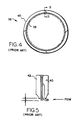
- a typical brush seal generally designated 36, includes a plurality of bristles 38 extending generally in a radial direction and which bristles 38 are disposed or sandwiched between a pair of seal plates 40 and 42.
- the bristles are generally formed of alloy steel wire drawn to a diameter of 0.002-0.006 inches, although larger-diameter wires for use in higher pressure environments may be used. From a review of Figure 5, it will be seen that the backing plate 42 prevents deflection of the bristles 38 under the loading from an upstream direction of the flow, while the distal ends of the bristle project from the distal edge of the plate 42 to engage the opposite component, e.g., the rotating shaft or wheel of a rotary machine.
- the bristles 38 are preferably welded between the plates 40 and 42. Additionally, it will be seen from a review of Figure 4 that the bristles and plates are provided in segments about the circumference of the axis of the rotating machine.
- the bristles project from the distal end of backing plate 42 a distance h which corresponds to the maximum deflection of the rotor in a radial direction. Consequently, the distance h must be a minimum corresponding to that maximum deflection and is dependent on the expected relative radial deflection for the specific machine and seal location. It may be on the order of 0.040 inches.
- the upstream plate 40 is useful for maintaining the bristles in place during seal fabrication, although plate 40 is not necessary to the seal when in use if axial space is at a premium.
- the bristles 38 extend along paths which are misaligned with the radius of the rotary machine. Thus, the bristles extend at an angle, preferably a common angle of approximately 45-60° to accommodate radial excursions of the shaft whereby the bristles may deflect without buckling.
- a combination labyrinth-brush seal For example, in Figure 6, the combination seal is illustrated with the brush seal lying at and along the axially upstream end of the sealing ring segment 16c with the teeth 22c of the labyrinth seal being located downstream of the brush seal 36c.
- the bristles 38c of the brush seal 36c are disposed between an upstream clamping plate 40c and an end wall of the sealing ring segment 16c.
- the bristles may be secured, for example, by welding.
- one of the labyrinth teeth 22c may be employed as the backing plate on the downstream side for the bristles 38c of the brush seal 36c.
- the fail-safe combination labyrinth-brush seal may be provided.
- the axial spacing is such that no axial increase in dimension is permitted, one or more of the labyrinth teeth 22c may be removed to accommodate securement of the brush seal 36c without increasing the axial dimension of the seal ring segment 16c.
- the downstream backing surface for the bristles 38c of the brush seal 36c may be tapered to provide anti-hysteresis qualities to the brush seal.
- the taper of the teeth of the labyrinth seal provides that anti-hysteresis quality when the existing teeth are employed as the backing plate for the additional seal.
- a low-friction coating material 44 such as boron nitrate, for example, may be provided on the upstream surface of the downstream backing plate or the upstream surface of the backing teeth of the labyrinth seal to reduce the friction force. This is illustrated in Figure 7, wherein a backing plate 42d for the brush seal 36d is provided with the low coefficient material 44.
- FIGs 8 and 9 illustrate different embodiments of the combination labyrinth-brush seal of the present invention.
- a brush seal 36e is provided on the upstream face of the sealing ring segment 16e using a tongue-and-groove fit between the backing plate 42e of the brush seal 36e and the upstream end face of the seal ring segment 16e.
- the brush seal 36e may be welded to the segment 16e or mechanical fasteners such as bolts may be used.
- the seal ring segment 16f may be provided with a central groove 46 along its inner face.
- the groove 46 may be machined in the labyrinth seal ring as original equipment or during retrofit.
- the seal ring for example, as illustrated in Figure 3, can then be disposed and secured, for example, by welding in the groove.
- the brush seal 36f lies generally intermediate the labyrinth seal teeth 22f of the combination labyrinth-brush seal.
- the embodiments illustrated in Figures 8 and 9 may be spring-backed for radial movement and be of the positive pressure variable clearance type, for example, as disclosed in U.S. Patent No. 5,002,288 of common assignee.
- the sealing ring segments may be of the type described in U.S. Patent No. 5,374,068, of common assignee herewith.
- the flow on the downstream bristle pack rather than being radially outwardly and tending to pull the bristle pack apart and damaging the seal, is radially inwardly along the upstream edge of the downstream bristle pack, thus preventing damage to the downstream bristle pack. This is particularly effective in gas turbines.
- bristle packs may be disposed along opposite axial ends of individual sealing ring segments or, as illustrated in Figure 13, the bristle packs 36j may be disposed in multi-stage sealing segments at either the ends of the segments or intermediate their axial extent as illustrated. It will be appreciated that the bristle packs with the labyrinth seal teeth may be provided as original equipment or as a retrofit using the tongue-and-groove arrangement illustrated in Figure 8 or the groove arrangement illustrated in Figure 9.
- the combination labyrinth-brush seal hereof may be employed at the tip of a rotating blade or bucket.
- the brush seal 36k may be applied to an axial end of a sealing strip 48 mounting labyrinth seal teeth 22k for sealing with the bucket cover 50 of bucket 52.
- the end mounting of the brush seal 36k can be replaced by a grooved mounting of the brush seal 36k intermediate axially adjacent teeth similarly as illustrated in Figure 9.
- the brush seal can be secured by welding or by mechanical means and can be provided as original equipment or as a retrofit.
- Figure 14 also illustrates a labyrinth seal tooth 221 adjacent the root of the turbine bucket or vane 52.
- This labyrinth tooth 221 forms a root radial spill strip seal 49.
- a brush seal as previously described, may be provided at this location within the rotary machine similarly as in the previous embodiments by mounting the brush seal in tandem with the labyrinth seal, providing the brush seal backing plate with a tapered profile or applying a low coefficient of friction material thereto or utilizing an existing labyrinth tooth as the backing plate.
- the rotating part can be particularly designed to mitigate wear on the brush seal.
- the shaft 10m may be provided with a groove 51 to decrease the interference.
- the brush seal 36m is illustrated in a cold position bearing against a rotor of a certain diameter at an axial location spaced from groove 51.
- the steady-state location of the brush seal is illustrated vis-a-vis the larger diameter portion of shaft 10m adjacent the rotor groove 51.
- the shutdown position of the rotor and brush seal is illustrated, with the brush seal tips engaging in the groove. It will be appreciated that this form of the invention can be used with or without the labyrinth seal teeth.
Landscapes
- Engineering & Computer Science (AREA)
- General Engineering & Computer Science (AREA)
- Mechanical Engineering (AREA)
- Turbine Rotor Nozzle Sealing (AREA)
- Sealing Using Fluids, Sealing Without Contact, And Removal Of Oil (AREA)
Claims (8)
- Verfahren zum Erzeugen einer Kombinations-Labyrinth- und Bürstendichtung zwischen einem Dichtungsband und Rotorschaufelabdeckungen in einer Rotationsmaschine mit einer mehrere drehbare Laufschaufeln (52) aufweisenden drehbaren Komponente (10) und einer das Dichtungsband (16c, 16e, 16f) aufweisenden bezüglich Rotation fixierten Komponente, wobei die Komponenten um eine gemeinsame Achse herum liegen, die Laufschaufeln (52) die Rotorschaufelabdeckungen (50) angrenzend an ihre radial äußeren Enden tragen, und eine Labyrinthdichtung (14) zwischen den Komponenten wenigstens einen sich im Wesentlichen um den Umfang herum ersteckenden durch das Dichtungsband (16c, 16e, 16f, 48) getragenen und im wesentlichen radial zu den Abmessungen 50 vorstehenden Zahn (22, 22c, 22f, 22i) enthält, um eine Dichtung dazwischen zu bewirken, wobei das Verfahren die Schritte der Anbringung einer Umfangsanordnung diskreter Bürsten (38c) auf den Band axial angrenzend an den wenigstens einen Zahn (22, 22c, 22f, 22i) durch Befestigen der Anordnung der diskreten Bürsten (38c) an dem Band (16c, 16e, 16f) aufweist, wobei die Bürsten (38c) in einer Ebene im Wesentlichen senkrecht zu der Achse liegen und wobei deren distalen Enden zu den Abdeckungen (50) über die radiale Erstreckung des wenigstens einen Zahnes (22, 22c, 22f, 22i) hinaus für eine im Wesentlichen abgedichteten Verbindung zu den Abdeckungen (50) vorstehen.
- Verfahren nach Anspruch 1, einschließlich des axialen Einbaus der Anordnung von Bürsten (38c) gegenüber einer Anstromseite des einen Zahnes (22, 22c, 22f, 22i).
- Verfahren nach Anspruch 1, einschließlich der Anbringung der Anordnung von Bürsten (38c) zwischen einem Paar von Unterstützungsplatten (42d, 42c) und in mehreren Lagen davon in einer axialen Richtung und der Befestigung der Platten (42d, 42c) an einer Endfläche des Bands (16c, 16e, 16f, 48).
- Verfahren nach Anspruch 1, wobei die Labyrinthdichtung (14) mehrere sich im Wesentlichen um den Umfang erstreckende axial in Abstand angeordnete Zähne (22, 22c, 22f, 22i), die durch das Band (16c, 16e, 16f, 48) getragen werden und radial zu den Abdeckungen (50) hin vorstehen, und das Anbringen der Anordnung von Bürsten (38c) in mehreren Schichten davon in einer axialen Richtung und auf dem Band (16c, 16e, 16f, 48) zwischen einem benachbarten Paar der Zähne (22, 22c, 22f, 22e) beinhaltet.
- Verfahren nach Anspruch 1, wobei die Labyrinthdichtung (14) mehrere sich im Wesentlichen um den Umfang erstreckende axial in Abstand angeordnete Zähne (22, 22c, 22f, 22i), die durch das Band (16c, 16e, 16f, 48) getragen werden und radial zu den Abdeckungen (50) hin vorstehen, und das Entfernen wenigstens eines Abschnittes eines der Zähne (22, 22c, 22f, 22i) und das Ersetzen des entfernten Zahnabschnittes durch die Anordnung von Bürsten (38c) beinhaltet.
- Verfahren nach Anspruch 1, wobei die Maschine aus einer Dampfturbine mit einem festen Gehäuse besteht, das Dichtungsband mehrere von dem festen Gehäuse getragene gekrümmte Segmente zur Bewegung in radialer Richtung auf die Achse zu und von dieser weg enthält, wenigstens eine Feder für jedes Segment das Segment zur Bewegung in einer von radialen Richtungen vorspannt, wenigstens ein Zahn (22, 22c, 22f, 22i) von einer gekrümmten Innenoberfläche Schrittes der Befestigung wenigstens eines gekrümmten Abschnittes der Anordnung von Bürsten (38c) an jedem Segment an einer axial in Abstand angeordneten Position entlang dem wenigstens einen Segment in Bezug auf die Zähne (22, 22c, 22f, 22i).
- Verfahren nach Anspruch 6, einschließlich der Ausbildung einer Nut (46) in einer Innenfläche jedes Segmentes, Anbringung eines gekrümmten Abschnittes der Anordnung von Bürsten (38c) zwischen einem Paar gekrümmter Platten (40, 42) und einer Befestigung der Bürsten (38c) und Platten (40, 42) in den Nuten (46) der Segmente.
- Verfahren nach Anspruch 6, einschließlich der Schritte der Befestigung einer ersten Anordnung gekrümmter Abschnitte der sich um den Umfang herum erstreckenden Anordnung von Bürsten (38c) an den Segmenten angrenzend an deren Seite stromauf von den Zähnen (22, 22c, 22f, 22i) und der Befestigung einer zweiten Anordnung gekrümmter Abschnitte der sich um den Umfang herum erstreckenden Anordnung von Bürsten (38c) an den Segmenten angrenzend an deren gegenüberliegenden Seite stromab von den Zähnen (22, 22c, 22f, 22i), wodurch die Zähne axial zwischen den ersten und zweiten Anordnung von Bürsten (38c) liegen.
Applications Claiming Priority (2)
| Application Number | Priority Date | Filing Date | Title |
|---|---|---|---|
| US67266596A | 1996-06-28 | 1996-06-28 | |
| US672665 | 1996-06-28 |
Publications (2)
| Publication Number | Publication Date |
|---|---|
| EP0816726A1 EP0816726A1 (de) | 1998-01-07 |
| EP0816726B1 true EP0816726B1 (de) | 2006-09-20 |
Family
ID=24699508
Family Applications (1)
| Application Number | Title | Priority Date | Filing Date |
|---|---|---|---|
| EP19970304685 Revoked EP0816726B1 (de) | 1996-06-28 | 1997-06-27 | Bürstendichtungen und kombinierte Labyrinth- und Bürstendichtungen für drehende Maschinen |
Country Status (3)
| Country | Link |
|---|---|
| EP (1) | EP0816726B1 (de) |
| CA (1) | CA2205877A1 (de) |
| DE (1) | DE69736690T2 (de) |
Cited By (2)
| Publication number | Priority date | Publication date | Assignee | Title |
|---|---|---|---|---|
| US8936247B2 (en) | 2010-05-18 | 2015-01-20 | General Electric Company | Seal assembly including plateau and concave portion in mating surface for seal tooth in turbine |
| US11293295B2 (en) | 2019-09-13 | 2022-04-05 | Pratt & Whitney Canada Corp. | Labyrinth seal with angled fins |
Families Citing this family (27)
| Publication number | Priority date | Publication date | Assignee | Title |
|---|---|---|---|---|
| EP0947667B1 (de) * | 1998-04-01 | 2004-12-15 | Mitsubishi Heavy Industries, Ltd. | Dichtungsanordnung für eine Gasturbine |
| US6220814B1 (en) | 1998-07-16 | 2001-04-24 | Siemens Westinghouse Power Corporation | Turbine interstage sealing arrangement |
| US6053699A (en) * | 1998-07-27 | 2000-04-25 | General Electric Company | Steam turbine having a brush seal assembly |
| US6030175A (en) * | 1998-09-23 | 2000-02-29 | General Electric Company | Hybrid seal and rotary machine containing such hybrid seal |
| WO2000047919A1 (en) * | 1999-02-09 | 2000-08-17 | General Electric Company | Combined labyrinth and brush seals for rotary machines |
| US6139019A (en) * | 1999-03-24 | 2000-10-31 | General Electric Company | Seal assembly and rotary machine containing such seal |
| US6261057B1 (en) * | 1999-10-04 | 2001-07-17 | General Electric Company | Arrangement and method for accurately radially locating a turbine brush seal |
| CA2372256C (en) * | 2000-04-06 | 2007-05-15 | Turbocare, Inc. | Improved brush-seal designs for turbines and similar rotary apparatus |
| JP2002139153A (ja) * | 2000-11-01 | 2002-05-17 | Eagle Engineering Aerospace Co Ltd | ブラシ型シール装置 |
| GB0201666D0 (en) * | 2002-01-25 | 2002-03-13 | Cross Mfg 1938 Company Ltd | A brush seal element |
| US6854735B2 (en) * | 2002-08-26 | 2005-02-15 | General Electric Company | In situ load sharing brush seals |
| DE10351583B4 (de) * | 2003-11-05 | 2020-10-22 | MTU Aero Engines AG | Dichtungsanordnung |
| CN101539032B (zh) * | 2008-03-18 | 2010-12-08 | 王胜五 | 铁素体自调边界汽封 |
| US9297277B2 (en) | 2011-09-30 | 2016-03-29 | General Electric Company | Power plant |
| US9587505B2 (en) | 2013-12-05 | 2017-03-07 | General Electric Company | L brush seal for turbomachinery application |
| US10041367B2 (en) | 2013-12-12 | 2018-08-07 | General Electric Company | Axially faced seal system |
| US9322287B2 (en) | 2014-06-03 | 2016-04-26 | General Electric Company | Brush seal for turbine |
| CN107401427A (zh) * | 2017-08-07 | 2017-11-28 | 昆明理工大学 | 一种可调接触间隙的低迟滞组合刷式密封 |
| CN107355540B (zh) * | 2017-08-18 | 2023-07-14 | 国网湖南省电力公司 | 间隙自适应调整密封结构 |
| CN108979740B (zh) * | 2018-09-04 | 2023-07-21 | 昆明理工大学 | 一种低磨损迷宫-刷式复合密封装置 |
| CN109458459A (zh) * | 2018-12-19 | 2019-03-12 | 北京中智渝桐节能设备有限公司 | 一种采用Ni基石墨复合材料的新型密封 |
| CN110017179B (zh) * | 2019-04-18 | 2024-01-02 | 沈阳航空航天大学 | 刷丝周向倾角可调的刷式密封结构 |
| CN110849802B (zh) * | 2019-11-18 | 2024-09-13 | 沈阳航空航天大学 | 刷式密封摩擦磨损特性实验测试装置 |
| CN111648831B (zh) * | 2020-05-20 | 2024-05-07 | 中国核动力研究设计院 | 一种超临界二氧化碳涡轮轴端密封失效保护装置及方法 |
| CN112196629B (zh) * | 2020-11-12 | 2022-06-24 | 东方电气集团东方汽轮机有限公司 | 一种汽轮机动叶片密封结构及密封方法 |
| CN116201898A (zh) * | 2023-04-28 | 2023-06-02 | 势加透博(成都)科技有限公司 | 刷式密封组件 |
| CN117027961B (zh) * | 2023-10-08 | 2023-12-01 | 中国航发燃气轮机有限公司 | 一种涡轮叶片 |
Family Cites Families (3)
| Publication number | Priority date | Publication date | Assignee | Title |
|---|---|---|---|---|
| FR2690493B1 (fr) * | 1992-04-23 | 1996-10-25 | Snecma | Joint annulaire a brosse. |
| GB2301635B (en) * | 1995-04-12 | 1998-09-16 | Gec Alsthom Ltd | Shaft seal arrangement |
| US5630590A (en) * | 1996-03-26 | 1997-05-20 | United Technologies Corporation | Method and apparatus for improving the airsealing effectiveness in a turbine engine |
-
1997
- 1997-05-22 CA CA002205877A patent/CA2205877A1/en not_active Abandoned
- 1997-06-27 EP EP19970304685 patent/EP0816726B1/de not_active Revoked
- 1997-06-27 DE DE1997636690 patent/DE69736690T2/de not_active Expired - Fee Related
Cited By (2)
| Publication number | Priority date | Publication date | Assignee | Title |
|---|---|---|---|---|
| US8936247B2 (en) | 2010-05-18 | 2015-01-20 | General Electric Company | Seal assembly including plateau and concave portion in mating surface for seal tooth in turbine |
| US11293295B2 (en) | 2019-09-13 | 2022-04-05 | Pratt & Whitney Canada Corp. | Labyrinth seal with angled fins |
Also Published As
| Publication number | Publication date |
|---|---|
| CA2205877A1 (en) | 1997-12-28 |
| DE69736690T2 (de) | 2007-09-06 |
| DE69736690D1 (de) | 2006-11-02 |
| EP0816726A1 (de) | 1998-01-07 |
Similar Documents
| Publication | Publication Date | Title |
|---|---|---|
| US6131910A (en) | Brush seals and combined labyrinth and brush seals for rotary machines | |
| EP0816726B1 (de) | Bürstendichtungen und kombinierte Labyrinth- und Bürstendichtungen für drehende Maschinen | |
| US6435513B2 (en) | Combined brush seal and labyrinth seal segment for rotary machines | |
| EP0911554B1 (de) | Kombinierte Bürsten/Labyrinth Dichtung für Rotationsmaschinen | |
| US6131911A (en) | Brush seals and combined labyrinth and brush seals for rotary machines | |
| US7857582B2 (en) | Abradable labyrinth tooth seal | |
| US6547522B2 (en) | Spring-backed abradable seal for turbomachinery | |
| EP2580498B1 (de) | Film mit einer druckbetätigten lamellendichtungsanordnung | |
| US7578509B2 (en) | Seal assembly and rotary machine containing such seal | |
| CN1800589B (zh) | 用于涡轮转动和静止部件之间的密封的可更换的磨耗密封支承件 | |
| EP0945654B1 (de) | Überdruckbetriebene Bürstendichtung | |
| US20020117806A1 (en) | Seal assembly and rotary machine containing such seal | |
| US20040126225A1 (en) | Rotary machine sealing assembly | |
| US9587505B2 (en) | L brush seal for turbomachinery application | |
| EP2233800B1 (de) | Dichtungselement, Anordnung und Verfahren | |
| EP1712743A2 (de) | Turbine mit einer abreibbaren Dichtung zwischen einem Rotor und einem stationären Bauteil | |
| EP2279364A1 (de) | Kontaktfreie abdichtung für einen gasturbinenmotor | |
| EP1387043B1 (de) | Abdichtungsvorrichtung für Dampfturbinenleitapparate | |
| EP1169586B1 (de) | Bürstendichtung zur verwendung in dampfturbine | |
| US20070040335A1 (en) | Axially adjustable sealing ring | |
| KR100659414B1 (ko) | 자동조심 브러시 시일을 포함하는 회전 기계 | |
| Stephen et al. | Development of brush seal technology for steam turbine retrofit applications |
Legal Events
| Date | Code | Title | Description |
|---|---|---|---|
| PUAI | Public reference made under article 153(3) epc to a published international application that has entered the european phase |
Free format text: ORIGINAL CODE: 0009012 |
|
| AK | Designated contracting states |
Kind code of ref document: A1 Designated state(s): CH DE FR GB IT LI |
|
| 17P | Request for examination filed |
Effective date: 19980707 |
|
| AKX | Designation fees paid |
Free format text: CH DE FR GB IT LI |
|
| RBV | Designated contracting states (corrected) |
Designated state(s): CH DE FR GB IT LI |
|
| 17Q | First examination report despatched |
Effective date: 20020527 |
|
| GRAP | Despatch of communication of intention to grant a patent |
Free format text: ORIGINAL CODE: EPIDOSNIGR1 |
|
| GRAS | Grant fee paid |
Free format text: ORIGINAL CODE: EPIDOSNIGR3 |
|
| GRAA | (expected) grant |
Free format text: ORIGINAL CODE: 0009210 |
|
| AK | Designated contracting states |
Kind code of ref document: B1 Designated state(s): CH DE FR GB IT LI |
|
| PG25 | Lapsed in a contracting state [announced via postgrant information from national office to epo] |
Ref country code: IT Free format text: LAPSE BECAUSE OF FAILURE TO SUBMIT A TRANSLATION OF THE DESCRIPTION OR TO PAY THE FEE WITHIN THE PRESCRIBED TIME-LIMIT;WARNING: LAPSES OF ITALIAN PATENTS WITH EFFECTIVE DATE BEFORE 2007 MAY HAVE OCCURRED AT ANY TIME BEFORE 2007. THE CORRECT EFFECTIVE DATE MAY BE DIFFERENT FROM THE ONE RECORDED. Effective date: 20060920 |
|
| REG | Reference to a national code |
Ref country code: GB Ref legal event code: FG4D |
|
| REG | Reference to a national code |
Ref country code: CH Ref legal event code: EP |
|
| REF | Corresponds to: |
Ref document number: 69736690 Country of ref document: DE Date of ref document: 20061102 Kind code of ref document: P |
|
| REG | Reference to a national code |
Ref country code: CH Ref legal event code: NV Representative=s name: SERVOPATENT GMBH |
|
| ET | Fr: translation filed | ||
| PLBI | Opposition filed |
Free format text: ORIGINAL CODE: 0009260 |
|
| 26 | Opposition filed |
Opponent name: ALSTOM TECHNOLOGY LTD Effective date: 20070620 |
|
| PLAX | Notice of opposition and request to file observation + time limit sent |
Free format text: ORIGINAL CODE: EPIDOSNOBS2 |
|
| PLAF | Information modified related to communication of a notice of opposition and request to file observations + time limit |
Free format text: ORIGINAL CODE: EPIDOSCOBS2 |
|
| PLAF | Information modified related to communication of a notice of opposition and request to file observations + time limit |
Free format text: ORIGINAL CODE: EPIDOSCOBS2 |
|
| PLBB | Reply of patent proprietor to notice(s) of opposition received |
Free format text: ORIGINAL CODE: EPIDOSNOBS3 |
|
| REG | Reference to a national code |
Ref country code: CH Ref legal event code: PFA Owner name: GENERAL ELECTRIC COMPANY Free format text: GENERAL ELECTRIC COMPANY#1 RIVER ROAD#SCHENECTADY, NY 12345 (US) -TRANSFER TO- GENERAL ELECTRIC COMPANY#1 RIVER ROAD#SCHENECTADY, NY 12345 (US) |
|
| PGFP | Annual fee paid to national office [announced via postgrant information from national office to epo] |
Ref country code: FR Payment date: 20090617 Year of fee payment: 13 |
|
| RDAF | Communication despatched that patent is revoked |
Free format text: ORIGINAL CODE: EPIDOSNREV1 |
|
| PGFP | Annual fee paid to national office [announced via postgrant information from national office to epo] |
Ref country code: CH Payment date: 20090625 Year of fee payment: 13 |
|
| PGFP | Annual fee paid to national office [announced via postgrant information from national office to epo] |
Ref country code: GB Payment date: 20090625 Year of fee payment: 13 Ref country code: DE Payment date: 20090629 Year of fee payment: 13 |
|
| APBM | Appeal reference recorded |
Free format text: ORIGINAL CODE: EPIDOSNREFNO |
|
| APBP | Date of receipt of notice of appeal recorded |
Free format text: ORIGINAL CODE: EPIDOSNNOA2O |
|
| APAH | Appeal reference modified |
Free format text: ORIGINAL CODE: EPIDOSCREFNO |
|
| PLAB | Opposition data, opponent's data or that of the opponent's representative modified |
Free format text: ORIGINAL CODE: 0009299OPPO |
|
| APBQ | Date of receipt of statement of grounds of appeal recorded |
Free format text: ORIGINAL CODE: EPIDOSNNOA3O |
|
| R26 | Opposition filed (corrected) |
Opponent name: ALSTOM TECHNOLOGY LTD Effective date: 20070620 |
|
| PGFP | Annual fee paid to national office [announced via postgrant information from national office to epo] |
Ref country code: IT Payment date: 20090627 Year of fee payment: 13 |
|
| REG | Reference to a national code |
Ref country code: CH Ref legal event code: PL |
|
| GBPC | Gb: european patent ceased through non-payment of renewal fee |
Effective date: 20100627 |
|
| REG | Reference to a national code |
Ref country code: FR Ref legal event code: ST Effective date: 20110228 |
|
| PG25 | Lapsed in a contracting state [announced via postgrant information from national office to epo] |
Ref country code: IT Free format text: LAPSE BECAUSE OF NON-PAYMENT OF DUE FEES Effective date: 20100627 |
|
| PG25 | Lapsed in a contracting state [announced via postgrant information from national office to epo] |
Ref country code: CH Free format text: LAPSE BECAUSE OF NON-PAYMENT OF DUE FEES Effective date: 20100630 Ref country code: DE Free format text: LAPSE BECAUSE OF NON-PAYMENT OF DUE FEES Effective date: 20110101 Ref country code: LI Free format text: LAPSE BECAUSE OF NON-PAYMENT OF DUE FEES Effective date: 20100630 |
|
| PG25 | Lapsed in a contracting state [announced via postgrant information from national office to epo] |
Ref country code: FR Free format text: LAPSE BECAUSE OF NON-PAYMENT OF DUE FEES Effective date: 20100630 |
|
| PG25 | Lapsed in a contracting state [announced via postgrant information from national office to epo] |
Ref country code: GB Free format text: LAPSE BECAUSE OF NON-PAYMENT OF DUE FEES Effective date: 20100627 |
|
| APBY | Invitation to file observations in appeal sent |
Free format text: ORIGINAL CODE: EPIDOSNOBA2O |
|
| APBY | Invitation to file observations in appeal sent |
Free format text: ORIGINAL CODE: EPIDOSNOBA2O |
|
| APBU | Appeal procedure closed |
Free format text: ORIGINAL CODE: EPIDOSNNOA9O |
|
| RDAG | Patent revoked |
Free format text: ORIGINAL CODE: 0009271 |
|
| STAA | Information on the status of an ep patent application or granted ep patent |
Free format text: STATUS: PATENT REVOKED |
|
| 27W | Patent revoked |
Effective date: 20111028 |