EP0816599B1 - Vorrichtung zur Fernsteuerung eines Garagentores - Google Patents
Vorrichtung zur Fernsteuerung eines Garagentores Download PDFInfo
- Publication number
- EP0816599B1 EP0816599B1 EP97107894A EP97107894A EP0816599B1 EP 0816599 B1 EP0816599 B1 EP 0816599B1 EP 97107894 A EP97107894 A EP 97107894A EP 97107894 A EP97107894 A EP 97107894A EP 0816599 B1 EP0816599 B1 EP 0816599B1
- Authority
- EP
- European Patent Office
- Prior art keywords
- transmitter
- receiver
- garage door
- oscillator
- signals
- Prior art date
- Legal status (The legal status is an assumption and is not a legal conclusion. Google has not performed a legal analysis and makes no representation as to the accuracy of the status listed.)
- Expired - Lifetime
Links
- 238000005096 rolling process Methods 0.000 claims description 8
- 238000000034 method Methods 0.000 claims description 7
- 230000002457 bidirectional effect Effects 0.000 claims description 4
- 230000001105 regulatory effect Effects 0.000 claims description 2
- 230000005540 biological transmission Effects 0.000 description 6
- 238000012790 confirmation Methods 0.000 description 6
- 230000006870 function Effects 0.000 description 5
- 238000004422 calculation algorithm Methods 0.000 description 2
- 238000010586 diagram Methods 0.000 description 2
- 230000036039 immunity Effects 0.000 description 2
- 230000008569 process Effects 0.000 description 2
- 238000012549 training Methods 0.000 description 2
- 229910000859 α-Fe Inorganic materials 0.000 description 2
- 230000009471 action Effects 0.000 description 1
- 230000008901 benefit Effects 0.000 description 1
- 230000008859 change Effects 0.000 description 1
- 238000011156 evaluation Methods 0.000 description 1
- 230000007257 malfunction Effects 0.000 description 1
- 238000005259 measurement Methods 0.000 description 1
Images




Classifications
-
- G—PHYSICS
- G08—SIGNALLING
- G08C—TRANSMISSION SYSTEMS FOR MEASURED VALUES, CONTROL OR SIMILAR SIGNALS
- G08C17/00—Arrangements for transmitting signals characterised by the use of a wireless electrical link
- G08C17/02—Arrangements for transmitting signals characterised by the use of a wireless electrical link using a radio link
-
- G—PHYSICS
- G07—CHECKING-DEVICES
- G07C—TIME OR ATTENDANCE REGISTERS; REGISTERING OR INDICATING THE WORKING OF MACHINES; GENERATING RANDOM NUMBERS; VOTING OR LOTTERY APPARATUS; ARRANGEMENTS, SYSTEMS OR APPARATUS FOR CHECKING NOT PROVIDED FOR ELSEWHERE
- G07C9/00—Individual registration on entry or exit
- G07C9/00174—Electronically operated locks; Circuits therefor; Nonmechanical keys therefor, e.g. passive or active electrical keys or other data carriers without mechanical keys
- G07C9/00309—Electronically operated locks; Circuits therefor; Nonmechanical keys therefor, e.g. passive or active electrical keys or other data carriers without mechanical keys operated with bidirectional data transmission between data carrier and locks
-
- G—PHYSICS
- G07—CHECKING-DEVICES
- G07C—TIME OR ATTENDANCE REGISTERS; REGISTERING OR INDICATING THE WORKING OF MACHINES; GENERATING RANDOM NUMBERS; VOTING OR LOTTERY APPARATUS; ARRANGEMENTS, SYSTEMS OR APPARATUS FOR CHECKING NOT PROVIDED FOR ELSEWHERE
- G07C9/00—Individual registration on entry or exit
- G07C9/00174—Electronically operated locks; Circuits therefor; Nonmechanical keys therefor, e.g. passive or active electrical keys or other data carriers without mechanical keys
- G07C9/00182—Electronically operated locks; Circuits therefor; Nonmechanical keys therefor, e.g. passive or active electrical keys or other data carriers without mechanical keys operated with unidirectional data transmission between data carrier and locks
- G07C2009/0023—Electronically operated locks; Circuits therefor; Nonmechanical keys therefor, e.g. passive or active electrical keys or other data carriers without mechanical keys operated with unidirectional data transmission between data carrier and locks with encription of the transmittted data signal
-
- G—PHYSICS
- G07—CHECKING-DEVICES
- G07C—TIME OR ATTENDANCE REGISTERS; REGISTERING OR INDICATING THE WORKING OF MACHINES; GENERATING RANDOM NUMBERS; VOTING OR LOTTERY APPARATUS; ARRANGEMENTS, SYSTEMS OR APPARATUS FOR CHECKING NOT PROVIDED FOR ELSEWHERE
- G07C9/00—Individual registration on entry or exit
- G07C9/00174—Electronically operated locks; Circuits therefor; Nonmechanical keys therefor, e.g. passive or active electrical keys or other data carriers without mechanical keys
- G07C9/00182—Electronically operated locks; Circuits therefor; Nonmechanical keys therefor, e.g. passive or active electrical keys or other data carriers without mechanical keys operated with unidirectional data transmission between data carrier and locks
- G07C2009/00238—Electronically operated locks; Circuits therefor; Nonmechanical keys therefor, e.g. passive or active electrical keys or other data carriers without mechanical keys operated with unidirectional data transmission between data carrier and locks the transmittted data signal containing a code which is changed
- G07C2009/00253—Electronically operated locks; Circuits therefor; Nonmechanical keys therefor, e.g. passive or active electrical keys or other data carriers without mechanical keys operated with unidirectional data transmission between data carrier and locks the transmittted data signal containing a code which is changed dynamically, e.g. variable code - rolling code
-
- G—PHYSICS
- G07—CHECKING-DEVICES
- G07C—TIME OR ATTENDANCE REGISTERS; REGISTERING OR INDICATING THE WORKING OF MACHINES; GENERATING RANDOM NUMBERS; VOTING OR LOTTERY APPARATUS; ARRANGEMENTS, SYSTEMS OR APPARATUS FOR CHECKING NOT PROVIDED FOR ELSEWHERE
- G07C9/00—Individual registration on entry or exit
- G07C9/00174—Electronically operated locks; Circuits therefor; Nonmechanical keys therefor, e.g. passive or active electrical keys or other data carriers without mechanical keys
- G07C9/00309—Electronically operated locks; Circuits therefor; Nonmechanical keys therefor, e.g. passive or active electrical keys or other data carriers without mechanical keys operated with bidirectional data transmission between data carrier and locks
- G07C2009/00412—Electronically operated locks; Circuits therefor; Nonmechanical keys therefor, e.g. passive or active electrical keys or other data carriers without mechanical keys operated with bidirectional data transmission between data carrier and locks the transmitted data signal being encrypted
-
- G—PHYSICS
- G07—CHECKING-DEVICES
- G07C—TIME OR ATTENDANCE REGISTERS; REGISTERING OR INDICATING THE WORKING OF MACHINES; GENERATING RANDOM NUMBERS; VOTING OR LOTTERY APPARATUS; ARRANGEMENTS, SYSTEMS OR APPARATUS FOR CHECKING NOT PROVIDED FOR ELSEWHERE
- G07C9/00—Individual registration on entry or exit
- G07C9/00174—Electronically operated locks; Circuits therefor; Nonmechanical keys therefor, e.g. passive or active electrical keys or other data carriers without mechanical keys
- G07C9/00309—Electronically operated locks; Circuits therefor; Nonmechanical keys therefor, e.g. passive or active electrical keys or other data carriers without mechanical keys operated with bidirectional data transmission between data carrier and locks
- G07C2009/0042—Electronically operated locks; Circuits therefor; Nonmechanical keys therefor, e.g. passive or active electrical keys or other data carriers without mechanical keys operated with bidirectional data transmission between data carrier and locks the transmitted data signal containing a code which is changed
- G07C2009/00476—Electronically operated locks; Circuits therefor; Nonmechanical keys therefor, e.g. passive or active electrical keys or other data carriers without mechanical keys operated with bidirectional data transmission between data carrier and locks the transmitted data signal containing a code which is changed dynamically
- G07C2009/00492—Electronically operated locks; Circuits therefor; Nonmechanical keys therefor, e.g. passive or active electrical keys or other data carriers without mechanical keys operated with bidirectional data transmission between data carrier and locks the transmitted data signal containing a code which is changed dynamically whereby the code is a rolling code
-
- G—PHYSICS
- G07—CHECKING-DEVICES
- G07C—TIME OR ATTENDANCE REGISTERS; REGISTERING OR INDICATING THE WORKING OF MACHINES; GENERATING RANDOM NUMBERS; VOTING OR LOTTERY APPARATUS; ARRANGEMENTS, SYSTEMS OR APPARATUS FOR CHECKING NOT PROVIDED FOR ELSEWHERE
- G07C9/00—Individual registration on entry or exit
- G07C9/00174—Electronically operated locks; Circuits therefor; Nonmechanical keys therefor, e.g. passive or active electrical keys or other data carriers without mechanical keys
- G07C2009/00753—Electronically operated locks; Circuits therefor; Nonmechanical keys therefor, e.g. passive or active electrical keys or other data carriers without mechanical keys operated by active electrical keys
- G07C2009/00769—Electronically operated locks; Circuits therefor; Nonmechanical keys therefor, e.g. passive or active electrical keys or other data carriers without mechanical keys operated by active electrical keys with data transmission performed by wireless means
- G07C2009/00793—Electronically operated locks; Circuits therefor; Nonmechanical keys therefor, e.g. passive or active electrical keys or other data carriers without mechanical keys operated by active electrical keys with data transmission performed by wireless means by Hertzian waves
-
- G—PHYSICS
- G07—CHECKING-DEVICES
- G07C—TIME OR ATTENDANCE REGISTERS; REGISTERING OR INDICATING THE WORKING OF MACHINES; GENERATING RANDOM NUMBERS; VOTING OR LOTTERY APPARATUS; ARRANGEMENTS, SYSTEMS OR APPARATUS FOR CHECKING NOT PROVIDED FOR ELSEWHERE
- G07C9/00—Individual registration on entry or exit
- G07C9/00174—Electronically operated locks; Circuits therefor; Nonmechanical keys therefor, e.g. passive or active electrical keys or other data carriers without mechanical keys
- G07C9/00658—Electronically operated locks; Circuits therefor; Nonmechanical keys therefor, e.g. passive or active electrical keys or other data carriers without mechanical keys operated by passive electrical keys
- G07C9/00714—Electronically operated locks; Circuits therefor; Nonmechanical keys therefor, e.g. passive or active electrical keys or other data carriers without mechanical keys operated by passive electrical keys with passive electrical components, e.g. resistor, capacitor, inductor
Definitions
- the invention relates to a device for remote control of a garage door according to the preamble of claim 1.
- the invention is based, the generic device the task to train so that with simple and reliable training remote opening of the garage door by unauthorized persons not possible.
- the transmitter signals encrypted using a rolling code using the RSA method. This ensures that the remote control signals do not have to be deciphered, even if the calculation algorithm used is known. This prevents unauthorized parties from leaving intercepted remote control signals the opening code for the garage door can decipher.
- the antenna signal of the transmitter or Receiver is mixed with the oscillator frequency.
- the antenna of the transmitter or the receiver as well as the oscillator are connected to the Mixing element connected. In it the antenna reception frequency mixed with the frequency of the oscillator.
- the output signal of the mixing element is fed to the filter, which is the difference frequency sieves from reception and oscillator frequency.
- the output signal of the filter is evaluated in the microprocessor and used for Control of the switch of the receiver used. He can can be connected to existing garage door controls.
- the receiver thus forms an adapter with the existing one Garage door drives subsequently with the invention Device can be equipped. Further advantageous features of the invention result from the others Claims, the description and the drawings.
- the device is used to remove a garage door 1 from a Motor vehicle 2 to open or close remotely conclude.
- the device is designed so that it connected to existing garage door controls can be. This makes it possible to do it later to assemble the device.
- the device consists of two devices.
- the first The device is a vehicle-side transmitter 3 (FIG. 2), preferably in the inside mirror of the motor vehicle 2 is housed.
- the transmitter 3 can also in the exterior rearview mirror of the motor vehicle or within the Vehicle should be provided at a suitable location. It is of course also possible to use the transmitter 3 Training handheld device.
- the second device is a receiver 4 (Fig. 1 and 3), in the garage 5 at more suitable Place is arranged.
- the receiver 4 is with a drive 6 (Fig. 1) of the garage door 1 connected.
- Remote control signals are transmitted with the transmitter 3, which are received and evaluated by the receiver 4.
- Fig. 2 the operation of the transmitter 3 is schematic shown.
- the transmitter 3 calculates before everyone Transmission the message to be transmitted from a unique Number of the sender (device identifier), a pressed one Key and a consecutive number of the Transmission as well as the coding key RSA. From these the encrypted message is divided into four parts formed, which is sent to the receiver 4.
- the receiver 4 evaluates the consecutive number of the transmission (meter reading) and checks them for a valid value. there the current counter reading must always be greater than the last encryption key used. The overflow the counter is intercepted.
- Due to the rolling code used in the RSA process is an excellent encryption, secure against eavesdropping of the signals to be transmitted guaranteed.
- Fig. 4 shows schematically a bidirectional connection between the vehicle-side transmitter 3 and the garage-side Receiver 4. In this case, a mutual exchange of messages between senders 3 and receiver 4. For this reason the transmitter is 3 also provided with a receiving device.
- First is encrypted from the vehicle-side transmitter 3 Message 7 to the receiver 4 on the garage side sent.
- This message is, for example, like Fig. 5a shows a 32-bit signal that i.a. the device identifier, identifying the key identifier and the rolling code Contains bits.
- This 32 bit signal is received by the receiver 4 recorded and evaluated. He then sends one too encrypted signal 8 back to transmitter 3. It is for example a 32 bit signal (Fig.
- This signal 8 is in turn evaluated by the transmitter 3.
- the transmitter 3 then sends a corresponding encrypted confirmation signal 9 to the receiver 4 back.
- This confirmation signal 9 can in turn be a 32nd Be bit signal (Fig. 5c), the bits for the device identifier of the transmitter 3, for the key identifier and a contains specified bit sequence.
- This specified bit sequence could be a rolling code, for example, to which an additional value is added.
- This encrypted confirmation signal 9 is sent by the receiver 4 evaluated, which is then a corresponding encrypted Sends confirmation signal 10 to the transmitter 3.
- This confirmation signal can in turn be a 32 bit signal, the bits for the device identification of the Receiver 4, control bits and a fixed one Can contain bit sequence.
- This confirmation signal 10 is evaluated by transmitter 3. It then sends a final report 11 back to the receiver 4. It contains how Fig. 5d shows an example of bits for the device identifier of transmitter 3, for the key identifier and for the device identifier of the recipient 4. Only when this final protocol 11 received and evaluated by the receiver 4 is, it gives the appropriate signals to the controller the garage door operator 6.
- transmitter 3 and receiver 4 ensures a high level of security against unauthorized persons Opening the garage door.
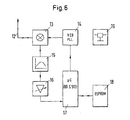
- the transmitter 3 has an antenna 12, preferably a ferrite antenna with which the corresponding Signals are sent to the receiver 4.
- the antenna 12 can also be bidirectional receive the signals coming from the receiver 4.
- the antenna signal is fed to a mixer 13, which also Signals from an oscillator 14, preferably a voltage-controlled one Oscillator (VCO) receives.
- the receiving frequency the antenna 12 and the oscillator frequency mixed in the mixer 13 and the difference frequency in one downstream baseband filter 15 sieved.
- the Signal of the baseband filter 15 is in a subsequent one Baseband amplifier 16, which is preferably regulated is amplified to a defined value.
- the output signal the baseband amplifier 16 becomes a microprocessor 17 fed to the oscillator 14 step by step votes on the receiving bands.
- the oscillator 14 is Part of a phase locked loop PLL in which the instantaneous phase of the voltage controlled oscillator 14 the current phase of the coming from the microprocessor 17 Input signals is tracked.
- an EEPROM 18 to be controlled in series is connected to the microprocessor 17. The measured values are stored in it and also retrieved from the microprocessor 17 if necessary.
- the transmitter 3 is also provided with a voltage regulator 19 provided to the voltage source of the motor vehicle 2 is connected. If the transmitter 3 is a handheld transmitter, it becomes independent of the current / voltage source of the Motor vehicle operated with batteries or rechargeable batteries.
- the Mixer 13, the baseband filter 15 and the baseband amplifier 16 are advantageously a component.
- the receiver 4 (Fig. 7) has a similar structure as the transmitter 3.
- the receiver 4 has an antenna 20 provided, which is advantageously a wire antenna. she catches the signals emitted by transmitter 3. Moreover are over it with bidirectional connection between Transmitter and receiver corresponding signals from the Receiver 4 emitted.
- the antenna 20 is with a Mixer 21 provided in which the antenna reception frequency is mixed with the frequency of an oscillator 22 which advantageously a voltage controlled oscillator (VCO) is.
- VCO voltage controlled oscillator
- the difference frequency from reception and oscillator frequency is in a downstream baseband filter 23 screened.
- the baseband filter 23 is preferably a controllable one Baseband amplifier 24 downstream of the signal amplified to a defined peak before it a microprocessor 25 is supplied.
- the signals supplied to the microprocessor 25 evaluated and the measurement results stored in an EEPROM 26, from which the microprocessor the appropriate Can also retrieve values.
- the oscillator 22 is in turn via the reception bands Voted.
- the oscillator 22 is part of one Phase locked loop PLL, in which the instantaneous phase of the oscillator 22 on the current phase of the microprocessor 35 incoming input signals is tracked. How at transmitter 3, the oscillator 22 and the phase locked loop are used PLL for frequency generation.
- the EEPROM 26 is advantageously controllable in series.
- the mixer 21, the baseband filter 23 and the baseband amplifier 24 advantageously a component.
- a voltage regulator is used to supply the voltage to the receiver 4 27 provided.
- a control relay 28 is connected to the microprocessor 25, that of the microprocessor 25 via a transistor T is controlled. With the control relay 28 be advantageously controlled three outputs of the receiver 4. Using these three outputs, different functions controlled. The outputs are NC contacts or capper provided. One of the exits should Can switch 220 V at 10 A. If necessary, too Overload protection can be provided to prevent overload of the receiver 4 and possibly the control of the garage door operator 6 to avoid.
- the outputs of the receiver 4 can additional one have programmable time function.
- This time function could, for example, be designed so that the recipient 4 can only be activated at certain times of the day, received no signals during the rest of the time can, or that with opening the garage door 1 lamps be switched on.
- the 40 MHz band is advantageously used as the carrier frequency.
- the intended phase locked loop PLL of the transmitter 3 and the receiver 4 leaves frequencies between 20 MHz and 60 MHz too.
- the type of modulation is advantageous Amplitude modulation used. To a high noise immunity to ensure is preferably a Negative modulation used.
- the transmitter 3 is advantageous with appropriate equipped with three function keys that the three outputs of the receiver 4 can be assigned.
- This Assignment is advantageously freely selectable, so that this Function buttons of transmitter 3 the corresponding outputs of the garage-side receiver 4 can be controlled can.
- the transmitter 3 advantageously has a basic setting, which is only required by the user of the transmitter 3 is changed.
- the transmitter 3 is advantageously designed so that it, for example with regard to its identifier with a from User freely selectable number can be labeled. This also makes it possible, for example, to use this identification number change if necessary. This is an advantage if the transmitter 3 is designed as a hand transmitter and has been lost. In this case, with a new hand-held transmitter, the device ID number is reset become.
- the receiver 4 can be advantageous with a learning mode be equipped. With a button or the like the microprocessor 25 is put into a learning mode, in which, for example, the identifier of a new handheld transmitter stores.
- the microprocessor 25 can also operate in a lock mode become. The microprocessor then deletes the corresponding one Transmitter 3 that is operated. It can also the total memory can be deleted. Then if this or another transmitter started up again to be switched, the receiver 4 in the learning mode to save the identifier of the transmitter.
- Fig. 8 shows this using the example of three hand transmitters HS1 to HS3. Become for example, two hand transmitters operated at the same time, the receiver 4 reacts due to the different Repetition rates are not. Then becomes just a handheld transmitter actuated, the receiver 4 reacts at the next Signal.
- the transmission process is preferably shorter than 1 ms.
- the processor 25 searches in the given Frequency ranges according to the transmitter signals and it works almost in parallel.
- the receiver 4 can be connected to existing garage door controls be connected. In this case it is the control relay 28 to the existing garage door drive 6 connected as an external switch. Such connectivity are available with every garage door operator, since the garage door 1 either via a button or a key switch is operated.
- the receiver 4 can be made very compact. Since the frequencies in Megahertz range, the device works on long distances, for example up to 60 m, perfectly.
Landscapes
- Engineering & Computer Science (AREA)
- Computer Networks & Wireless Communication (AREA)
- Physics & Mathematics (AREA)
- General Physics & Mathematics (AREA)
- Power-Operated Mechanisms For Wings (AREA)
- Lock And Its Accessories (AREA)
Description
- Fig. 1
- in schematischer Darstellung ein Fahrzeug vor einem Garagentor, das mittels einer erfindungsgemäßen Vorrichtung geöffnet bzw. geschlossen werden kann,
- Fig. 2
- in einer Prinzipdarstellung die Wirkungsweise eines kraftfahrzeugseitigen Senders der erfindungsgemäßen Vorrichtung,
- Fig. 3
- in einer Prinzipdarstellung die Wirkungsweise eines garagentorseitigen Empfängers der erfindungsgemäßen Vorrichtung,
- Fig. 4
- in einer Darstellung entsprechend Fig. 1 eine zweite Ausführungsform einer erfindungsgemäßen Vorrichtung,
- Fig. 5
- Sende- und Empfangsdaten der Vorrichtung gemäß Fig. 4,
- Fig. 6
- ein Blockschaltbild des kraftfahrzeugseitigen Senders der erfindungsgemäßen Vorrichtung,
- Fig. 7
- ein Blockschaltbild des garagentorseitigen Empfängers der erfindungsgemäßen Vorrichtung,
- Fig. 8
- die von verschiedenen Sendern abgegebenen Signale.
Claims (9)
- Vorrichtung zur Fernsteuerung eines Garagentores (1), mit mindestens einem Sender (3), der Signale aussendet, die durch Anwendung eines RSA-Verfahrens verschlüsselt sind, und mit wenigstens einem garagentorseitigen Empfänger (4), der einen Antrieb (6) des Garagentores (1) steuert, Fernsteuersignale vom Sender (3) erhält und mit einem Schalter (28) versehen ist, der an den Garagentorantrieb (6) angeschlossen ist,
dadurch gekennzeichnet, daß die vom Sender (3) ausgehenden Signale durch Anwendung des RSA-Verfahrens mit einem Rolling-Code verschlüsselt sind, daß das Antennensignal des Senders (3) bzw. des Empfängers (4) mit einer Osziallatorfrequenz gemischt wird, daß eine Antenne (12, 20) des Senders (3) bzw. des Empfängers (4) und ein Oszillator (14, 22) an ein Mischglied (13, 21) angeschlossen sind, dessen Ausgangssignal einem Filter (15, 23) zugeführt wird, der die Differenzfrequenz aus Antennensignal und Oszillatorfrequenz aussiebt, und daß das Ausgangssignal des Filters (15, 23) über einen Verstärker (16, 24) einem Mikroprozessor (17, 25) zugeführt wird, an den der Schalter (28) angeschlossen ist. - Vorrichtung nach Anspruch 1,
dadurch gekennzeichnet, daß die Verbindung zwischen Sender (3) und Empfänger (4) unidirektional ist. - Vorrichtung nach Anspruch 1,
dadurch gekennzeichnet, daß die Verbindung zwischen Sender (3) und Empfänger (4) bidirektional ist. - Vorrichtung nach einem der Ansprüche 1 bis 3,
dadurch gekennzeichnet, daß der Oszillator (14, 22) spannungsgeregelt ist. - Vorrichtung nach einem der Ansprüche 1 bis 4,
dadurch gekennzeichnet, daß der Oszillator (14, 22) Teil eines Phasenregelkreises (PLL) ist. - Vorrichtung nach Anspruch 5,
dadurch gekennzeichnet, daß das Ausgangssignal des Mikroprozessors (17, 25) dem Phasenregelkreis (PLL) zugeführt wird. - Vorrichtung nach einem der Ansprüche 1 bis 6,
dadurch gekennzeichnet, daß an den Mikroprozessor (17, 25) ein Speicher (18, 26), vorzugsweise ein EEPROM, angeschlossen ist. - Vorrichtung nach einem der Ansprüche 1 bis 7,
dadurch gekennzeichnet, daß der Schalter (28) ein Relais ist. - Vorrichtung nach einem der Ansprüche 5 bis 8,
dadurch gekennzeichnet, daß der Phasenregelkreis (PLL) eine Frequenzbereich zwischen etwa 20 MHz und etwa 60 MHz umfaßt.
Applications Claiming Priority (2)
| Application Number | Priority Date | Filing Date | Title |
|---|---|---|---|
| DE19625998 | 1996-06-28 | ||
| DE19625998A DE19625998A1 (de) | 1996-06-28 | 1996-06-28 | Vorrichtung zur Fernsteuerung eines Garagentores |
Publications (3)
| Publication Number | Publication Date |
|---|---|
| EP0816599A2 EP0816599A2 (de) | 1998-01-07 |
| EP0816599A3 EP0816599A3 (de) | 2000-09-06 |
| EP0816599B1 true EP0816599B1 (de) | 2004-01-28 |
Family
ID=7798332
Family Applications (1)
| Application Number | Title | Priority Date | Filing Date |
|---|---|---|---|
| EP97107894A Expired - Lifetime EP0816599B1 (de) | 1996-06-28 | 1997-05-15 | Vorrichtung zur Fernsteuerung eines Garagentores |
Country Status (2)
| Country | Link |
|---|---|
| EP (1) | EP0816599B1 (de) |
| DE (2) | DE19625998A1 (de) |
Families Citing this family (5)
| Publication number | Priority date | Publication date | Assignee | Title |
|---|---|---|---|---|
| AU3262299A (en) * | 1998-03-02 | 1999-09-20 | Konisa Limited | Identification system |
| DE19916847C2 (de) | 1999-04-14 | 2001-08-30 | Volkswagen Ag | Elektronische Steuervorrichtung in einem Kraftfahrzeug für mindestens einen elektromotorischen Antrieb, insbesondere Garagentoröffner |
| DE19934016C2 (de) * | 1999-07-20 | 2002-01-03 | Digades Gmbh | Funkfernbedienung |
| DE19952197C2 (de) | 1999-10-29 | 2002-01-31 | Siemens Ag | Takt- und Datenregenerator für unterschiedliche Datenraten |
| DE102015222930B4 (de) * | 2015-11-20 | 2024-05-29 | Robert Bosch Gmbh | Verfahren und Vorrichtung zum Absichern einer Bewegung eines Kraftfahrzeugs auf einer schrägen Rampe |
Family Cites Families (6)
| Publication number | Priority date | Publication date | Assignee | Title |
|---|---|---|---|---|
| DE3741324A1 (de) * | 1987-12-05 | 1989-06-15 | Alltronik Gmbh | Handsender zur aussendung codierter elektromagnetischer impulse und darauf abgestimmter empfaenger |
| US4942393A (en) * | 1988-05-27 | 1990-07-17 | Lectron Products, Inc. | Passive keyless entry system |
| US5144667A (en) * | 1990-12-20 | 1992-09-01 | Delco Electronics Corporation | Method of secure remote access |
| US5473318A (en) * | 1992-01-10 | 1995-12-05 | Active Control Technology Inc. | Secure remote control system with receiver controlled to add and delete identity codes |
| US5471668A (en) * | 1994-06-15 | 1995-11-28 | Texas Instruments Incorporated | Combined transmitter/receiver integrated circuit with learn mode |
| JP3319230B2 (ja) * | 1994-08-05 | 2002-08-26 | 株式会社デンソー | 遠隔操作装置 |
-
1996
- 1996-06-28 DE DE19625998A patent/DE19625998A1/de not_active Withdrawn
-
1997
- 1997-05-15 DE DE59711249T patent/DE59711249D1/de not_active Expired - Fee Related
- 1997-05-15 EP EP97107894A patent/EP0816599B1/de not_active Expired - Lifetime
Also Published As
| Publication number | Publication date |
|---|---|
| DE19625998A1 (de) | 1998-01-02 |
| EP0816599A3 (de) | 2000-09-06 |
| EP0816599A2 (de) | 1998-01-07 |
| DE59711249D1 (de) | 2004-03-04 |
Similar Documents
| Publication | Publication Date | Title |
|---|---|---|
| DE19624817B4 (de) | Ausrichtbarer Sendeempfänger zum Erlernen veränderlicher Kodierungen | |
| EP0958161B1 (de) | Codesignalgeber, insbesondere für ein diebstahlschutzsystem eines kraftfahrzeugs | |
| DE69325546T2 (de) | Passives schlüsselloses Eingangssystem | |
| DE4438276B4 (de) | Verfahren zum Betreiben einer Türver- und -entriegelung | |
| DE69914312T2 (de) | Mehrfrequenz programmiebarer sender | |
| DE19607017C2 (de) | Fernbedienungseinrichtung und Betriebsverfahren hierfür, insbesondere zur Ansteuerung von kraftfahrzeugbezogenen Einrichtungen | |
| DE19610116C2 (de) | Diebstahlschutzsystem für ein Kraftfahrzeug | |
| DE102004035506A1 (de) | Programmierbare Geräte-Fernbedienung | |
| DE19619694A1 (de) | Lernfähiger Sendeempfänger | |
| DE69910943T2 (de) | System zum Sichern einer bidirektionellen Datenübertragung für den Zugang zu einem abgeschlossenen Raum, insbesondere für den Zugang zu einem Fahrzeug | |
| WO2003102878A1 (de) | Nutzungsberechtigungskontrollverfahren | |
| DE102012216604A1 (de) | Systeme, Schaltungen und Verfahren für einseitige Datenübertragung auf Zeitstempelbasis | |
| EP1041224A2 (de) | Vorrichtung und Verfahren zur Freigabe einer Sicherungseinrichtung, insbesondere einer Zugangseinrichtung für ein Kraftfahrzeug | |
| DE69309605T2 (de) | Rundfunkempfangsgerät für ein Kraftfahrzeug mit einem abnehmbaren Bauteil welches wesentliche Funktionen des Geräts enthält | |
| DE69322520T2 (de) | Auf abstand steuerbares hochsicherheits-fahrzeugzugangssystem | |
| WO2002023948A1 (de) | Verfahren zur steuerung eines übertragungssystems, anwendung des verfahrens, ein übertragungssystem, eine empfangseinheit und ein hörgerät | |
| DE60102616T2 (de) | Handfreies Zugangs- und/oder Startsystem für Kraftfahrzeuge | |
| DE4433499C2 (de) | Elektronisches Diebstahlschutzsystem für ein Kraftfahrzeug | |
| DE19732157A1 (de) | Mehrfachfrequenzsender | |
| EP0816599A2 (de) | Vorrichtung zur Fernsteuerung eines Garagentores | |
| DE69721066T2 (de) | Automatische resynchronisation für fernbedienbare schlüssellose eingangsysteme | |
| EP1277632B1 (de) | Verfahren zum fernbedienten Ver- und/oder Entriegeln eines Fahrzeuges | |
| DE60113762T2 (de) | Handfreies Zugangssystem für Kraftfahrzeuge | |
| DE19603653B4 (de) | Sendestufe, insbesondere für ein fernbedienbares Diebstahlschutzsystem eines Kraftfahrzeugs | |
| DE10202802B4 (de) | Datenübertragungssystem |
Legal Events
| Date | Code | Title | Description |
|---|---|---|---|
| PUAI | Public reference made under article 153(3) epc to a published international application that has entered the european phase |
Free format text: ORIGINAL CODE: 0009012 |
|
| AK | Designated contracting states |
Kind code of ref document: A2 Designated state(s): BE DE ES FR GB IT LU |
|
| PUAL | Search report despatched |
Free format text: ORIGINAL CODE: 0009013 |
|
| AK | Designated contracting states |
Kind code of ref document: A3 Designated state(s): BE DE ES FR GB IT LU |
|
| 17P | Request for examination filed |
Effective date: 20001219 |
|
| 17Q | First examination report despatched |
Effective date: 20021213 |
|
| GRAP | Despatch of communication of intention to grant a patent |
Free format text: ORIGINAL CODE: EPIDOSNIGR1 |
|
| GRAS | Grant fee paid |
Free format text: ORIGINAL CODE: EPIDOSNIGR3 |
|
| RAP1 | Party data changed (applicant data changed or rights of an application transferred) |
Owner name: SCHEFENACKER VISION SYSTEMS GERMANY GMBH & CO. |
|
| GRAA | (expected) grant |
Free format text: ORIGINAL CODE: 0009210 |
|
| AK | Designated contracting states |
Kind code of ref document: B1 Designated state(s): BE DE ES FR GB IT LU |
|
| PG25 | Lapsed in a contracting state [announced via postgrant information from national office to epo] |
Ref country code: IT Free format text: LAPSE BECAUSE OF FAILURE TO SUBMIT A TRANSLATION OF THE DESCRIPTION OR TO PAY THE FEE WITHIN THE PRESCRIBED TIME-LIMIT;WARNING: LAPSES OF ITALIAN PATENTS WITH EFFECTIVE DATE BEFORE 2007 MAY HAVE OCCURRED AT ANY TIME BEFORE 2007. THE CORRECT EFFECTIVE DATE MAY BE DIFFERENT FROM THE ONE RECORDED. Effective date: 20040128 |
|
| REG | Reference to a national code |
Ref country code: GB Ref legal event code: FG4D Free format text: NOT ENGLISH |
|
| REF | Corresponds to: |
Ref document number: 59711249 Country of ref document: DE Date of ref document: 20040304 Kind code of ref document: P |
|
| PG25 | Lapsed in a contracting state [announced via postgrant information from national office to epo] |
Ref country code: ES Free format text: LAPSE BECAUSE OF FAILURE TO SUBMIT A TRANSLATION OF THE DESCRIPTION OR TO PAY THE FEE WITHIN THE PRESCRIBED TIME-LIMIT Effective date: 20040509 |
|
| GBT | Gb: translation of ep patent filed (gb section 77(6)(a)/1977) |
Effective date: 20040416 |
|
| PG25 | Lapsed in a contracting state [announced via postgrant information from national office to epo] |
Ref country code: LU Free format text: LAPSE BECAUSE OF NON-PAYMENT OF DUE FEES Effective date: 20040515 |
|
| PG25 | Lapsed in a contracting state [announced via postgrant information from national office to epo] |
Ref country code: BE Free format text: LAPSE BECAUSE OF NON-PAYMENT OF DUE FEES Effective date: 20040531 |
|
| ET | Fr: translation filed | ||
| BERE | Be: lapsed |
Owner name: *SCHEFENACKER VISION SYSTEMS GERMANY G.M.B.H. & CO Effective date: 20040531 |
|
| PLBE | No opposition filed within time limit |
Free format text: ORIGINAL CODE: 0009261 |
|
| STAA | Information on the status of an ep patent application or granted ep patent |
Free format text: STATUS: NO OPPOSITION FILED WITHIN TIME LIMIT |
|
| 26N | No opposition filed |
Effective date: 20041029 |
|
| PGFP | Annual fee paid to national office [announced via postgrant information from national office to epo] |
Ref country code: FR Payment date: 20050517 Year of fee payment: 9 |
|
| PGFP | Annual fee paid to national office [announced via postgrant information from national office to epo] |
Ref country code: GB Payment date: 20060406 Year of fee payment: 10 |
|
| PGFP | Annual fee paid to national office [announced via postgrant information from national office to epo] |
Ref country code: DE Payment date: 20060531 Year of fee payment: 10 |
|
| GBPC | Gb: european patent ceased through non-payment of renewal fee |
Effective date: 20070515 |
|
| REG | Reference to a national code |
Ref country code: FR Ref legal event code: ST Effective date: 20080131 |
|
| PG25 | Lapsed in a contracting state [announced via postgrant information from national office to epo] |
Ref country code: DE Free format text: LAPSE BECAUSE OF NON-PAYMENT OF DUE FEES Effective date: 20071201 |
|
| PG25 | Lapsed in a contracting state [announced via postgrant information from national office to epo] |
Ref country code: GB Free format text: LAPSE BECAUSE OF NON-PAYMENT OF DUE FEES Effective date: 20070515 |
|
| PG25 | Lapsed in a contracting state [announced via postgrant information from national office to epo] |
Ref country code: FR Free format text: LAPSE BECAUSE OF NON-PAYMENT OF DUE FEES Effective date: 20070531 |
|
| PG25 | Lapsed in a contracting state [announced via postgrant information from national office to epo] |
Ref country code: FR Free format text: LAPSE BECAUSE OF NON-PAYMENT OF DUE FEES Effective date: 20060531 |