EP0815999B1 - Method & control system for applying solder flux to a printed circuit - Google Patents
Method & control system for applying solder flux to a printed circuit Download PDFInfo
- Publication number
- EP0815999B1 EP0815999B1 EP97304323A EP97304323A EP0815999B1 EP 0815999 B1 EP0815999 B1 EP 0815999B1 EP 97304323 A EP97304323 A EP 97304323A EP 97304323 A EP97304323 A EP 97304323A EP 0815999 B1 EP0815999 B1 EP 0815999B1
- Authority
- EP
- European Patent Office
- Prior art keywords
- substrate
- distance
- length
- moves
- spray gun
- Prior art date
- Legal status (The legal status is an assumption and is not a legal conclusion. Google has not performed a legal analysis and makes no representation as to the accuracy of the status listed.)
- Expired - Lifetime
Links
Images

Classifications
-
- H—ELECTRICITY
- H05—ELECTRIC TECHNIQUES NOT OTHERWISE PROVIDED FOR
- H05K—PRINTED CIRCUITS; CASINGS OR CONSTRUCTIONAL DETAILS OF ELECTRIC APPARATUS; MANUFACTURE OF ASSEMBLAGES OF ELECTRICAL COMPONENTS
- H05K3/00—Apparatus or processes for manufacturing printed circuits
- H05K3/30—Assembling printed circuits with electric components, e.g. with resistors
- H05K3/32—Assembling printed circuits with electric components, e.g. with resistors electrically connecting electric components or wires to printed circuits
- H05K3/34—Assembling printed circuits with electric components, e.g. with resistors electrically connecting electric components or wires to printed circuits by soldering
-
- B—PERFORMING OPERATIONS; TRANSPORTING
- B05—SPRAYING OR ATOMISING IN GENERAL; APPLYING FLUENT MATERIALS TO SURFACES, IN GENERAL
- B05B—SPRAYING APPARATUS; ATOMISING APPARATUS; NOZZLES
- B05B12/00—Arrangements for controlling delivery; Arrangements for controlling the spray area
- B05B12/08—Arrangements for controlling delivery; Arrangements for controlling the spray area responsive to condition of liquid or other fluent material to be discharged, of ambient medium or of target ; responsive to condition of spray devices or of supply means, e.g. pipes, pumps or their drive means
- B05B12/12—Arrangements for controlling delivery; Arrangements for controlling the spray area responsive to condition of liquid or other fluent material to be discharged, of ambient medium or of target ; responsive to condition of spray devices or of supply means, e.g. pipes, pumps or their drive means responsive to conditions of ambient medium or target, e.g. humidity, temperature position or movement of the target relative to the spray apparatus
- B05B12/122—Arrangements for controlling delivery; Arrangements for controlling the spray area responsive to condition of liquid or other fluent material to be discharged, of ambient medium or of target ; responsive to condition of spray devices or of supply means, e.g. pipes, pumps or their drive means responsive to conditions of ambient medium or target, e.g. humidity, temperature position or movement of the target relative to the spray apparatus responsive to presence or shape of target
-
- B—PERFORMING OPERATIONS; TRANSPORTING
- B23—MACHINE TOOLS; METAL-WORKING NOT OTHERWISE PROVIDED FOR
- B23K—SOLDERING OR UNSOLDERING; WELDING; CLADDING OR PLATING BY SOLDERING OR WELDING; CUTTING BY APPLYING HEAT LOCALLY, e.g. FLAME CUTTING; WORKING BY LASER BEAM
- B23K1/00—Soldering, e.g. brazing, or unsoldering
- B23K1/20—Preliminary treatment of work or areas to be soldered, e.g. in respect of a galvanic coating
-
- B—PERFORMING OPERATIONS; TRANSPORTING
- B23—MACHINE TOOLS; METAL-WORKING NOT OTHERWISE PROVIDED FOR
- B23K—SOLDERING OR UNSOLDERING; WELDING; CLADDING OR PLATING BY SOLDERING OR WELDING; CUTTING BY APPLYING HEAT LOCALLY, e.g. FLAME CUTTING; WORKING BY LASER BEAM
- B23K1/00—Soldering, e.g. brazing, or unsoldering
- B23K1/20—Preliminary treatment of work or areas to be soldered, e.g. in respect of a galvanic coating
- B23K1/203—Fluxing, i.e. applying flux onto surfaces
-
- H—ELECTRICITY
- H05—ELECTRIC TECHNIQUES NOT OTHERWISE PROVIDED FOR
- H05K—PRINTED CIRCUITS; CASINGS OR CONSTRUCTIONAL DETAILS OF ELECTRIC APPARATUS; MANUFACTURE OF ASSEMBLAGES OF ELECTRICAL COMPONENTS
- H05K3/00—Apparatus or processes for manufacturing printed circuits
- H05K3/30—Assembling printed circuits with electric components, e.g. with resistors
- H05K3/32—Assembling printed circuits with electric components, e.g. with resistors electrically connecting electric components or wires to printed circuits
- H05K3/34—Assembling printed circuits with electric components, e.g. with resistors electrically connecting electric components or wires to printed circuits by soldering
- H05K3/3489—Composition of fluxes; Application thereof; Other processes of activating the contact surfaces
-
- B—PERFORMING OPERATIONS; TRANSPORTING
- B23—MACHINE TOOLS; METAL-WORKING NOT OTHERWISE PROVIDED FOR
- B23K—SOLDERING OR UNSOLDERING; WELDING; CLADDING OR PLATING BY SOLDERING OR WELDING; CUTTING BY APPLYING HEAT LOCALLY, e.g. FLAME CUTTING; WORKING BY LASER BEAM
- B23K2101/00—Articles made by soldering, welding or cutting
- B23K2101/36—Electric or electronic devices
- B23K2101/42—Printed circuits
Definitions
- This invention relates to the field of fabricating printed circuit boards and more particularly to a method and control system for applying solder flux to the circuit boards with a spray gun prior to soldering leads of circuit components to the board.
- circuit boards typically includes loading the circuit boards onto a conveyor line and transferring them down the conveyor line to a station where the leads of electrical components are inserted into the holes through the circuit board by a machine and/or manually.
- the boards are then transferred to an edge handling conveyor which transfers the boards through a flux application station where solder flux is applied to the circuit boards so that the leads of the electrical components can later be soldered to the metallized areas of the board with a high quality solder bond.
- the boards After moving through the flux application station, the boards are transferred through a preheat zone to flash off the solvents from the flux and to preheat the board to minimize thermal shock from contact with solder wave.
- the board is transported through a wave solder machine where the board moves over a wave of solder.
- the solder is drawn or forced up into through-holes containing the leads of the electrical components and solder bonds between the leads and the metallized sections of the board are formed. After leaving the wave solder machine, the board is sent through a cleaning machine to remove the residue left from the flux, if necessary.
- low-solid fluxes or "no-clean fluxes" which contain small amounts, e.g., about 1% to 5% by weight of solids (activator and vehicle) and the remainder liquid solvent, such as isopropyl alcohol, are being increasingly used by circuit board manufacturers in an effort to eliminate the need to clean the circuit boards after soldering.
- no-clean fluxes which contain small amounts, e.g., about 1% to 5% by weight of solids (activator and vehicle) and the remainder liquid solvent, such as isopropyl alcohol
- the amount of residue left on the board is significantly reduced, as compared to the amount of residue remaining after the use of conventional rosin-based fluxes.
- These low-solid, no clean fluxes are particularly attractive because, as their name implies, and flux cleaning of the circuit boards after soldering is not required, which results in a significant cost savings.
- U.S. Patent 4164001 describes a control circuit for a glue applicator inlcuding a sensor mounted in proximity to the path of travel of boards upstream of a spray head for spraying the glue, the sensor providing an output signal when a board passes therebelow.
- a pulse generator provides a train of constant width voltage pulses each produced by a predetermined incremental movement of the conveyor. The pulses are counted to provide a presettable lead distance between the leading edge of the board and the leading edge of the glue pattern and also to provide a pattern of presettable length.
- the control circuit couples high frequency pulses to the counter only for a brief period following sensing of the article to ensure that glue spraying is initiated at exactly the desired location irrespective of variations in board travel speed.
- Yet another object is to provide a system and method for applying an even coating of solder flux coating to a plurality of different length circuit boards moving down a conveyor line.
- Still another object is to provide a system and method for applying a flux coating to a circuit board with a pulsing pattern that pulses a spray gun on and off to coat a plurality of zones of a circuit board with different spray patterns.
- a system for controling the application of a coating material to a substrate such as a circuit board, having a leading edge and a trailing edge, the system spray pattern of coating material for application to the substrate, an encoder disposed adjacent the conveyor for outputting a number of pulse signals correlated to the distance of travel of the conveyor, a sensor disposed adjacent to the conveyor and upstream of the spray gun a first distance and a controller operatively connected to the spray gun, the encoder and the sensor, the controller receiving the pulse signals from the encoder and outputting to the spray gun a trigger signal after the leading edge of the substrate moves the first distance, characterized in that the sensor is for measuring the length of the substrate and for outputting a length signal corresponding to the length of the substrate, the controller receiving the length signal from the sensor and in that the controller outputs to the spray gun at least a first and a second plurality of trigger signals, the first plurality of trigger signals being outputted during a time period correlated to the length of a first portion of the substrate,
- System 10 for applying a flux coating to a substrate such as a circuit board 12.
- System 10 includes a conveyor 14 for transporting circuit board 12 through a flux coating chamber 16 in a direction of travel indicated by arrow 18.
- a spray gun 20 having a nozzle 22 is disposed within coating chamber 16 and emits a liquid spray pattern 24 from nozzle 22.
- a control system 26 is operatively connected to spray gun 20 for intermittently pulsing gun 20 on and off to coat overlapping sections of the undersurface of circuit board 12 in response to circuit board 12 moving a predetermined distance through coating chamber 16.
- An overspray collection system 28, located within coating chamber 16, collects oversprayed flux and exhausts it through a vent 30 from coating chamber 16.
- flux coating chamber 16 is located between an assembly station (not shown), where circuit components 54 are mounted on circuit board 12 with their leads 39 inserted into through-holes 41 extending through board 12, as shown in Figs. 2A, 2B, and 2C, and a preheat station (not shown) directly downstream from coating chamber 16 where the board, subsequent to being coated with a solder flux, is heated to a predetermined temperature which prevents damage from a high thermal gradient created when the board is passed through a conventional wave solder machine (not shown).
- Flux coating chamber 16 is formed with a front wall 34, and a rear wall 32 provided with an inlet opening 36 and an outlet opening 38, respectively, through which conveyor 14 passes.
- Conveyor 14 includes spaced coplanar conveyor chains 40 (only one being illustrated) which move in the direction of travel 18. Chains 40 each carry a plurality of equally spaced tabs 42, each with a finger 44 at its bottom which projects inwardly from the chain to which it is secured so as to point towards the fingers associated with the tabs (not shown) carried by the other chain (not shown). Fingers 44 serve to engage opposite edges of circuit board 12.
- the chains 40 are driven jointly, by a variable-speed electric motor (not shown).
- each circuit board 12 When chains 40 are driven in the direction indicated by the arrow 18, each circuit board 12 is carried through the flux coating chamber 16 and sprayed with a liquid spray pattern 24 dispensed by nozzle 22 of spray gun 20. After leaving flux chamber 16 through outlet opening 38, each circuit board 12 is transported through a preheat chamber (not shown) and then through the solder wave (not shown) for soldering.
- a conventional circuit board 12 is comprised of a sheet of insulative material, i.e. epoxy resin, having leading and trailing ends 46 and 48, respectively.
- a plurality of through-holes 41 extend between the coplanar upper surface 50 and undersurface 52 of board 12.
- Each through-hole 41 is plated with a layer 43 of metal that is joined to a pair of spaced metallized areas (not shown), located on the opposite surfaces 50 and 52.
- Metal paths are provided on one or both of the surfaces 50 and 52 for selectively connecting the metallized areas.
- Circuit components 54 are mounted on the upper side 50 of circuit board 12 by means of leads 39 passing through the through-holes 41 and soldered in place to assure a solid mechanical and electrical bond between each lead and the metal layer in each corresponding through-hole.
- the soldering is preferably done in an automatic fashion, such as by passing the circuit board 12 over a wave of molten solder in a wave soldering machine (not shown) so that the wave of solder contacts the undersurface 52 of the board and is drawn up into each through-hole 41 by wetting forces to bond the leads 39 to the board.
- solder flux Prior to soldering, solder flux is applied to the undersurface 52 of the circuit board 12 so that during the subsequent soldering operation, the solder will wet the leads 39, the metal layer within the through-holes 41 and the metallized areas. To assure a solid mechanical and electrical bond between the leads 39 and the board 12, flux is preferably sprayed into the through-holes 41 after the leads are already in place.
- a principle feature of this invention is the use of a spray gun 20 disposed within coating chamber 16 to apply a coating material such as solder flux, preferably a low-solid, or no-clean flux. While the invention is directed to the application of a flux material, it is within the scope of the invention to apply other types of liquid coating material.
- the spray gun 20 is an on/off device and sprays the same volume of solder flux for the same time period in which it is open.
- the spray gun 20 can be a Nordson Model A7A gun equipped with a Nordson Cross-Cut ® nozzle, manufactured by Nordson Corporation of Westlake, Ohio, the assignee of the present invention.
- Spray gun 20 uses a spray coating technique called airless atomization whereby the liquid upstream of the nozzle orifice is hydrostatically pressurized to expand after it exits the nozzle orifice into the air at ambient pressure so that the liquid stream expands and is atomized by the hydraulic force alone.
- Spray gun 20 is mounted on a gun mounting fixture (not shown) to vary the distance and to center the gun nozzle 22 with respect to undersurface 52 of circuit board 12.
- solder flux is pulsed onto the undersurface 52 of board 12 to ensure that the coating is uniformly applied across the undersurface 52 of the board without generating undue overspray. Pulsing in combination with a high pressure spray also ensures effective penetration of through-holes 41 in circuit board 12 because the flux impacts each through-hole in board 12 from more than one angle, since the board is moving and the gun 20 is fixed.
- board 12 is transferred in the direction of arrow 18.
- Board 12 is sprayed with the solder flux by spray gun 20 which in turn is controlled by control system 26.
- the control system 26 includes a sensor 56 which is connected to a controller 60 by a line 58.
- a first distance between the sensor 56 and the nozzle 22 of spray gun 20 is programmed into controller 60. More typically, the first distance is set between sensor 56 and the front edge 24A of spray pattern 24.
- Sensor 56 outputs a length signal through line 58 to controller 60 corresponding to a second distance equal to the length of board 12.
- Control system 26 includes an encoder 62 disposed adjacent and preferably connected directly to conveyor 14. Encoder 62 outputs a number of encoder pulse (ep) signals to controller 60 through line 64 corresponding to the distance of travel of conveyor 14.
- controller 60 accesses a pulsing program from a conventional means, such as a computer 66, through line 68.
- the pulsing program enables an operator to input, the distance between the sensor 56 and the nozzle 22. If desired, the distance can be measured between the sensor 56 and the position where the forward edge 24A of the spray pattern 24 contacts the underside of board 12.
- the operator inputs a selected period of time for pulsing spray gun 20 on, and a predetermined number of encoder pulse signals corresponding to the distance between the locations on the circuit board 12 from when the spray gun is pulsed on and then pulsed on again. The predetermined number of encoder pulse signals are counted from whenever the spray gun is pulsed on.
- control system 26 After having the first distance between the sensor 56 and the forward edge 24A of the spray pattern 24, the selected period of time and the predetermined number of encoder pulse signals already inputted into the pulsing program as mentioned above, is activated when a circuit board 12 is moved by conveyor 14 under sensor 56. Sensor 56 is then activated to sense the length of circuit board 12 carried on conveyor 14 and to output a length signal corresponding to a second distance between the leading edge 46 and the trailing edge 48 of the circuit board into line 58. The length signal is inputted into controller 60 which in response thereto outputs a trigger signal for pulsing the spray gun 20 on for the selected period of time after the leading edge 46 of circuit board 12 moves the first distance.
- controller 60 outputs another trigger signal for the selected period of time and the circuit board 12 moves a distance corresponding to the predetermined number of encoder pulse signals counted from when the latter trigger signal.
- This sequence of trigger signals is repeated until the circuit board 12 moves a distance corresponding to the length signal being output by the sensor 56 when the controller 60 stops outputting trigger signals until the next circuit board passes under sensor 56 to repeat the sequence again.
- the control system 26 provides a unique benefit that the circuit board 12 will be coated with the same volume of solder flux per unit length irrespective of the speed of the conveyor 14 or the length of the circuit board. This can be understood by the comparison of the following two examples using arbitrary distances and times.
- conveyor 14 is set to move at 100 encoder pulses per second (ep/sec).
- Encoder 62 can be setup so that conveyor 14 moves 1 inch (2.54 cm) for every 100 encoder pulses (ep).
- spray gun 20 is pulsed on for selected period of time of 50 milliseconds (.050 sec) after the leading edge 46 of circuit board 12 moves the first distance, for example 600 ep (6 inches (15.24 cm)), from sensor 56 to the location where the front edge 24A of spray pattern 24 contacts the underside 52 of the board.
- the spray is thus on .050 sec and is repeated every 50 ep while the board moves .05 inches (0.127 cm).
- the width of the spray pattern 24, i.e., between side edge 24A and 24B is typically about 1.5 inches (3.81 cm) in width.
- Spray pattern 24 is diagrammatically shown to be wider for purposes of illustration.
- the width of the coating applied to the undersurface of the circuit board 12 in this example is thus 1.55 inches (3.937 cm).
- the side edge of the spray pulse is approximately 1.5 inches (3.81 cm) in width and since the second spray pulse will be actuated for .050 sec at 0.5 inches (1.27 cm) from the start of the first spray pulse, the first and second sections and will overlap by approximately 1.0 inches (2.54 cm).
- the conveyor is set to move at 200 ep/sec.
- Encoder 62 remains setup so that conveyor 14 moves 1 inch (2.54 cm) for every 100 encoder pulses (ep).
- the spray gun 20 is pulsed on for selected period of time of 50 milliseconds (.050 sec) after the leading edge 46 of the circuit board 12 moves the first distance, for example 600 ep (6 inches (15.24 cm)) from sensor 56 to the front edge 24A of spray pattern 24.
- the spray is thus on while the board moves .10 (0.254 cm) inches.
- the width of the spray pattern 24, i.e., between side edge 24A and 24B is typically about 1.5 inches (3.81 cm) in width.
- the width of the coating applied to the undersurface of the circuit board 12 in this example is thus 1.60 inches (4.064 cm).
- spray gun 20 is pulsed on again for .050 sec and the cycle or sequence repeats every 50 ep.
- the next spray pulse is pulsed on again and coats a second section for 1.5 inches (3.81 cm) plus .10 inches (0.254 cm) of board travel which overlaps the first section.
- the side edge of the spray pulse is approximately 1.5 inches (3.81 cm) in width and since the second spray pulse will be actuated for .050 sec at .5 inches (1.27 cm) from the start of the first spray pulse, the first and second sections will still overlap by approximately 1.0 inches.
- the controller uses the prior art controller as described in Patent No. 5,415,337 to output a trigger signal for pulsing spray gun 20 on for a selected number of encoder pulses and then triggers the spray gun off for a certain number of counts from encoder 128. This continues for a preprogramed distance.
- the prior art control system will coat circuit board 12 with a different volume of solder flux per unit length depending on the speed of the conveyor. This can be understood by the comparison of the following two examples using arbitrary distances and times similar to those used in describing the first embodiment above.
- the encoder remains setup so that conveyor moves 1 inch for every 100 encoder pulses (ep) and the conveyor is set to move at a desired speed, such as for example, 100 ep/sec or one inch per second (2.54 cm/g). At this speed, the encoder generates an encoder pulse for every .01 inches (0.0254 cm) of conveyor movement.
- the gun is pulsed open for 5 ep or .05 inches (0.127 cm) of conveyor movement. The period of time that the gun is open is .050 seconds. Then the controller closes the gun for 50 ep or .5 inches (1.27 cm) of board movement.
- the width of the spray pattern between side edge 24A and 24B is 1.5 inches (3.81 cm) in width.
- the width of the coating applied to a first section of the undersurface of the circuit board 12 in this example is thus 1.55 inches (3.937 cm).
- the side edge of the spray pulse is approximately 1.5 inches (3.81 cm) in width and since the second spray pulse will be actuated for 0.05 inches (0.127 cm), after the start of the first spray pulse, the first and second sections will still overlap by approximately 1.0 inches (2.54 cm).
- the encoder remains setup so that conveyor moves 1 inch (2.54 cm) for every 100 encoder pulses (ep) and the conveyor is set to move at a desired speed, such as for example, 200 ep/sec or two inches (5.08 cm) per second.
- the encoder generates an encoder pulse for every .01 inches (0.0254 cm) of conveyor movement.
- the gun is pulsed open for 5 ep or .05 (0.127 cm) inches of conveyor movement. Note, however that the gun is only on for .025 sec as compared with .050 sec in Example 3.
- Example 4 Since the volume of solder flux dispensed by the gun in the same period of time does not change, in Example 4 about one half of the volume of solder flux is coated onto the same length of board as coated onto the board of Example 3 where the board is moving at half the speed of the board in Example 4.
- the prior art controller continues the sequence by closing the gun for 50 ep or .5 inches (1.27 cm) of board movement.
- the width of the spray pattern between side edge 24A and 24B is 1.5 inches in width.
- the width of the coating applied to a first section of the undersurface of the circuit board 12 in this example is thus 1.55 inches (3.937 cm).
- spray gun 20 is pulsed on again for 5 ep or .05 inches (0.127 cm) of conveyor movement coats a second section for 1.5 inches (3.81 cm) plus .05 inches (0.127 cm) of board travel which overlaps the first section. Then, the gun is pulsed off for 50 ep and the cycle or sequence repeats itself until the end of the preprogramed distance.
- the side edge of the spray pulse is approximately 1.5 inches (3.81 cm) in width and since the second spray pulse will be actuated for 0.05 inches (0.127 cm), after the start of the first spray pulse, the first and second sections will still overlap by approximately 1.0 inches (2.54 cm). However because of the increased speed of the conveyor, only one half of the amount of solder flux will be coated to the underside of the board.
- Another aspect of the first embodiment is the ability to program in the pulsing program a lead distance of a desired number of encoder pulses which represent an additional distance that the circuit board travels before the spray gun is pulsed on.
- This feature is useful to account for the width of the spray pattern so that the spray does not extend past the leading edge 46 of board 12 as overspray.
- this feature is useful when several circuit boards 12 are carried on a pallet 70, as illustrated in Fig. 3.
- Pallet 70 has a front rail 72 and a rear rail 74 and the circuit boards 12 are abutted against each other therebetween.
- the lead distance is programmed into the pulse program so that the gun is not pulsed on until the front rail of pallet 70 moves a number of encoder pulses equal to both the predetermined distance between sensor 56 and the nozzle 22 plus the width of front rail 72.
- the pulsing program can include a lag distance of a desired number of encoder pulses which represent the width of rear rail 74.
- the lag distance is programmed into the pulse program so that gun 20 is not pulsed on when pallet 70 moves a second distance between leading edge 46 and trailing edge 48 of circuit board 12 less the lag distance.
- Another feature of the first embodiment is the provision of a minimum trigger distance in encoder pulses. If the sensor 56 turns on or off for the minimum trigger distance, the signal is ignored and does not effect the control function of controller 60. For example, if a circuit board 12 has an open area whose length is less than the minimum trigger distance, the signal from sensor 56 that would indicate the presence of the trailing edge is less than the minimum trigger distance and does not activate the controller 60.
- controller 60 accesses a pulsing program with a pattern control mode from a conventional means, such as a computer 66, through line 68.
- the pattern control mode pulsing program enables an operator to input a pulsing pattern of a plurality of zones each having a different pulse pattern (period of time that the gun is pulsed on and predetermined number of encoder pulse signals for the length of each zone) to be sprayed on the circuit board. After the pulsing pattern is sprayed, the pulsing pattern repeats itself until the end of the board.
- the pulsing pattern While in a typical application the pulsing pattern includes two or three different zones programmed into the pattern control mode pulsing program, it is possible to program in addition zones the pulsing pattern as required.
- the pattern control mode pulsing program also enables an operator to input a predetermined number of encoder pulse signals corresponding to a second distance between leading edge 46' and trailing edge 48' of circuit board 12', as shown in Fig. 4.
- primed numbers represent structural elements which are substantially identical to structural elements represented by the same unprimed number.
- the control system 26 After having the first distance between the sensor 56 and the nozzle 22 or the forward edge 24A of the spray pattern 24, the selected period of pulse on time and the predetermined number of encoder pulse signals for each plurality of zones A, B, C, as shown in Fig. 4, of the pulsing pattern already inputted into the pulsing program as mentioned above, is activated when conveyor 14 moves a circuit board 12' under sensor 56. Sensor 56 is then activated to sense the leading edge 46' of the circuit board 12' carried on conveyor 14 and to output a sensor signal into line 58.
- the sensor signal is inputted into controller 60 which in response thereto outputs a first trigger signal for pulsing the spray gun 20 on for a first period of time during the movement of circuit board 12' for a first predetermined number of encoder pulses corresponding to the length of the first zone A, then a second trigger signal for pulsing the spray gun 20 on for a second period of time during the movement of the circuit board for a second predetermined number of encoder pulses corresponding to the length of the second zone B, then a third trigger signal for pulsing the spray gun 20 on for a third period of time during the movement of the circuit board for a third predetermined number of encoder pulses corresponding to the length of the third zone C. Then the program repeats the sequence and applies the pulsing pattern for the next circuit board passing under sensor 56.
- Another aspect of the second embodiment is the ability to program in the pulsing program a lead distance of a desired number of encoder pulses which represent an additional distance that circuit board 12' travels before spray gun 20 is pulsed on.
- This feature is useful to account for the width of the spray pattern so that the spray does not cross the leading edge 46' of the board 12' as overspray.
- this feature is useful when several circuit boards 12' are carried on a pallet 70', as illustrated in Fig. 5.
- Pallet 70' has a front rail 72' and a rear rail 74' and the circuit boards 12' are abutted against each other therebetween.
- the lead distance is programmed into the pattern control mode pulsing program so that the spray gun is not pulsed on until the front rail 72' of pallet 70' moves a number of encoder pulses equal to both the predetermined distance from the sensor 56 to nozzle 22 plus the width of the front rail.
- the pattern control mode pulsing program can include a lag distance of a desired number of encoder pulses which represent the width of rear rail 74'. In order that the rear rail 74' is not sprayed, the lag distance is programmed into the pulse program so that the gun is not pulsed on when pallet 70' moves a second distance between the leading edge 46' and trailing edge 48' of circuit board 12' less the lag distance.
- Another feature of the pattern control mode pulsing program is the provision of a minimum trigger distance in encoder pulses. If sensor 56 turns on or off for the minimum trigger distance, the signal is ignored and does not effect the control function of controller 60. For example, if the circuit boards 12' are loaded on pallet 70' so that a vacant space 76 exists between the trailing edge 48' of circuit board 12' and the leading edge 46' of the adjacent circuit board, as shown in Fig. 6, the controller does not stop pulsing the gun on because the length of the vacant space is less than the minimum trigger distance. In another example, when the width of the rear rail 74' is less than the minimum trigger distance, the signal from sensor 56 is less than the minimum trigger distance and does not activate the controller 60.
- a control system operates a spray gun to apply an even coating of flux to a circuit board or a plurality of different length circuit boards irrespective of the speed that the circuit board(s) move through the coating chamber.
- the control system pulses the spray gun on and off with a pulsing pattern that coats a plurality of zones of a circuit board with spray patterns of flux of different length and thickness.
Landscapes
- Engineering & Computer Science (AREA)
- Manufacturing & Machinery (AREA)
- Microelectronics & Electronic Packaging (AREA)
- Mechanical Engineering (AREA)
- Electric Connection Of Electric Components To Printed Circuits (AREA)
- Spray Control Apparatus (AREA)
- Coating Apparatus (AREA)
Description
- This invention relates to the field of fabricating printed circuit boards and more particularly to a method and control system for applying solder flux to the circuit boards with a spray gun prior to soldering leads of circuit components to the board.
- The production of circuit boards typically includes loading the circuit boards onto a conveyor line and transferring them down the conveyor line to a station where the leads of electrical components are inserted into the holes through the circuit board by a machine and/or manually. The boards are then transferred to an edge handling conveyor which transfers the boards through a flux application station where solder flux is applied to the circuit boards so that the leads of the electrical components can later be soldered to the metallized areas of the board with a high quality solder bond. After moving through the flux application station, the boards are transferred through a preheat zone to flash off the solvents from the flux and to preheat the board to minimize thermal shock from contact with solder wave. Continuing the process, the board is transported through a wave solder machine where the board moves over a wave of solder. The solder is drawn or forced up into through-holes containing the leads of the electrical components and solder bonds between the leads and the metallized sections of the board are formed. After leaving the wave solder machine, the board is sent through a cleaning machine to remove the residue left from the flux, if necessary. The effectiveness of the flux application, the type of flux being applied, the need to clean the board subsequent to soldering, and the need to clean the coating chamber in which the solder flux is applied, each present problems which are addressed by the present invention.
- As described in U.S. Patent No. 5,415,337, assigned to Nordson Corporation of Westlake, Ohio, the assignee of the present invention, which represents the closest prior art, low-solid fluxes, or "no-clean fluxes", which contain small amounts, e.g., about 1% to 5% by weight of solids (activator and vehicle) and the remainder liquid solvent, such as isopropyl alcohol, are being increasingly used by circuit board manufacturers in an effort to eliminate the need to clean the circuit boards after soldering. Because of the small amount of solids within no-clean fluxes, the amount of residue left on the board is significantly reduced, as compared to the amount of residue remaining after the use of conventional rosin-based fluxes. These low-solid, no clean fluxes are particularly attractive because, as their name implies, and flux cleaning of the circuit boards after soldering is not required, which results in a significant cost savings.
- The application of the no-clean fluxes using the control system described in Patent No. 5,415,337 has sometimes lead to problems because the controller is difficult to program for boards of varying length, for boards requiring more than one spray profile, for varying speeds of the conveyor, for multiple boards carried on pallets, and for spraying selected sections of the boards.
- The problem with the control system described in Patent No. 5,415,337 is that the control system does not always initiate the spray cycle for boards or sometimes initiates the spray cycle when a board is not in place. The latter problem generates overspray within the coating chamber. This overspray wastes flux coating material and results in the chamber and the conveyor becoming covered with the flux coating material and being difficult and time consuming to clean. Also, the overspray tends to clog up the control sensor which signals the location of the circuit board to the control system. This is detrimental because the spray is then turned on when the board is not in the proper location. This exacerbates the problem by generating even more overspray and creating an even greater mess which requires more frequent cleaning. Whenever the system is cleaned, the entire line must be shutdown, further increasing the overall manufacturing costs of the circuit boards.
- Therefore, there is a need for an easily programmed controller able to control a spray gun for applying solder fluxes, and particularly low-solid fluxes, to circuit boards so that an even coating of the solder flux is applied to the entire board irrespective of the speed of the conveyor line or the length of the board. In addition, there is a need for a controller able to control a gun for applying coatings of varying length and thickness to different zones of a single board.
- U.S. Patent 4164001 describes a control circuit for a glue applicator inlcuding a sensor mounted in proximity to the path of travel of boards upstream of a spray head for spraying the glue, the sensor providing an output signal when a board passes therebelow. A pulse generator provides a train of constant width voltage pulses each produced by a predetermined incremental movement of the conveyor. The pulses are counted to provide a presettable lead distance between the leading edge of the board and the leading edge of the glue pattern and also to provide a pattern of presettable length. The control circuit couples high frequency pulses to the counter only for a brief period following sensing of the article to ensure that glue spraying is initiated at exactly the desired location irrespective of variations in board travel speed.
- It is an object of the present invention to provide a system and method for applying a flux coating to a circuit board which obviates the problems and limitations of the prior art systems.
- It is a further object of the present invention to provide a system and method for applying an even solder flux coating to a circuit board irrespective of the speed of the circuit board through the coating chamber.
- Yet another object is to provide a system and method for applying an even coating of solder flux coating to a plurality of different length circuit boards moving down a conveyor line.
- Still another object is to provide a system and method for applying a flux coating to a circuit board with a pulsing pattern that pulses a spray gun on and off to coat a plurality of zones of a circuit board with different spray patterns.
- In accordance with the invention there is provided a system for controling the application of a coating material to a substrate, such as a circuit board, having a leading edge and a trailing edge, the system spray pattern of coating material for application to the substrate, an encoder disposed adjacent the conveyor for outputting a number of pulse signals correlated to the distance of travel of the conveyor, a sensor disposed adjacent to the conveyor and upstream of the spray gun a first distance and a controller operatively connected to the spray gun, the encoder and the sensor, the controller receiving the pulse signals from the encoder and outputting to the spray gun a trigger signal after the leading edge of the substrate moves the first distance, characterized in that the sensor is for measuring the length of the substrate and for outputting a length signal corresponding to the length of the substrate, the controller receiving the length signal from the sensor and in that the controller outputs to the spray gun at least a first and a second plurality of trigger signals, the first plurality of trigger signals being outputted during a time period correlated to the length of a first portion of the substrate, each of the first plurality of trigger signals starting after the substrate moves a first predetermined distance and lasting a first predetermined length of time, and the second plurality of trigger signals being outputted during a time period correlated to the length of a second portion of the substrate and starting after the leading edge of the substrate moves a distance equal to the first portion, each of the second plurality of trigger signals starting after the substrate moves a second predetermined distance and lasting a second predetermined length of time.
- The invention will now be further described by way of example with reference to the accompanying drawings in which:
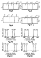
- Fig. 1 is a side, elevational schematic illustration of a system for applying a flux coating with an airless spray gun operated by an improved controller onto a circuit board being transported by a conveyor through a coating chamber, in accordance with the invention;
- Fig. 2A, 2B, and 2C show the position of the spray gun with respect to the underside of a circuit board shown in cross section at three consecutive on pulses of the gun; and
- Fig. 3 shows a plan view of a plurality of circuit boards carried on a pallet;
- Fig. 4 shows a plan view of a circuit board spayed by a pulse pattern having three zones of different length receiving different amounts of spray;
- Fig. 5 shows a plan view of a plurality of circuit boards carried on a pallet with each board being sprayed by a pulse pattern having three zones of different length receiving different amounts of spray;
- Fig. 6 shows a plan view of a plurality of circuit boards carried on a pallet a vacant space between two of the boards;
- Figs. 7A and 7B show encoder correlated plots of spray gun actuation for the present invention; and
- Figs. 7C and 7D show encoder correlated plots of spray gun actuation for the prior art controller.
-
- Referring to Fig. 1, there is shown a schematic illustration of
system 10 for applying a flux coating to a substrate such as acircuit board 12.System 10 includes aconveyor 14 fortransporting circuit board 12 through aflux coating chamber 16 in a direction of travel indicated byarrow 18. Aspray gun 20 having anozzle 22 is disposed withincoating chamber 16 and emits aliquid spray pattern 24 fromnozzle 22. Acontrol system 26 is operatively connected tospray gun 20 for intermittentlypulsing gun 20 on and off to coat overlapping sections of the undersurface ofcircuit board 12 in response tocircuit board 12 moving a predetermined distance throughcoating chamber 16. Anoverspray collection system 28, located withincoating chamber 16, collects oversprayed flux and exhausts it through avent 30 fromcoating chamber 16. - As in the prior art,
flux coating chamber 16 is located between an assembly station (not shown), wherecircuit components 54 are mounted oncircuit board 12 with theirleads 39 inserted into through-holes 41 extending throughboard 12, as shown in Figs. 2A, 2B, and 2C, and a preheat station (not shown) directly downstream fromcoating chamber 16 where the board, subsequent to being coated with a solder flux, is heated to a predetermined temperature which prevents damage from a high thermal gradient created when the board is passed through a conventional wave solder machine (not shown). -
Flux coating chamber 16 is formed with afront wall 34, and arear wall 32 provided with an inlet opening 36 and an outlet opening 38, respectively, through whichconveyor 14 passes.Conveyor 14 includes spaced coplanar conveyor chains 40 (only one being illustrated) which move in the direction oftravel 18.Chains 40 each carry a plurality of equallyspaced tabs 42, each with afinger 44 at its bottom which projects inwardly from the chain to which it is secured so as to point towards the fingers associated with the tabs (not shown) carried by the other chain (not shown).Fingers 44 serve to engage opposite edges ofcircuit board 12. Thechains 40 are driven jointly, by a variable-speed electric motor (not shown). Whenchains 40 are driven in the direction indicated by thearrow 18, eachcircuit board 12 is carried through theflux coating chamber 16 and sprayed with aliquid spray pattern 24 dispensed bynozzle 22 ofspray gun 20. After leavingflux chamber 16 through outlet opening 38, eachcircuit board 12 is transported through a preheat chamber (not shown) and then through the solder wave (not shown) for soldering. - Referring to Figs. 1, 2A, 2B, and 2C, a
conventional circuit board 12 is comprised of a sheet of insulative material, i.e. epoxy resin, having leading and trailingends holes 41 extend between the coplanarupper surface 50 andundersurface 52 ofboard 12. Each through-hole 41 is plated with alayer 43 of metal that is joined to a pair of spaced metallized areas (not shown), located on theopposite surfaces surfaces -
Circuit components 54 are mounted on theupper side 50 ofcircuit board 12 by means ofleads 39 passing through the through-holes 41 and soldered in place to assure a solid mechanical and electrical bond between each lead and the metal layer in each corresponding through-hole. The soldering is preferably done in an automatic fashion, such as by passing thecircuit board 12 over a wave of molten solder in a wave soldering machine (not shown) so that the wave of solder contacts theundersurface 52 of the board and is drawn up into each through-hole 41 by wetting forces to bond theleads 39 to the board. - Prior to soldering, solder flux is applied to the
undersurface 52 of thecircuit board 12 so that during the subsequent soldering operation, the solder will wet theleads 39, the metal layer within the through-holes 41 and the metallized areas. To assure a solid mechanical and electrical bond between theleads 39 and theboard 12, flux is preferably sprayed into the through-holes 41 after the leads are already in place. - A principle feature of this invention is the use of a
spray gun 20 disposed withincoating chamber 16 to apply a coating material such as solder flux, preferably a low-solid, or no-clean flux. While the invention is directed to the application of a flux material, it is within the scope of the invention to apply other types of liquid coating material. Thespray gun 20 is an on/off device and sprays the same volume of solder flux for the same time period in which it is open. Thespray gun 20 can be a Nordson Model A7A gun equipped with a Nordson Cross-Cut ® nozzle, manufactured by Nordson Corporation of Westlake, Ohio, the assignee of the present invention.Spray gun 20 uses a spray coating technique called airless atomization whereby the liquid upstream of the nozzle orifice is hydrostatically pressurized to expand after it exits the nozzle orifice into the air at ambient pressure so that the liquid stream expands and is atomized by the hydraulic force alone.Spray gun 20 is mounted on a gun mounting fixture (not shown) to vary the distance and to center thegun nozzle 22 with respect toundersurface 52 ofcircuit board 12. - Another aspect of the invention is that the solder flux is pulsed onto the
undersurface 52 ofboard 12 to ensure that the coating is uniformly applied across theundersurface 52 of the board without generating undue overspray. Pulsing in combination with a high pressure spray also ensures effective penetration of through-holes 41 incircuit board 12 because the flux impacts each through-hole inboard 12 from more than one angle, since the board is moving and thegun 20 is fixed. - As illustrated in Fig. 1,
board 12 is transferred in the direction ofarrow 18.Board 12 is sprayed with the solder flux byspray gun 20 which in turn is controlled bycontrol system 26. Thecontrol system 26 includes asensor 56 which is connected to acontroller 60 by aline 58. A first distance between thesensor 56 and thenozzle 22 ofspray gun 20 is programmed intocontroller 60. More typically, the first distance is set betweensensor 56 and thefront edge 24A ofspray pattern 24. When theleading end 46 ofcircuit board 12 passes undersensor 56, the sensor is activated until the trailingedge 48 of the board passes the sensor as the board moves in the direction oftravel 18.Sensor 56 outputs a length signal throughline 58 tocontroller 60 corresponding to a second distance equal to the length ofboard 12.Sensor 56 is positioned upstream from the location ofspray gun 20 to prevent overspray fromspray gun 20 coating the sensor.Control system 26 includes anencoder 62 disposed adjacent and preferably connected directly toconveyor 14.Encoder 62 outputs a number of encoder pulse (ep) signals tocontroller 60 through line 64 corresponding to the distance of travel ofconveyor 14. - In a
first embodiment controller 60 accesses a pulsing program from a conventional means, such as acomputer 66, throughline 68. The pulsing program enables an operator to input, the distance between thesensor 56 and thenozzle 22. If desired, the distance can be measured between thesensor 56 and the position where theforward edge 24A of thespray pattern 24 contacts the underside ofboard 12. Also, the operator inputs a selected period of time for pulsingspray gun 20 on, and a predetermined number of encoder pulse signals corresponding to the distance between the locations on thecircuit board 12 from when the spray gun is pulsed on and then pulsed on again. The predetermined number of encoder pulse signals are counted from whenever the spray gun is pulsed on. - During the operation of the first embodiment, the
control system 26, after having the first distance between thesensor 56 and theforward edge 24A of thespray pattern 24, the selected period of time and the predetermined number of encoder pulse signals already inputted into the pulsing program as mentioned above, is activated when acircuit board 12 is moved byconveyor 14 undersensor 56.Sensor 56 is then activated to sense the length ofcircuit board 12 carried onconveyor 14 and to output a length signal corresponding to a second distance between theleading edge 46 and the trailingedge 48 of the circuit board intoline 58. The length signal is inputted intocontroller 60 which in response thereto outputs a trigger signal for pulsing thespray gun 20 on for the selected period of time after theleading edge 46 ofcircuit board 12 moves the first distance. Then, aftercircuit board 12 travels a distance corresponding to the predetermined number of encoder pulse signals counted from whenspray gun 20 is pulsed on,controller 60 outputs another trigger signal for the selected period of time and thecircuit board 12 moves a distance corresponding to the predetermined number of encoder pulse signals counted from when the latter trigger signal. This sequence of trigger signals is repeated until thecircuit board 12 moves a distance corresponding to the length signal being output by thesensor 56 when thecontroller 60 stops outputting trigger signals until the next circuit board passes undersensor 56 to repeat the sequence again. - The
control system 26 provides a unique benefit that thecircuit board 12 will be coated with the same volume of solder flux per unit length irrespective of the speed of theconveyor 14 or the length of the circuit board. This can be understood by the comparison of the following two examples using arbitrary distances and times. - In example 1 relating to the
first embodiment conveyor 14 is set to move at 100 encoder pulses per second (ep/sec).Encoder 62 can be setup so thatconveyor 14 moves 1 inch (2.54 cm) for every 100 encoder pulses (ep). As shown in Fig. 2A and Fig. 7A,spray gun 20 is pulsed on for selected period of time of 50 milliseconds (.050 sec) after theleading edge 46 ofcircuit board 12 moves the first distance, for example 600 ep (6 inches (15.24 cm)), fromsensor 56 to the location where thefront edge 24A ofspray pattern 24 contacts theunderside 52 of the board. The spray is thus on .050 sec and is repeated every 50 ep while the board moves .05 inches (0.127 cm). The width of thespray pattern 24, i.e., betweenside edge pattern 24 is diagrammatically shown to be wider for purposes of illustration. The width of the coating applied to the undersurface of thecircuit board 12 in this example is thus 1.55 inches (3.937 cm). After thecircuit board 12 has moved a distance equal to 50 ep (0.5 inches (1.27 cm)) from the position of when the gun is initially pulsed on,spray gun 20 is pulsed on again for .05 sec and the cycle or sequence repeats every 50 ep. The next spray pulse is pulsed on again and coats a second section for 1.5 inches (3.81 cm) plus .05 inches (0.127 cm) of board travel which overlaps the first section. Since the side edge of the spray pulse is approximately 1.5 inches (3.81 cm) in width and since the second spray pulse will be actuated for .050 sec at 0.5 inches (1.27 cm) from the start of the first spray pulse, the first and second sections and will overlap by approximately 1.0 inches (2.54 cm). - In example 2 relating to the first embodiment as shown in Fig. 7B, the conveyor is set to move at 200 ep/sec.
Encoder 62 remains setup so thatconveyor 14 moves 1 inch (2.54 cm) for every 100 encoder pulses (ep). Thespray gun 20 is pulsed on for selected period of time of 50 milliseconds (.050 sec) after theleading edge 46 of thecircuit board 12 moves the first distance, for example 600 ep (6 inches (15.24 cm)) fromsensor 56 to thefront edge 24A ofspray pattern 24. The spray is thus on while the board moves .10 (0.254 cm) inches. The width of thespray pattern 24, i.e., betweenside edge circuit board 12 in this example is thus 1.60 inches (4.064 cm). After thecircuit board 12 has moved a distance equal to 50 ep (.50 inches (1.27 cm)) from the position of when the gun is initially pulsed on,spray gun 20 is pulsed on again for .050 sec and the cycle or sequence repeats every 50 ep. The next spray pulse is pulsed on again and coats a second section for 1.5 inches (3.81 cm) plus .10 inches (0.254 cm) of board travel which overlaps the first section. Since the side edge of the spray pulse is approximately 1.5 inches (3.81 cm) in width and since the second spray pulse will be actuated for .050 sec at .5 inches (1.27 cm) from the start of the first spray pulse, the first and second sections will still overlap by approximately 1.0 inches. - Using the prior art controller as described in Patent No. 5,415,337, the controller outputs a trigger signal for pulsing
spray gun 20 on for a selected number of encoder pulses and then triggers the spray gun off for a certain number of counts from encoder 128. This continues for a preprogramed distance. The prior art control system willcoat circuit board 12 with a different volume of solder flux per unit length depending on the speed of the conveyor. This can be understood by the comparison of the following two examples using arbitrary distances and times similar to those used in describing the first embodiment above. - In a third example relating to the prior art controller, as shown in Fig. 7C, the encoder remains setup so that conveyor moves 1 inch for every 100 encoder pulses (ep) and the conveyor is set to move at a desired speed, such as for example, 100 ep/sec or one inch per second (2.54 cm/g). At this speed, the encoder generates an encoder pulse for every .01 inches (0.0254 cm) of conveyor movement. The gun is pulsed open for 5 ep or .05 inches (0.127 cm) of conveyor movement. The period of time that the gun is open is .050 seconds. Then the controller closes the gun for 50 ep or .5 inches (1.27 cm) of board movement. The width of the spray pattern between
side edge circuit board 12 in this example is thus 1.55 inches (3.937 cm). After thecircuit board 12 has moved a distance equal to 50 ep (.5 inches (1.27 cm)) from the position of when the gun is pulsed off,spray gun 20 is pulsed on again for 5 ep or .05 inches (0.127 cm) of conveyor movement coats a second section for 1.5 inches (3.81 cm) plus .05 inches (0.127 cm) of board travel which overlaps the first section. Then, the gun is pulsed off for 50 ep and the cycle or sequence repeats itself until the end of the board is sensed by the sensor. Since the side edge of the spray pulse is approximately 1.5 inches (3.81 cm) in width and since the second spray pulse will be actuated for 0.05 inches (0.127 cm), after the start of the first spray pulse, the first and second sections will still overlap by approximately 1.0 inches (2.54 cm). - In a fourth example relating to the prior art controller, as shown in Fig. 7D, the encoder remains setup so that conveyor moves 1 inch (2.54 cm) for every 100 encoder pulses (ep) and the conveyor is set to move at a desired speed, such as for example, 200 ep/sec or two inches (5.08 cm) per second. The encoder generates an encoder pulse for every .01 inches (0.0254 cm) of conveyor movement. The gun is pulsed open for 5 ep or .05 (0.127 cm) inches of conveyor movement. Note, however that the gun is only on for .025 sec as compared with .050 sec in Example 3. Since the volume of solder flux dispensed by the gun in the same period of time does not change, in Example 4 about one half of the volume of solder flux is coated onto the same length of board as coated onto the board of Example 3 where the board is moving at half the speed of the board in Example 4. The prior art controller continues the sequence by closing the gun for 50 ep or .5 inches (1.27 cm) of board movement. The width of the spray pattern between
side edge circuit board 12 in this example is thus 1.55 inches (3.937 cm). After thecircuit board 12 has moved a distance equal to 50 ep (.5 inches (1.27 cm)) from the position of when the gun is pulsed off,spray gun 20 is pulsed on again for 5 ep or .05 inches (0.127 cm) of conveyor movement coats a second section for 1.5 inches (3.81 cm) plus .05 inches (0.127 cm) of board travel which overlaps the first section. Then, the gun is pulsed off for 50 ep and the cycle or sequence repeats itself until the end of the preprogramed distance. Since the side edge of the spray pulse is approximately 1.5 inches (3.81 cm) in width and since the second spray pulse will be actuated for 0.05 inches (0.127 cm), after the start of the first spray pulse, the first and second sections will still overlap by approximately 1.0 inches (2.54 cm). However because of the increased speed of the conveyor, only one half of the amount of solder flux will be coated to the underside of the board. - Another aspect of the first embodiment is the ability to program in the pulsing program a lead distance of a desired number of encoder pulses which represent an additional distance that the circuit board travels before the spray gun is pulsed on. This feature is useful to account for the width of the spray pattern so that the spray does not extend past the leading
edge 46 ofboard 12 as overspray. Also, this feature is useful whenseveral circuit boards 12 are carried on apallet 70, as illustrated in Fig. 3.Pallet 70 has afront rail 72 and arear rail 74 and thecircuit boards 12 are abutted against each other therebetween. In order that thefront rail 72 is not sprayed, the lead distance is programmed into the pulse program so that the gun is not pulsed on until the front rail ofpallet 70 moves a number of encoder pulses equal to both the predetermined distance betweensensor 56 and thenozzle 22 plus the width offront rail 72. In addition, the pulsing program can include a lag distance of a desired number of encoder pulses which represent the width ofrear rail 74. In order that therear rail 74 is not sprayed, the lag distance is programmed into the pulse program so thatgun 20 is not pulsed on whenpallet 70 moves a second distance between leadingedge 46 and trailingedge 48 ofcircuit board 12 less the lag distance. - Another feature of the first embodiment is the provision of a minimum trigger distance in encoder pulses. If the
sensor 56 turns on or off for the minimum trigger distance, the signal is ignored and does not effect the control function ofcontroller 60. For example, if acircuit board 12 has an open area whose length is less than the minimum trigger distance, the signal fromsensor 56 that would indicate the presence of the trailing edge is less than the minimum trigger distance and does not activate thecontroller 60. - In a
second embodiment controller 60 accesses a pulsing program with a pattern control mode from a conventional means, such as acomputer 66, throughline 68. The pattern control mode pulsing program enables an operator to input a pulsing pattern of a plurality of zones each having a different pulse pattern (period of time that the gun is pulsed on and predetermined number of encoder pulse signals for the length of each zone) to be sprayed on the circuit board. After the pulsing pattern is sprayed, the pulsing pattern repeats itself until the end of the board. While in a typical application the pulsing pattern includes two or three different zones programmed into the pattern control mode pulsing program, it is possible to program in addition zones the pulsing pattern as required. The pattern control mode pulsing program also enables an operator to input a predetermined number of encoder pulse signals corresponding to a second distance between leading edge 46' and trailing edge 48' of circuit board 12', as shown in Fig. 4. Throughout the specification, primed numbers represent structural elements which are substantially identical to structural elements represented by the same unprimed number. - During the operation of the second embodiment, the
control system 26, after having the first distance between thesensor 56 and thenozzle 22 or theforward edge 24A of thespray pattern 24, the selected period of pulse on time and the predetermined number of encoder pulse signals for each plurality of zones A, B, C, as shown in Fig. 4, of the pulsing pattern already inputted into the pulsing program as mentioned above, is activated whenconveyor 14 moves a circuit board 12' undersensor 56.Sensor 56 is then activated to sense the leading edge 46' of the circuit board 12' carried onconveyor 14 and to output a sensor signal intoline 58. The sensor signal is inputted intocontroller 60 which in response thereto outputs a first trigger signal for pulsing thespray gun 20 on for a first period of time during the movement of circuit board 12' for a first predetermined number of encoder pulses corresponding to the length of the first zone A, then a second trigger signal for pulsing thespray gun 20 on for a second period of time during the movement of the circuit board for a second predetermined number of encoder pulses corresponding to the length of the second zone B, then a third trigger signal for pulsing thespray gun 20 on for a third period of time during the movement of the circuit board for a third predetermined number of encoder pulses corresponding to the length of the third zone C. Then the program repeats the sequence and applies the pulsing pattern for the next circuit board passing undersensor 56. - Another aspect of the second embodiment is the ability to program in the pulsing program a lead distance of a desired number of encoder pulses which represent an additional distance that circuit board 12' travels before
spray gun 20 is pulsed on. This feature is useful to account for the width of the spray pattern so that the spray does not cross the leading edge 46' of the board 12' as overspray. Also, this feature is useful when several circuit boards 12' are carried on a pallet 70', as illustrated in Fig. 5. Pallet 70' has a front rail 72' and a rear rail 74' and the circuit boards 12' are abutted against each other therebetween. In order that front rail 72' is not sprayed, the lead distance is programmed into the pattern control mode pulsing program so that the spray gun is not pulsed on until the front rail 72' of pallet 70' moves a number of encoder pulses equal to both the predetermined distance from thesensor 56 tonozzle 22 plus the width of the front rail. In addition, the pattern control mode pulsing program can include a lag distance of a desired number of encoder pulses which represent the width of rear rail 74'. In order that the rear rail 74' is not sprayed, the lag distance is programmed into the pulse program so that the gun is not pulsed on when pallet 70' moves a second distance between the leading edge 46' and trailing edge 48' of circuit board 12' less the lag distance. - Another feature of the pattern control mode pulsing program is the provision of a minimum trigger distance in encoder pulses. If
sensor 56 turns on or off for the minimum trigger distance, the signal is ignored and does not effect the control function ofcontroller 60. For example, if the circuit boards 12' are loaded on pallet 70' so that a vacant space 76 exists between the trailing edge 48' of circuit board 12' and the leading edge 46' of the adjacent circuit board, as shown in Fig. 6, the controller does not stop pulsing the gun on because the length of the vacant space is less than the minimum trigger distance. In another example, when the width of the rear rail 74' is less than the minimum trigger distance, the signal fromsensor 56 is less than the minimum trigger distance and does not activate thecontroller 60. - It is apparent that there has been provided a system and method for applying a flux coating to a circuit board that satisfy the objects, means and advantages set forth hereinbefore. According to one embodiment, a control system operates a spray gun to apply an even coating of flux to a circuit board or a plurality of different length circuit boards irrespective of the speed that the circuit board(s) move through the coating chamber. In a second embodiment, the control system pulses the spray gun on and off with a pulsing pattern that coats a plurality of zones of a circuit board with spray patterns of flux of different length and thickness.
Claims (12)
- A system (10) for controlling the application of a coating material to a substrate (12, 12') having a leading edge (46, 46') and a trailing edge (48, 48'), the system comprising a conveyor (14) for transporting the substrate (12) in a direction of travel, a spray gun (20) disposed adjacent to the conveyor (14), the spray gun (20) emitting a spray pattern of coating material for application to the substrate (12, 12'), an encoder (62) disposed adjacent the conveyor (14) for outputting a number of pulse signals correlated to the distance of travel of the conveyor (14), a sensor (56) disposed adjacent to the conveyor (14) and upstream of the spray gun (20) a first distance and a controller (60) operatively connected to the spray gun (20), the encoder (62) and the sensor (56), the controller (60) receiving the pulse signals from the encoder (62) and outputting to the spray gun (20) a trigger signal after the leading edge (46, 46') of the substrate (12, 12') moves the first distance, characterised in that the sensor (56) is for measuring the length of the substrate (12, 12') and for outputting a length signal corresponding to the length of the substrate, the controller (60) receiving the length signal from the sensor (56) and in that the controller is programmed to output to the spray gun (20) at least a first and a second plurality of trigger signals, the first plurality of trigger signals being outputted during a time period correlated to the length of a first portion (A) of the substrate (12,12'), each of the first plurality of trigger signals starting after the substrate (12, 12') moves a first predetermined distance and lasting a first predetermined length of time, and the second plurality of trigger signals being outputted during a time period correlated to the length of a second portion (B) of the substrate (12, 12') and starting after the leading edge (46, 46') of the substrate (12, 12') moves a distance equal to the first portion (A), each of the second plurality of trigger signals starting after the substrate (12, 12') moves a second predetermined distance and lasting a second predetermined length of time.
- A system as claimed in Claim 1 wherein the first predetermined distance is not equal to the second predetermined distance.
- A system as claimed in either Claim 1 or Claim 2 wherein the first predetermined length of time is not equal to the second predetermined length of time.
- A system as claimed in any preceding Claim wherein the spray gun (20) is on only during the receipt of the first and second plurality of trigger signals.
- A system as claimed in any preceding Claim wherein the first plurality of trigger signals start after the leading edge (46, 46') of the substrate (12, 12') moves the first distance plus an additional distance.
- A system as claimed in any preceding Claim wherein the second plurality of trigger signals ends after the leading edge (46, 46') of the substrate (12, 12') moves a distance equal to the length of the substrate minus an additional distance.
- A system as claimed in any preceding Claim wherein the controller (60) outputs a recurring sequence of at least the first and the second plurality of trigger signals after the leading edge (46, 46') of the substrate (12, 12') moves the first distance.
- A method of controlling the application of a coating material to a substrate (12, 12') having a leading edge (46, 46') and a trailing edge (48, 48'), the method comprising the steps of determining a first distance from a sensor (56) to a spray gun (20), conveying the substrate (12, 12') on a conveyor (14) toward the sensor (56) and the spray gun (20), outputting a number of pulse signals correlated to the distance of travel of the conveyor, outputting a trigger signal in response to a signal from the sensor (56) and the pulse signals, and controlling the operation of the spray gun (20) in response to the trigger signal characterised in that the method includes measuring the length of the substrate (12, 12') on the conveyor (14) and outputting a length signal corresponding to the length of the substrate; in that at least a first and a second plurality of trigger signals are output in response to the length signal and the pulse signals, the operation of the spray gun (20) being controlled in response to the first and second plurality of trigger signals; and in that the first plurality of trigger signals is output during a time period correlated to the length of a first portion and starting after the leading edge (46, 46') of the substrate (12, 12') moves the first distance, each of the first plurality of trigger signals starting after the substrate moves a first predetermined distance and lasting a first predetermined length of time, and the second plurality of trigger signals is output during a time period correlated to the length of a second portion (B) of the substrate (12, 12') and starting after the leading edge (46, 46') of the substrate (12, 12') moves a distance equal to the first portion, each of said second plurality of trigger signals starting after the substrate moves a second predetermined distance and lasting a second predetermined length of time.
- The method of Claim 8 including the step of starting the first plurality of trigger signals after the substrate moves the first distance plus an additional lead distance.
- The method of either Claim 8 or Claim 9 including the step of ending the second plurality of trigger signals after the substrate moves a distance equal to the length of the substrate, less an additional lag distance.
- The method as claimed in any one of Claims 8 to 10 wherein the controller outputs a third plurality of trigger signals, each starting after the substrate moves a third predetermined distance and lasting a third predetermined length of time.
- The method of any one of Claims 8 to 10 wherein the coating material is a flux coating liquid and the substrate is a circuit board.
Applications Claiming Priority (2)
| Application Number | Priority Date | Filing Date | Title |
|---|---|---|---|
| US672098 | 1996-06-27 | ||
| US08/672,098 US5938848A (en) | 1996-06-27 | 1996-06-27 | Method and control system for applying solder flux to a printed circuit |
Publications (2)
| Publication Number | Publication Date |
|---|---|
| EP0815999A1 EP0815999A1 (en) | 1998-01-07 |
| EP0815999B1 true EP0815999B1 (en) | 2003-08-20 |
Family
ID=24697138
Family Applications (1)
| Application Number | Title | Priority Date | Filing Date |
|---|---|---|---|
| EP97304323A Expired - Lifetime EP0815999B1 (en) | 1996-06-27 | 1997-06-19 | Method & control system for applying solder flux to a printed circuit |
Country Status (6)
| Country | Link |
|---|---|
| US (2) | US5938848A (en) |
| EP (1) | EP0815999B1 (en) |
| JP (1) | JPH1098255A (en) |
| KR (1) | KR980007896A (en) |
| CA (1) | CA2207860A1 (en) |
| DE (1) | DE69724194T2 (en) |
Families Citing this family (17)
| Publication number | Priority date | Publication date | Assignee | Title |
|---|---|---|---|---|
| US6190727B1 (en) * | 1998-10-30 | 2001-02-20 | Georgia-Pacific Corporation | Liquid coating spray applicator and method providing automatic spread rate control |
| US6321591B1 (en) * | 1999-02-22 | 2001-11-27 | Electronic Controls Design, Inc. | Method and apparatus for measuring spray from a liquid dispensing system |
| US6722553B2 (en) | 2000-08-24 | 2004-04-20 | Advanced Micro Devices, Inc. | Controlled and programmed deposition of flux on a flip-chip die by spraying |
| JP2002172459A (en) * | 2000-09-26 | 2002-06-18 | Sony Corp | Soldering equipment |
| US20030222120A1 (en) * | 2002-05-29 | 2003-12-04 | Kaiser Joseph G. | Devices for and methods of casting and bonding a molten material onto one or more surfaces of a moving substrate |
| US20060273138A1 (en) * | 2005-06-07 | 2006-12-07 | Samsung Electronics Co., Ltd. | Soldering apparatus for printed circuit board, soldering method for printed circuit board and soldering cream printing unit for soldering printed circuit board |
| TWI257999B (en) * | 2005-07-29 | 2006-07-11 | Quanta Display Inc | Device for detecting a cracked substrate |
| WO2010044904A1 (en) * | 2008-10-17 | 2010-04-22 | Ncc Nano, Llc | Method for reducing thin films on low temperature substrates |
| CN101850313A (en) * | 2009-04-01 | 2010-10-06 | 鸿富锦精密工业(深圳)有限公司 | Flux spraying control system and method |
| CN104133389A (en) * | 2012-03-30 | 2014-11-05 | 珠海晶英科技有限公司 | Programmable sprayer and control method thereof |
| CN105345214A (en) * | 2015-11-15 | 2016-02-24 | 合肥锦利丰机械有限公司 | Automatic fixed-point welding production line for copper pipe |
| CN105537036B (en) * | 2015-12-11 | 2016-11-23 | 珠海晶英科技有限公司 | A kind of Programmable atomizer and control method thereof |
| JP7085138B2 (en) * | 2018-11-27 | 2022-06-16 | 三浦工業株式会社 | Spray flux coating device |
| US10549481B1 (en) * | 2018-12-21 | 2020-02-04 | Dukane Ias, Llc | Systems and methods for low initial weld speed in ultrasonic welding |
| FR3093181B1 (en) | 2019-02-25 | 2021-05-07 | Moving Magnet Tech | Position sensor, in particular intended for detecting the torsion of a steering column. |
| CN113769919B (en) * | 2021-09-14 | 2022-12-30 | 江西景旺精密电路有限公司 | Method and device for spraying ink on circuit board, computer equipment and storage medium |
| CN114669413A (en) * | 2022-03-23 | 2022-06-28 | 美的集团股份有限公司 | Selective spraying device, method and wave soldering equipment |
Family Cites Families (12)
| Publication number | Priority date | Publication date | Assignee | Title |
|---|---|---|---|---|
| US4164001A (en) * | 1978-04-04 | 1979-08-07 | Patnaude Edmond J | Speed compensating control system |
| DE3148541C2 (en) * | 1981-12-08 | 1984-03-01 | Ransburg-Gema AG, 9015 St.Gallen | Spray coating system |
| US4419384A (en) * | 1982-09-27 | 1983-12-06 | Armstrong World Industries, Inc. | Apparatus and process for ultrasonically identifying and coating articles having differing characteristics |
| US4821948A (en) * | 1988-04-06 | 1989-04-18 | American Telephone And Telegraph Company | Method and apparatus for applying flux to a substrate |
| US5217745A (en) * | 1989-06-28 | 1993-06-08 | Baldev Patel | Method and apparatus for applying a programmable pattern to a succession of moving objects |
| JPH07108455B2 (en) * | 1991-07-11 | 1995-11-22 | 株式会社タムラ製作所 | Spray control method of spray flux |
| US5226962A (en) * | 1991-11-08 | 1993-07-13 | Electrovert U.S.A. Corp. | Flux applicator system |
| WO1994004305A1 (en) * | 1992-08-18 | 1994-03-03 | Precision Dispensing Equipment, Inc. | Method and apparatus for applying flux |
| GB2275638B (en) * | 1993-03-05 | 1996-05-15 | Invicta Contract Eng Ltd | Improvements in sprayers |
| JP2815789B2 (en) * | 1993-09-08 | 1998-10-27 | 日本電熱計器株式会社 | Flux coating method |
| US5368219A (en) * | 1993-11-04 | 1994-11-29 | Nordson Corporation | Method and apparatus for applying solder flux to a printed circuit |
| JPH0846339A (en) * | 1994-07-30 | 1996-02-16 | Sony Corp | Spray type solder flux application system |
-
1996
- 1996-06-27 US US08/672,098 patent/US5938848A/en not_active Expired - Fee Related
-
1997
- 1997-06-17 CA CA002207860A patent/CA2207860A1/en not_active Abandoned
- 1997-06-19 EP EP97304323A patent/EP0815999B1/en not_active Expired - Lifetime
- 1997-06-19 DE DE69724194T patent/DE69724194T2/en not_active Expired - Fee Related
- 1997-06-27 JP JP9170820A patent/JPH1098255A/en not_active Withdrawn
- 1997-06-27 KR KR1019970031027A patent/KR980007896A/en not_active Abandoned
-
1999
- 1999-08-16 US US09/375,131 patent/US6265017B1/en not_active Expired - Fee Related
Also Published As
| Publication number | Publication date |
|---|---|
| US5938848A (en) | 1999-08-17 |
| DE69724194T2 (en) | 2004-06-09 |
| DE69724194D1 (en) | 2003-09-25 |
| CA2207860A1 (en) | 1997-12-27 |
| EP0815999A1 (en) | 1998-01-07 |
| US6265017B1 (en) | 2001-07-24 |
| KR980007896A (en) | 1998-03-30 |
| JPH1098255A (en) | 1998-04-14 |
Similar Documents
| Publication | Publication Date | Title |
|---|---|---|
| US5368219A (en) | Method and apparatus for applying solder flux to a printed circuit | |
| US5938848A (en) | Method and control system for applying solder flux to a printed circuit | |
| JP2020022965A (en) | Coating method and coating system | |
| US4490129A (en) | Forming cartons | |
| EP0480016B1 (en) | Solder flux applicator | |
| JP2003506210A (en) | Method and apparatus for forming a peelable protective layer for surfaces, in particular lacquered surfaces of motor vehicle bodies | |
| JP4022785B2 (en) | Method for detecting misalignment of coating pattern and correction method thereof | |
| WO1994004305A1 (en) | Method and apparatus for applying flux | |
| JP2007524506A (en) | Conformal coating using a non-contact dispensing method | |
| JP3173814B2 (en) | Flux coating method | |
| JPH10314640A (en) | Method and apparatus for applying adhesive | |
| CA1091102A (en) | Mass wave soldering system | |
| JP2006181625A (en) | Flux application method | |
| JP3090228B2 (en) | Automatic coating equipment | |
| JP2820595B2 (en) | Spray type flux coating device and coating method | |
| JPH0719570Y2 (en) | Spray gun cleaning device for automatic coating equipment | |
| GB2103145A (en) | Forming cartons | |
| JPS5819006Y2 (en) | Flux coating equipment | |
| JPH07254776A (en) | Flux applicator | |
| JPH02241570A (en) | Dispenser | |
| JPH10135618A (en) | Automatic soldering equipment and soldering method for printed board | |
| JPH05146726A (en) | Flux applying device | |
| JPH0245564B2 (en) | ||
| JP2005167001A (en) | Device and method for soldering substrate | |
| JPH10272393A (en) | Coating equipment |
Legal Events
| Date | Code | Title | Description |
|---|---|---|---|
| PUAI | Public reference made under article 153(3) epc to a published international application that has entered the european phase |
Free format text: ORIGINAL CODE: 0009012 |
|
| AK | Designated contracting states |
Kind code of ref document: A1 Designated state(s): DE FR GB IT |
|
| 17P | Request for examination filed |
Effective date: 19980316 |
|
| AKX | Designation fees paid |
Free format text: DE FR GB IT |
|
| RBV | Designated contracting states (corrected) |
Designated state(s): DE FR GB IT |
|
| 17Q | First examination report despatched |
Effective date: 19981221 |
|
| GRAH | Despatch of communication of intention to grant a patent |
Free format text: ORIGINAL CODE: EPIDOS IGRA |
|
| RIN1 | Information on inventor provided before grant (corrected) |
Inventor name: CHRISTYSON, RICHARD Inventor name: ROBERTS, DREW Inventor name: POWELL, JAMES Inventor name: BYERS, JOHN Inventor name: ZALEWSKI, KENNETH Inventor name: HOGAN, PATRICK T. |
|
| GRAH | Despatch of communication of intention to grant a patent |
Free format text: ORIGINAL CODE: EPIDOS IGRA |
|
| GRAA | (expected) grant |
Free format text: ORIGINAL CODE: 0009210 |
|
| AK | Designated contracting states |
Designated state(s): DE FR GB IT |
|
| REG | Reference to a national code |
Ref country code: GB Ref legal event code: FG4D |
|
| REF | Corresponds to: |
Ref document number: 69724194 Country of ref document: DE Date of ref document: 20030925 Kind code of ref document: P |
|
| ET | Fr: translation filed | ||
| PLBE | No opposition filed within time limit |
Free format text: ORIGINAL CODE: 0009261 |
|
| STAA | Information on the status of an ep patent application or granted ep patent |
Free format text: STATUS: NO OPPOSITION FILED WITHIN TIME LIMIT |
|
| 26N | No opposition filed |
Effective date: 20040524 |
|
| PGFP | Annual fee paid to national office [announced via postgrant information from national office to epo] |
Ref country code: GB Payment date: 20050606 Year of fee payment: 9 |
|
| PGFP | Annual fee paid to national office [announced via postgrant information from national office to epo] |
Ref country code: FR Payment date: 20050610 Year of fee payment: 9 |
|
| PGFP | Annual fee paid to national office [announced via postgrant information from national office to epo] |
Ref country code: DE Payment date: 20050613 Year of fee payment: 9 |
|
| PG25 | Lapsed in a contracting state [announced via postgrant information from national office to epo] |
Ref country code: GB Free format text: LAPSE BECAUSE OF NON-PAYMENT OF DUE FEES Effective date: 20060619 |
|
| PGFP | Annual fee paid to national office [announced via postgrant information from national office to epo] |
Ref country code: IT Payment date: 20060630 Year of fee payment: 10 |
|
| PG25 | Lapsed in a contracting state [announced via postgrant information from national office to epo] |
Ref country code: DE Free format text: LAPSE BECAUSE OF NON-PAYMENT OF DUE FEES Effective date: 20070103 |
|
| GBPC | Gb: european patent ceased through non-payment of renewal fee |
Effective date: 20060619 |
|
| REG | Reference to a national code |
Ref country code: FR Ref legal event code: ST Effective date: 20070228 |
|
| PG25 | Lapsed in a contracting state [announced via postgrant information from national office to epo] |
Ref country code: FR Free format text: LAPSE BECAUSE OF NON-PAYMENT OF DUE FEES Effective date: 20060630 |
|
| PG25 | Lapsed in a contracting state [announced via postgrant information from national office to epo] |
Ref country code: IT Free format text: LAPSE BECAUSE OF NON-PAYMENT OF DUE FEES Effective date: 20070619 |