EP0815988B1 - Method of force-fitting separate member into casting and apparatus therefor - Google Patents
Method of force-fitting separate member into casting and apparatus therefor Download PDFInfo
- Publication number
- EP0815988B1 EP0815988B1 EP97108798A EP97108798A EP0815988B1 EP 0815988 B1 EP0815988 B1 EP 0815988B1 EP 97108798 A EP97108798 A EP 97108798A EP 97108798 A EP97108798 A EP 97108798A EP 0815988 B1 EP0815988 B1 EP 0815988B1
- Authority
- EP
- European Patent Office
- Prior art keywords
- force
- casting
- fitting
- passage
- sliding member
- Prior art date
- Legal status (The legal status is an assumption and is not a legal conclusion. Google has not performed a legal analysis and makes no representation as to the accuracy of the status listed.)
- Expired - Lifetime
Links
- 238000005266 casting Methods 0.000 title claims description 123
- 238000000034 method Methods 0.000 title claims description 14
- 239000002184 metal Substances 0.000 claims description 39
- 229910052751 metal Inorganic materials 0.000 claims description 39
- 239000010720 hydraulic oil Substances 0.000 description 24
- 238000007711 solidification Methods 0.000 description 10
- 230000008023 solidification Effects 0.000 description 10
- 238000004519 manufacturing process Methods 0.000 description 4
- 238000010276 construction Methods 0.000 description 3
- 239000000110 cooling liquid Substances 0.000 description 3
- 230000002159 abnormal effect Effects 0.000 description 2
- 238000002347 injection Methods 0.000 description 2
- 239000007924 injection Substances 0.000 description 2
- 238000003754 machining Methods 0.000 description 2
- 238000012986 modification Methods 0.000 description 2
- 230000004048 modification Effects 0.000 description 2
- 239000003921 oil Substances 0.000 description 2
- 229910052776 Thorium Inorganic materials 0.000 description 1
- 238000010420 art technique Methods 0.000 description 1
- 238000005452 bending Methods 0.000 description 1
- 238000002485 combustion reaction Methods 0.000 description 1
- 230000005489 elastic deformation Effects 0.000 description 1
- 238000000465 moulding Methods 0.000 description 1
- 238000002360 preparation method Methods 0.000 description 1
Images





Classifications
-
- B—PERFORMING OPERATIONS; TRANSPORTING
- B22—CASTING; POWDER METALLURGY
- B22D—CASTING OF METALS; CASTING OF OTHER SUBSTANCES BY THE SAME PROCESSES OR DEVICES
- B22D17/00—Pressure die casting or injection die casting, i.e. casting in which the metal is forced into a mould under high pressure
Definitions
- This invention relates generally to a method and apparatus for force-fitting a separate member into a casting.
- a pipe is force-fitted into a casting so that a hose for supplying a cooling liquid to the cooling liquid passage is connected to the cylinder block through the pipe.
- a technique in which a passage is formed in a casting the passage being communicated with the outside of the casting at a hole formed at a surface of the casting, and later the hole is closed by force-fitting a separate member into the hole so that the passage closed at the surface of the casting is completed in the casting.
- the casting is taken out from a casting mold, the taken out casting is cooled, the cooled casting is transferred to a subsequent stage where a force-fitting portion of the casting into which the separate member is to be force-fitted is machined so as to be suitable for the force-fitting, and finally the separate member is force-fitted into the machined portion of the casting.
- the force-fitting portion is externally caulked after the force-fitting when the caulking is necessary, so that the separate member is prevented from falling off therefrom.
- a force-fitting interference needs to be rendered sufficiently large in order that the separate member is reliably force-fitted into the casting.
- the force-fitting interference refers to the difference between the outer diameter of the separate member and the inner diameter of a concave portion of the casting into which the separate member is to be force-fitted. The casting tends to be cracked or deformed when the force-fitting interference is rendered large.
- a casting machine with a force-fitting mechanism in accordance with a first embodiment of the present invention and a method carried out by the casting machine will be described with reference to FIGS.1 to 6.
- the casting machine with the force-fitting mechanism in accordance with the first embodiment is equipped with a fixed metal mold 12 and a movable metal mold 14 both of which constitute a casting mold 9.
- the fixed and movable molds 12 and 14 are clamped by a mold clamping mechanism (not shown). In this state, a cavity 16 is defined in the interior of the casting mold 9.
- the fixed mold 12 has a pin guide passage 12t formed in an upper portion of the fixed mold 12 to extend vertically along an extension line from the cavity 16, as viewed in FIG.1.
- a center slide pin 13 for defining a main passage Tm (see FIG.4) of a casting W is slidably accommodated in the pin guide passage 12t.
- the center slide pin 13 is connected at its upper end to an elevator mechanism (not shown) and has a lower distal end adapted to project a predetermined length out of the pin guide passage 12t into the cavity 16.
- the fixed mold 12 has a ball passage 12s formed in the upper portion thereof to be perpendicular to the pin guide passage 12t, as viewed in FIG.1.
- a set of balls 15 each serving as a closure member are accommodated in the ball passage 12s.
- the balls 15 are those used in a ball bearing, for example.
- a coil spring (not shown) is mounted to a right-hand end of the ball passage 12s for urging the balls 15 accommodated in the ball passage 12s toward the pin guide passage 12t.
- a cylinder, elastic member, magnet, etc. may be used instead of the coil spring.
- the self- weight of the balls 15 may be utilized for urging them toward the pin guide passage 12t.
- Each of the balls 15 serves as a separate member to be force-fitted into a casting, as will be described later.
- the fixed mold 12 has in its lower portion a lateral pin passage 12y formed to be parallel to the ball passage 12s, as viewed in FIG.1.
- a pressure pin 17 is slidably accommodated in the lateral pin passage 12y.
- the pressure pin 17 is driven by a pressure cylinder (not shown) so that its distal end projects a predetermined length into the cavity 16 to thereby support the distal end of the center slide pin 13 positioned in the cavity 16.
- First and second draw pins 18 and 19 are mounted on the movable mold 14 for defining first and second passages Th and Ts (see FIG.4) in the casting W respectively.
- the first draw pin 18 horizontally projects into the upper interior of the cavity 16, abutting against the side surface of the center slide pin 13, as viewed in FIG.1.
- the second draw pin 19 horizontally projects into the lower interior of the cavity 16, abutting against the distal end of the center slide pin 13 at the side opposite to the pressure pin 17.
- the elevator mechanism (not shown) is first operated to lower the center slide pin 13 so that the center slide pin projects into the cavity. In this state, the distal end of the pin 13 projects a predetermined length into the cavity 16.
- the pressure cylinder (not shown) is then operated so that the pressure pin 17 projects into the cavity 16, abutting at its distal end surface against the side surface of the distal end of the center slide pin 13.
- the mold clamping mechanism (not shown) is then operated to clamp the fixed and movable molds 12 and 14 together, as shown in FIG.1, such that the distal end surfaces of the first and second draw pins 18 and 19 are abutted against the side surface of the center slide pin 13.
- a predetermined amount of molten metal is supplied from an injection cylinder (not shown) into the cavity 16 at high speed, as shown in FIG.2. While the molten metal is injected into the cavity 16, a lateral force is applied to the center slide pin 13 by the flow of the molten metal. When the cavity is filled with the molten metal, the center slide pin 13 is free from the lateral force. When the center slide pin 13 is free from the lateral force, a pressure pin 17 is retreated (see FIG.3). Another predetermined amount of molten metal is supplemented between the center slide pin 13 and the retreated pressure pin 17, as shown in FIG.3. The supplemented molten metal is supplied from outside the cavity 16. The pressure pin 17 is re-advanced to apply pressure to the molten metal solidifying in the cavity 16 so that blowholes are crushed and the structure of the casting W is rendered sound.
- the center slide pin 13 is then moved upward to be thereby drawn out from the casting W when the molten metal in the cavity 16 is solidified with lapse of a predetermined time into such a degree as to maintain a certain shape. Consequently, the casting W is formed in the casting mold 9, as shown in FIG.4.
- the main passage Tm is formed in the casting W.
- the elevator mechanism is operated to move the center slide pin 13 upward so that its distal end is positioned higher than the ball passage 12s. More specifically, the ball passage 12s communicates with the pin guide passage 12t at a position between the distal end of the raised center slide pin 13 and the cavity 16. The first ball of the row of balls 15 in the ball passage 12s is pushed into the pin guide passage 12t when the distal end of the center slide pin 13 is moved upward to a position higher than the ball passage 12s (see FIG.4).
- the center slide pin 13 is lowered again from the above-described state so that the ball 15 supplied into the pin guide passage 12t is force-fitted into an upper end of the main passage Tm by the center slide pin 13. As a result, the end of the main passage Tm is closed by the hall 15. Thus, the separate member or the ball 15 is force-fitted into the concavity or the main passage Tm formed in the casting W while the casting W is enclosed in the casting mold 9.
- the center slide pin 13 is slightly moved upward to be drawn out from the casting W upon completion of the force-fitting of the ball 15 into the main passage Tm, as shown in FIG.6.
- the distal end of the center slide pin 13 is held at a position lower than the ball passage 12s such that an exit of the ball passage 12s is closed by the side wall of the center slide pin 13. In this state, the molds 12 and 14 arc opened.
- the separate member is force-fitted into the casting W while the latter is enclosed in the casting mold 9. While the casting W is enclosed in the casting mold, the metal of the casting is not so hard and the metal condition is suitable for press-fitting. Accordingly, the end of the passage need not he machined as conventionally executed, the manufacturing cost of the product can he reduced, and the manufacturing process and time can be shortened. Furthermore, the force-fitting of the separate member 15 is carried out before the casting W is taken out from the molds 12 and 14 or when the casting W is at a high temperature. Consequently, there arises no problem of crack, deformation, etc. of the casting W even when the force-fitting interference is set at a large value. Additionally, since the casting W has a larger shrinkable factor than the ball 5, the latter is securely fixed to the casting W when it is cooled.
- a sliding member dedicated to the force-fitting may be provided at the side opposite to the center slide pin 13 when a through hole is formed in the casting W by the center slide pin. In this case, too, the force-fitting can be executed while the casting is enclosed in the casting mold.
- FIGS.7 to 9(B) A second embodiment of the invention will be described with reference to FIGS.7 to 9(B).
- a casting machine with a force-fitting mechanism of the second embodiment is equipped with a fixed metal mold 112 and a movable metal mold 114.
- the fixed and movable molds 112 and 114 are clamped by a mold clamping mechanism (not shown).
- a longitudinally elongated cavity 116 serving as a product molding space is defined in the interior of the casting mold.
- the fixed mold 112 has a horizontally extending pin guide passage 112t formed therein to be continuous substantially perpendicularly to the upper interior of the cavity 116.
- the pin guide passage 112t is provided for guiding a slide pin 113 and has an inner diameter approximately equal to an outer diameter of the slide pin 113.
- the slide pin 113 is provided for forming in a casting W an opening Wt into which a pipe P is to be force-fitted and for force-fitting the pipe P into the opening Wt.
- the slide pin 113 is slidably accommodated in the pin guide passage 112t and connected at its proximal end 113m to a pushing cylinder 123.
- the fixed mold 112 has a recess 112a formed in one side thereof.
- the pushing cylinder 123 is accommodated in the recess 112a to be positioned coaxial with the slide pin 113.
- the pushing cylinder 123 is operated for moving the slide pin 113 forward and backward along the pin guide passage 112t.
- FIG.7 shows the condition where the slide pin 113 is in its forward end position.
- a pipe passage 125 is continuous perpendicularly to a middle portion of the pin guide passage 112t.
- the pipe passage 125 is provided for accommodating a plurality of pipes P therein in parallel with the slide pin 113.
- the pipe passage 125 has a substantially equal transverse dimension to the length of each pipe P and a width substantially equal to the outer diameter of each pipe P. Accordingly, the pipes P are accommodated in the pipe passage 125 to be arranged in parallel to the slide pin 113.
- the outer diameter of each pipe P is set to be substantially equal to an outer diameter of the slide pin 113.
- a coil spring (not shown) or the like is provided in the pipe passage 125 for urging the pipes P toward the pin passage 112t. Accordingly, one pipe P is automatically supplied to the pin guide passage 112t when the distal end of the slide pin 113 is moved backward behind the pipe passage 125.
- a cylinder, elastic member, etc. may be used instead of the coil spring.
- the self-weight of the pipes P may be utilized for urging them toward the pin guide passage 112t.
- a predetermined amount of molten metal is supplied from an injection cylinder (not shown) into the cavity 116 at high speed, as shown in FIG.7.
- the pushing cylinder 123 is driven so that the slide pin 113 is pulled out from the semi-solidified molten metal, as shown in FIG.8.
- the opening Wt is formed in the semi-solidified molten metal which will hereinafter be referred to as "casting W" and the exit of the pipe passage 125 is opened so that one pipe P is supplied from the pipe passage 125 to the pin guide passage 112t.
- the pushing cylinder 123 is driven again to move the slide pin 113 forward.
- the pipe P supplied to the pin guide passage 112t is then pushed by the slide pin 113 axially to be thereby force-fitted into the opening Wt of the casting W, as shown in FIG .9.
- the molten metal is completely solidified upon lapse of a predetermined time.
- the molds 112 and 114 are then opened and the casting W to which the pipe P is fixed is taken out from the molds.
- One cycle of the casting process is completed when the pushing cylinder 123 is driven to hold the slide pin 113 at the forward end position in preparation for the subsequent casting process.
- the pipe P is force-fitted into the opening Wt when the molten metal solidifies to such a degree as to maintain the certain shape in the cavity 116.
- the pipe P can be prevented from being subjected to the molten metal charging pressure and can be force-fitted into the casting W by a relatively smaller force. Consequently, the deformation of the pipe P or the like can be prevented. Furthermore, since the molten metal is prevented from entering the inside of the pipe P, the pipe can reliably be fixed to the casting W only if the pipe has a thickness sufficient for the force-fitting.
- a force-fitted portion Pi of the pipe P is cylindrical, whereas the slide pin 113 is provided with a draft on its distal end. Consequently, the opening Wt formed by the slide pin 113 has a diameter smaller by a shaded portion S than the force-fitted portion Pi of the pipe P, as shown in FIG.9(B).
- a radial pressure is applied to the shaded portion S by the pipe P such that the shaded portion S is squeezed. Consequently, the structure of the casting W is densified, and the degree of adhesion between the pipe P and the casting W can be improved.
- the degree of adhesion can further be improved by shrinkage due to solidification of the molten metal.
- the accuracy in machining the pipes P may be lower as compared with the prior art in which a pipe is force-fitted into a machined opening. Additionally, since the pipe P is force-fitted into the opening Wt before the molds 112 and 114 are opened, the casting W is peripherally backed up by the molds 112 and 114 during the force-fitting step. Consequently, occurrence of cracks in the casting due to the force-fitting can be restricted.
- FIGS.10 and 11 illustrate a third embodiment of the invention.
- a casting machine 200 of the third embodiment incorporates an improvement in the elevator mechanism for the center slide pin 13 of the casting machine 10 in the above-described first embodiment.
- the other construction of the casting machine 200 of the third embodiment is the same as that in the first embodiment. Accordingly, the identical parts are labeled by the same reference symbols in the third embodiment as in the first embodiment and the description of them will be eliminated.
- a center slide pin 213 of the casting machine 200 is connected at its proximal end to a piston rod 221 of a lift cylinder 220.
- the lift cylinder 220 is mounted to the top of the fixed mold 12 to be coaxial with the center slide pin 213.
- the lift cylinder 220 is operated to move the center slide pin 213 upward and downward along the pin guide passage 12t.
- the lift cylinder 220 has upper and lower hydraulic oil chambers 225 and 226.
- First and second hydraulic oil pipes 225p and 226p are connected to the upper and lower hydraulic oil chambers 225 and 226 respectively. Hydraulic oil is supplied through the first hydraulic oil pipe 225p to the upper hydraulic oil chamber 225 so that the center slide pin 213 is lowered.
- the hydraulic oil is supplied through the second hydraulic oil pipe 226p to the lower hydraulic oil chamber 226 so that the center slide pin 213 is moved upward.
- the first hydraulic oil pipe 225p is provided with a pressure sensor 230 for detecting pressure in the upper hydraulic oil chamber 225 and a flow rate control valve 235 for controlling the amount of the hydraulic oil supplied to the upper hydraulic oil chamber 225 per a unit time.
- the pressure sensor 230 detects the pressure in the upper hydraulic oil chamber 225, thereby generating a pressure signal representative of the pressure in the upper hydraulic oil chamber 225.
- the pressure signals are continuously inputted to a computer 240, which delivers a control signal so that the control valve 235 is remote controlled on the basis of the control signal.
- the hydraulic oil is supplied to the lower hydraulic oil chamber 226 of the lift cylinder 220 so that the center slide pin 213 is moved upward to be thereby pulled out from the casting W.
- a longitudinal main passage Tm is formed in the casting W.
- one of the balls 15 in the ball passage 12s is supplied into the pin guide passage 12t.
- the hydraulic oil is then supplied to the upper hydraulic oil chamber 225 of the lift cylinder 220 so that the center slide pin 213 is lowered.
- the ball 15 in the pin guide passage 12t is pushed by the center slide pin 213 into the main passage Tm, whereupon the force-fitting is initiated.
- the control valve 235 When the pressure in the upper hydraulic oil chamber 225 detected by the pressure sensor 230 is at or above a predetermined value S, the control valve 235 is opened to a predetermined extent of opening so that the ball 15 is force-fitted into the main passage Tm at a predetermined speed.
- the control valve 235 is throttled to reduce an amount of oil supplied to the upper hydraulic oil chamber 225 when the detected pressure in the upper hydraulic oil chamber 225 is below the predetermined value S, that is, when a force required for the force-fitting of the ball 15 into the main passage Tm is small. Consequently, a lowering speed of the center slide pin 213 is reduced such that the force-fitting of the ball 15 is performed extremely slowly.
- the solidification of the casting W is incomplete when the force required for the force-fitting is small. In this case, the speed of the force-fitting is reduced and the solidification of the casting progresses. As the solidification progresses, the force required for the force-fitting is increased.
- the control valve 235 is opened to the predetermined extent of opening so that the ball 15 is force-fitted into the main passage Tm at the predetermined speed.
- Graph F in each of FIGS.11(A) and 11(B) represents an oil pressure (force-fitting pressure) in the upper hydraulic oil chamber 225 when the force-fitting is executed in accordance with the above-described method.
- Graphs T1, T2, T3 and T4 of FIG.11(A) represent force-fitting pressures when the force-fitting timing is uniformly set by a timer.
- the force-fitting pressure varies among the graphs T1-T4.
- the variations in the force-fitting pressure are considered to result from the differences in the progress of solidification of the molten metal under the influence of the temperatures of the metal molds 12 and 14 and/or the molten metal.
- a stable fitting force cannot be obtained from a manner in which the force-fitting timing is uniformly set by a timer.
- the center slide pin 213 is slowly operated when the force-fitting pressure is small.
- the force-fitting is executed at the predetermined speed when the force-fitting pressure (force-fitting reactive force) has been increased to the predetermined value S. Consequently, since an amount of hydraulic oil supplied to the upper hydraulic chamber 225 is varied on the basis of the signals from the pressure sensor 230, the force-fitting can stably be executed with an optimum fitting force being applied to the ball 15 even when the progress of solidification of the molten metal differs under the influence of the temperatures of the metal molds 12 and 14 and/or the molten metal.
- Graph E of FIG.11(B) shows the changes in the force-fitting pressure when the ball 15 has not been supplied from the ball passage 12s to the pin guide passage 12t.
- the force-fitting pressure force-fitting reactive force
- the center slide pin 213 is slowly operated. This results in a prompt determination of abnormal force-fitting.
- the determination of abnormal force-fitting can readily be made when a pressure waveform in the force-fitting is compared with the one in a normal force-fitting.
- FIGS.12 to 14(B) illustrate a fourth embodiment of the invention.
- a casting machine 300 of the fourth embodiment incorporates an improvement in the configuration of the distal end of the center slide pin 13 of the casting machine 10 in the above-described first embodiment.
- the other construction of the casting machine 300 is the same as that in the first embodiment. Accordingly, the identical parts are labeled by the same reference symbols in the fourth embodiment as in the first embodiment and the description of them will be eliminated.
- the center slide pin 313 of the casting machine 300 has in its distal end a spherical depression 313r eccentric to the axis thereof, as shown in FIG.13.
- the spherical depression 313r has a radius of curvature slightly larger than the radius of the ball 15 serving as the separate member to be force-fitted.
- the center slide pin 313 is lowered to force-fit the ball 15 into the casting W.
- the ball 15 is pushed by a boundary between the spherical depression 313r and a distal end surface 313f of the center slide pin 313, as shown in FIG.13, until the ball 15 is guided into the main passage Tm of the casting W.
- the ball 15 is advanced inward, elastically deforming the inner wall surface of the main passage Tm. This movement of the ball 15 results in a reactive force R, which axially acts at a position offset from the axis of the center slide pin 313.
- the center slide pin 313 Upon occurrence of the reactive force R, the center slide pin 313 is elastically deformed by the reactive force R and the pushing force F thereof in its bending direction, whereupon the spherical depression 313r is located on the surface of the ball 15, as shown in FIGS.14(A) and 14(B). More specifically, the center slide pin 313 is displaced such that the axis thereof is deviated from the center of the ball 15. As a result, a part of the distal end surface 313f of the pin 313 is forced out to the inner wall surface side of the main passage Tm.
- the center slide pin 313 is further lowered under this condition such that the ball 15 is pushed by the spherical depression 313r thereof and the inner wall surface of the main passage Tm is deformed by the forced-out part of the center slide pin 313. Consequently, the inner wall surface of the main passage Tm is plastically deformed to be inwardly protuberant, and the ball 15 is force-fitted into the main passage Tm and simultaneously caulked, as shown in FIGS.14(A) and 14(B). Since the eccentricity of the center slide pin 313 relative to the ball 15 results from the elastic deformation of the former, there is no problem for a continuous use of the center slide pin 313.
- the ball 15 is force-fitted into the main passage Tm with the inner wall of the passage being deformed by the center slide pin 313.
- the ball 15 is caulked by the deformation of the main passage Tm. Consequently, the ball 15 can reliably fixed in the main passage Tm of the casting W.
- a cavity defined by a casting mold is filled with a molten metal in such a condition that a sliding member movable forward and rearward has been moved into the cavity.
- the sliding member is drawn out of the cavity when the molten metal solidifies to such a degree as to maintain a certain shape.
- a separate member to be force-fitted is placed between the distal end of the sliding member and the cavity. The sliding member is then advanced into the cavity so that the separate member is force-fitted into a concave portion formed in the casting before the casting mold enclosing the casting is opened. The separate member is thus force-fitted into the casting while the casting is enclosed in the casting mold.
Landscapes
- Engineering & Computer Science (AREA)
- Mechanical Engineering (AREA)
- Molds, Cores, And Manufacturing Methods Thereof (AREA)
- Moulds For Moulding Plastics Or The Like (AREA)
Description
- This invention relates generally to a method and apparatus for force-fitting a separate member into a casting.
- For example, when a cylinder block of an internal combustion engine having an internal cooling liquid passage is made by casting, a pipe is force-fitted into a casting so that a hose for supplying a cooling liquid to the cooling liquid passage is connected to the cylinder block through the pipe. Furthermore, there is known a technique in which a passage is formed in a casting, the passage being communicated with the outside of the casting at a hole formed at a surface of the casting, and later the hole is closed by force-fitting a separate member into the hole so that the passage closed at the surface of the casting is completed in the casting. The invention meets the above-described needs.
- Generally, when a separate member is force-fitted into a casting, the casting is taken out from a casting mold, the taken out casting is cooled, the cooled casting is transferred to a subsequent stage where a force-fitting portion of the casting into which the separate member is to be force-fitted is machined so as to be suitable for the force-fitting, and finally the separate member is force-fitted into the machined portion of the casting. Furthermore, the force-fitting portion is externally caulked after the force-fitting when the caulking is necessary, so that the separate member is prevented from falling off therefrom.
- The above-described prior art technique necessitates the machining and force-fitting steps as well as the casting step. As a result, the manufacture of the products requires an increased time and cost.
- A force-fitting interference needs to be rendered sufficiently large in order that the separate member is reliably force-fitted into the casting. The force-fitting interference refers to the difference between the outer diameter of the separate member and the inner diameter of a concave portion of the casting into which the separate member is to be force-fitted. The casting tends to be cracked or deformed when the force-fitting interference is rendered large.
- Therefore, it is the object of the present invention to provide a method and apparatus for reliably force-fitting a separate member into a casting at reduced manufacturing steps and cost.
- This object is solved with a method according to claim 1 and an apparatus according to claim 8.
- This invention will be more fully understood upon reading of the following detailed description of the preferred embodiments with reference to the accompanying drawings and claims.
-
- FIG.1 is a partial longitudinal sectional view of a casting machine with a force-fitting mechanism according to a first embodiment of the present invention;
- FIG.2 is also a partial longitudinal sectional view of the casting machine of FIG.1, showing the condition immediately after the cavity has been filled with the molten metal;
- FIG.3 is also a partial longitudinal sectional view of the casting machine of FIG.1, showing the condition where a pressure pin has been drawn out;
- FIG.4 is also a partial longitudinal sectional view of the casting machine of FIG.1, showing the condition where the sliding member has been drawn out subsequently to solidification of the molten metal in the cavity;
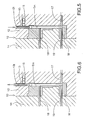
- FIG.5 is also a partial longitudinal sectional view of the casting machine of FIG.1, showing the condition where a separate member has been force-fitted into the casting;
- FIG.6 is also a partial longitudinal sectional view of the casting machine of FIG.1, showing the condition after the separate member has been force-fitted into the casting;
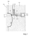
- FIG.7 is a partial longitudinal sectional view of the casting machine with a force-fitting mechanism according to a second embodiment of the invention;
- FIG.8 is also a partial longitudinal sectional view of the casting machine of FIG.7, showing the condition where the sliding member has been drawn out subsequently to solidification of the molten metal in the cavity;
- FIG.9(A) is also a partial longitudinal sectional view of the casting machine of FIG.7, showing the condition where the separate member has been force-fitted into the casting;
- FIG.9(B) illustrates in detail a pipe and an opening into which the pipe is to be force-fitted;
- FIG.10 is a partial longitudinal sectional view of the casting machine with a force-fitting mechanism according to a third embodiment of the invention;
- FIGS.11(A) and 11(B) are graphs of the changes in the force required for the force-fitting by the casting machine of FIG.7;
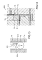
- FIG.12 is a partial longitudinal sectional view of a casting machine with a force-fitting mechanism according to a fourth embodiment of the invention;
- FIG.13 illustrates a distal end of a sliding member and a separate member of the casting machine of FIG.12;
- FIG.14(A) is a side view of the separate member and the sliding member of the casting machine of FIG.12 during the force-fitting step; and
- FIG.14(B) is a plan view of the separate member and the sliding member of the casting machine of FIG.12 during the force-fitting step.
-
- A casting machine with a force-fitting mechanism in accordance with a first embodiment of the present invention and a method carried out by the casting machine will be described with reference to FIGS.1 to 6.
- Referring to FIG.1, the casting machine with the force-fitting mechanism in accordance with the first embodiment is equipped with a
fixed metal mold 12 and amovable metal mold 14 both of which constitute a casting mold 9. The fixed andmovable molds cavity 16 is defined in the interior of the casting mold 9. - The fixed
mold 12 has apin guide passage 12t formed in an upper portion of the fixedmold 12 to extend vertically along an extension line from thecavity 16, as viewed in FIG.1. Acenter slide pin 13 for defining a main passage Tm (see FIG.4) of a casting W is slidably accommodated in thepin guide passage 12t. Thecenter slide pin 13 is connected at its upper end to an elevator mechanism (not shown) and has a lower distal end adapted to project a predetermined length out of thepin guide passage 12t into thecavity 16. - The fixed
mold 12 has aball passage 12s formed in the upper portion thereof to be perpendicular to thepin guide passage 12t, as viewed in FIG.1. A set ofballs 15 each serving as a closure member are accommodated in theball passage 12s. Theballs 15 are those used in a ball bearing, for example. A coil spring (not shown) is mounted to a right-hand end of theball passage 12s for urging theballs 15 accommodated in theball passage 12s toward thepin guide passage 12t. A cylinder, elastic member, magnet, etc. may be used instead of the coil spring. Furthermore, the self- weight of theballs 15 may be utilized for urging them toward thepin guide passage 12t. Each of theballs 15 serves as a separate member to be force-fitted into a casting, as will be described later. - The fixed
mold 12 has in its lower portion alateral pin passage 12y formed to be parallel to theball passage 12s, as viewed in FIG.1. Apressure pin 17 is slidably accommodated in thelateral pin passage 12y. Thepressure pin 17 is driven by a pressure cylinder (not shown) so that its distal end projects a predetermined length into thecavity 16 to thereby support the distal end of thecenter slide pin 13 positioned in thecavity 16. - First and
second draw pins movable mold 14 for defining first and second passages Th and Ts (see FIG.4) in the casting W respectively. Thefirst draw pin 18 horizontally projects into the upper interior of thecavity 16, abutting against the side surface of thecenter slide pin 13, as viewed in FIG.1. Thesecond draw pin 19 horizontally projects into the lower interior of thecavity 16, abutting against the distal end of thecenter slide pin 13 at the side opposite to thepressure pin 17. - The operation of the casting machine with the force- fitting mechanism will be described. The elevator mechanism (not shown) is first operated to lower the
center slide pin 13 so that the center slide pin projects into the cavity. In this state, the distal end of thepin 13 projects a predetermined length into thecavity 16. The pressure cylinder (not shown) is then operated so that thepressure pin 17 projects into thecavity 16, abutting at its distal end surface against the side surface of the distal end of thecenter slide pin 13. The mold clamping mechanism (not shown) is then operated to clamp the fixed andmovable molds second draw pins center slide pin 13. - Upon completion of the clamping of the
molds cavity 16 at high speed, as shown in FIG.2. While the molten metal is injected into thecavity 16, a lateral force is applied to thecenter slide pin 13 by the flow of the molten metal. When the cavity is filled with the molten metal, thecenter slide pin 13 is free from the lateral force. When thecenter slide pin 13 is free from the lateral force, apressure pin 17 is retreated (see FIG.3). Another predetermined amount of molten metal is supplemented between thecenter slide pin 13 and the retreatedpressure pin 17, as shown in FIG.3. The supplemented molten metal is supplied from outside thecavity 16. Thepressure pin 17 is re-advanced to apply pressure to the molten metal solidifying in thecavity 16 so that blowholes are crushed and the structure of the casting W is rendered sound. - The
center slide pin 13 is then moved upward to be thereby drawn out from the casting W when the molten metal in thecavity 16 is solidified with lapse of a predetermined time into such a degree as to maintain a certain shape. Consequently, the casting W is formed in the casting mold 9, as shown in FIG.4. The main passage Tm is formed in the casting W. - The elevator mechanism is operated to move the
center slide pin 13 upward so that its distal end is positioned higher than theball passage 12s. More specifically, theball passage 12s communicates with thepin guide passage 12t at a position between the distal end of the raisedcenter slide pin 13 and thecavity 16. The first ball of the row ofballs 15 in theball passage 12s is pushed into thepin guide passage 12t when the distal end of thecenter slide pin 13 is moved upward to a position higher than theball passage 12s (see FIG.4). - The
center slide pin 13 is lowered again from the above-described state so that theball 15 supplied into thepin guide passage 12t is force-fitted into an upper end of the main passage Tm by thecenter slide pin 13. As a result, the end of the main passage Tm is closed by thehall 15. Thus, the separate member or theball 15 is force-fitted into the concavity or the main passage Tm formed in the casting W while the casting W is enclosed in the casting mold 9. - The
center slide pin 13 is slightly moved upward to be drawn out from the casting W upon completion of the force-fitting of theball 15 into the main passage Tm, as shown in FIG.6. The distal end of thecenter slide pin 13 is held at a position lower than theball passage 12s such that an exit of theball passage 12s is closed by the side wall of thecenter slide pin 13. In this state, themolds - In accordance with the above-described first embodiment, the separate member is force-fitted into the casting W while the latter is enclosed in the casting mold 9. While the casting W is enclosed in the casting mold, the metal of the casting is not so hard and the metal condition is suitable for press-fitting. Accordingly, the end of the passage need not he machined as conventionally executed, the manufacturing cost of the product can he reduced, and the manufacturing process and time can be shortened. Furthermore, the force-fitting of the
separate member 15 is carried out before the casting W is taken out from themolds - Furthermore, since the
center slide pin 13 of the casting machine is used to force-fit theball 15 into the main passage Tm, no cylinder or pin dedicated to the force-fitting of theball 15 is provided. Consequently, complication in the construction of the casting machine can be prevented and the equipment cost for the casting can be reduced. Alternatively, a sliding member dedicated to the force-fitting may be provided at the side opposite to thecenter slide pin 13 when a through hole is formed in the casting W by the center slide pin. In this case, too, the force-fitting can be executed while the casting is enclosed in the casting mold. - A second embodiment of the invention will be described with reference to FIGS.7 to 9(B). As shown in FIG.7, a casting machine with a force-fitting mechanism of the second embodiment is equipped with a fixed
metal mold 112 and amovable metal mold 114. The fixed andmovable molds elongated cavity 116 serving as a product molding space is defined in the interior of the casting mold. - The fixed
mold 112 has a horizontally extendingpin guide passage 112t formed therein to be continuous substantially perpendicularly to the upper interior of thecavity 116. Thepin guide passage 112t is provided for guiding aslide pin 113 and has an inner diameter approximately equal to an outer diameter of theslide pin 113. Theslide pin 113 is provided for forming in a casting W an opening Wt into which a pipe P is to be force-fitted and for force-fitting the pipe P into the opening Wt. Theslide pin 113 is slidably accommodated in thepin guide passage 112t and connected at itsproximal end 113m to a pushingcylinder 123. - The fixed
mold 112 has arecess 112a formed in one side thereof. The pushingcylinder 123 is accommodated in therecess 112a to be positioned coaxial with theslide pin 113. The pushingcylinder 123 is operated for moving theslide pin 113 forward and backward along thepin guide passage 112t. FIG.7 shows the condition where theslide pin 113 is in its forward end position. - A
pipe passage 125 is continuous perpendicularly to a middle portion of thepin guide passage 112t. Thepipe passage 125 is provided for accommodating a plurality of pipes P therein in parallel with theslide pin 113. Thepipe passage 125 has a substantially equal transverse dimension to the length of each pipe P and a width substantially equal to the outer diameter of each pipe P. Accordingly, the pipes P are accommodated in thepipe passage 125 to be arranged in parallel to theslide pin 113. The outer diameter of each pipe P is set to be substantially equal to an outer diameter of theslide pin 113. - A coil spring (not shown) or the like is provided in the
pipe passage 125 for urging the pipes P toward thepin passage 112t. Accordingly, one pipe P is automatically supplied to thepin guide passage 112t when the distal end of theslide pin 113 is moved backward behind thepipe passage 125. A cylinder, elastic member, etc. may be used instead of the coil spring. Furthermore, the self-weight of the pipes P may be utilized for urging them toward thepin guide passage 112t. - The operation of the casting machine of the second embodiment will be described. With the
molds cylinder 123 is driven so that theslide pin 113 is held at the forward end position. As a result, an exit of thepipe passage 125 is closed by theslide pin 113, and the pipes P are held in parallel with theslide pin 113 in thepipe passage 125. The mold clamping mechanism (not shown) is then operated to clamp the fixed andmovable molds - Upon completion of the clamping of the
molds cavity 116 at high speed, as shown in FIG.7. When the molten metal in thecavity 116 is semi-solidified with lapse of a predetermined time or when the molten metal is solidified to such a degree as to maintain a certain shape, the pushingcylinder 123 is driven so that theslide pin 113 is pulled out from the semi-solidified molten metal, as shown in FIG.8. Consequently, the opening Wt is formed in the semi-solidified molten metal which will hereinafter be referred to as "casting W" and the exit of thepipe passage 125 is opened so that one pipe P is supplied from thepipe passage 125 to thepin guide passage 112t. - The pushing
cylinder 123 is driven again to move theslide pin 113 forward. The pipe P supplied to thepin guide passage 112t is then pushed by theslide pin 113 axially to be thereby force-fitted into the opening Wt of the casting W, as shown in FIG .9. The molten metal is completely solidified upon lapse of a predetermined time. Themolds cylinder 123 is driven to hold theslide pin 113 at the forward end position in preparation for the subsequent casting process. - In accordance with the above-described second embodiment, the pipe P is force-fitted into the opening Wt when the molten metal solidifies to such a degree as to maintain the certain shape in the
cavity 116. The pipe P can be prevented from being subjected to the molten metal charging pressure and can be force-fitted into the casting W by a relatively smaller force. Consequently, the deformation of the pipe P or the like can be prevented. Furthermore, since the molten metal is prevented from entering the inside of the pipe P, the pipe can reliably be fixed to the casting W only if the pipe has a thickness sufficient for the force-fitting. - Furthermore, a force-fitted portion Pi of the pipe P is cylindrical, whereas the
slide pin 113 is provided with a draft on its distal end. Consequently, the opening Wt formed by theslide pin 113 has a diameter smaller by a shaded portion S than the force-fitted portion Pi of the pipe P, as shown in FIG.9(B). When the pipe P is force-fitted into the opening Wt with the molten metal in the semi-solidified state, a radial pressure is applied to the shaded portion S by the pipe P such that the shaded portion S is squeezed. Consequently, the structure of the casting W is densified, and the degree of adhesion between the pipe P and the casting W can be improved. Furthermore, the degree of adhesion can further be improved by shrinkage due to solidification of the molten metal. Furthermore, the accuracy in machining the pipes P may be lower as compared with the prior art in which a pipe is force-fitted into a machined opening. Additionally, since the pipe P is force-fitted into the opening Wt before themolds molds - FIGS.10 and 11 illustrate a third embodiment of the invention. As shown in FIG.10, a
casting machine 200 of the third embodiment incorporates an improvement in the elevator mechanism for thecenter slide pin 13 of the castingmachine 10 in the above-described first embodiment. The other construction of thecasting machine 200 of the third embodiment is the same as that in the first embodiment. Accordingly, the identical parts are labeled by the same reference symbols in the third embodiment as in the first embodiment and the description of them will be eliminated. - A
center slide pin 213 of thecasting machine 200 is connected at its proximal end to apiston rod 221 of alift cylinder 220. Thelift cylinder 220 is mounted to the top of the fixedmold 12 to be coaxial with thecenter slide pin 213. Thelift cylinder 220 is operated to move thecenter slide pin 213 upward and downward along thepin guide passage 12t. Thelift cylinder 220 has upper and lowerhydraulic oil chambers hydraulic oil pipes hydraulic oil chambers hydraulic oil pipe 225p to the upperhydraulic oil chamber 225 so that thecenter slide pin 213 is lowered. The hydraulic oil is supplied through the secondhydraulic oil pipe 226p to the lowerhydraulic oil chamber 226 so that thecenter slide pin 213 is moved upward. - The first
hydraulic oil pipe 225p is provided with apressure sensor 230 for detecting pressure in the upperhydraulic oil chamber 225 and a flowrate control valve 235 for controlling the amount of the hydraulic oil supplied to the upperhydraulic oil chamber 225 per a unit time. Thepressure sensor 230 detects the pressure in the upperhydraulic oil chamber 225, thereby generating a pressure signal representative of the pressure in the upperhydraulic oil chamber 225. The pressure signals are continuously inputted to acomputer 240, which delivers a control signal so that thecontrol valve 235 is remote controlled on the basis of the control signal. - The operation of the casting machine will be described. Upon solidification of the molten metal, the hydraulic oil is supplied to the lower
hydraulic oil chamber 226 of thelift cylinder 220 so that thecenter slide pin 213 is moved upward to be thereby pulled out from the casting W. As a result, a longitudinal main passage Tm is formed in the casting W. Furthermore, one of theballs 15 in theball passage 12s is supplied into thepin guide passage 12t. The hydraulic oil is then supplied to the upperhydraulic oil chamber 225 of thelift cylinder 220 so that thecenter slide pin 213 is lowered. Theball 15 in thepin guide passage 12t is pushed by thecenter slide pin 213 into the main passage Tm, whereupon the force-fitting is initiated. - When the pressure in the upper
hydraulic oil chamber 225 detected by thepressure sensor 230 is at or above a predetermined value S, thecontrol valve 235 is opened to a predetermined extent of opening so that theball 15 is force-fitted into the main passage Tm at a predetermined speed. On the other hand, thecontrol valve 235 is throttled to reduce an amount of oil supplied to the upperhydraulic oil chamber 225 when the detected pressure in the upperhydraulic oil chamber 225 is below the predetermined value S, that is, when a force required for the force-fitting of theball 15 into the main passage Tm is small. Consequently, a lowering speed of thecenter slide pin 213 is reduced such that the force-fitting of theball 15 is performed extremely slowly. - The solidification of the casting W is incomplete when the force required for the force-fitting is small. In this case, the speed of the force-fitting is reduced and the solidification of the casting progresses. As the solidification progresses, the force required for the force-fitting is increased. When the force required for the force- fitting is increased to or above the predetermined value S with the progress of solidification of the casting W, the
control valve 235 is opened to the predetermined extent of opening so that theball 15 is force-fitted into the main passage Tm at the predetermined speed. - Graph F in each of FIGS.11(A) and 11(B) represents an oil pressure (force-fitting pressure) in the upper
hydraulic oil chamber 225 when the force-fitting is executed in accordance with the above-described method. Graphs T1, T2, T3 and T4 of FIG.11(A) represent force-fitting pressures when the force-fitting timing is uniformly set by a timer. The force-fitting pressure varies among the graphs T1-T4. The variations in the force-fitting pressure are considered to result from the differences in the progress of solidification of the molten metal under the influence of the temperatures of themetal molds - According to the third embodiment, however, the
center slide pin 213 is slowly operated when the force-fitting pressure is small. The force-fitting is executed at the predetermined speed when the force-fitting pressure (force-fitting reactive force) has been increased to the predetermined value S. Consequently, since an amount of hydraulic oil supplied to the upperhydraulic chamber 225 is varied on the basis of the signals from thepressure sensor 230, the force-fitting can stably be executed with an optimum fitting force being applied to theball 15 even when the progress of solidification of the molten metal differs under the influence of the temperatures of themetal molds - Graph E of FIG.11(B) shows the changes in the force-fitting pressure when the
ball 15 has not been supplied from theball passage 12s to thepin guide passage 12t. In this case, the force-fitting pressure (force-fitting reactive force) is not increased to the predetermined value S and accordingly thecenter slide pin 213 is slowly operated. This results in a prompt determination of abnormal force-fitting. Furthermore, the determination of abnormal force-fitting can readily be made when a pressure waveform in the force-fitting is compared with the one in a normal force-fitting. - FIGS.12 to 14(B) illustrate a fourth embodiment of the invention. As shown in FIG.12, a
casting machine 300 of the fourth embodiment incorporates an improvement in the configuration of the distal end of thecenter slide pin 13 of the castingmachine 10 in the above-described first embodiment. The other construction of thecasting machine 300 is the same as that in the first embodiment. Accordingly, the identical parts are labeled by the same reference symbols in the fourth embodiment as in the first embodiment and the description of them will be eliminated. - The
center slide pin 313 of thecasting machine 300 has in its distal end aspherical depression 313r eccentric to the axis thereof, as shown in FIG.13. Thespherical depression 313r has a radius of curvature slightly larger than the radius of theball 15 serving as the separate member to be force-fitted. - The
center slide pin 313 is lowered to force-fit theball 15 into the casting W. Theball 15 is pushed by a boundary between thespherical depression 313r and adistal end surface 313f of thecenter slide pin 313, as shown in FIG.13, until theball 15 is guided into the main passage Tm of the casting W. However, after having come into contact with the inner wall surface of the main passage Tm, theball 15 is advanced inward, elastically deforming the inner wall surface of the main passage Tm. This movement of theball 15 results in a reactive force R, which axially acts at a position offset from the axis of thecenter slide pin 313. - Upon occurrence of the reactive force R, the
center slide pin 313 is elastically deformed by the reactive force R and the pushing force F thereof in its bending direction, whereupon thespherical depression 313r is located on the surface of theball 15, as shown in FIGS.14(A) and 14(B). More specifically, thecenter slide pin 313 is displaced such that the axis thereof is deviated from the center of theball 15. As a result, a part of thedistal end surface 313f of thepin 313 is forced out to the inner wall surface side of the main passage Tm. Thecenter slide pin 313 is further lowered under this condition such that theball 15 is pushed by thespherical depression 313r thereof and the inner wall surface of the main passage Tm is deformed by the forced-out part of thecenter slide pin 313. Consequently, the inner wall surface of the main passage Tm is plastically deformed to be inwardly protuberant, and theball 15 is force-fitted into the main passage Tm and simultaneously caulked, as shown in FIGS.14(A) and 14(B). Since the eccentricity of thecenter slide pin 313 relative to theball 15 results from the elastic deformation of the former, there is no problem for a continuous use of thecenter slide pin 313. - According to the fourth embodiment, the
ball 15 is force-fitted into the main passage Tm with the inner wall of the passage being deformed by thecenter slide pin 313. Theball 15 is caulked by the deformation of the main passage Tm. Consequently, theball 15 can reliably fixed in the main passage Tm of the casting W. - The foregoing description and drawings are merely illustrative of the principles of the present invention and are not to be construed in a limiting sense. Various changes and modifications will become apparent to those of ordinary skill in the art. All such changes and modifications are seen to fall within the true spirit and scope of the invention as defined by the appended claims.
- A cavity defined by a casting mold is filled with a molten metal in such a condition that a sliding member movable forward and rearward has been moved into the cavity. The sliding member is drawn out of the cavity when the molten metal solidifies to such a degree as to maintain a certain shape. A separate member to be force-fitted is placed between the distal end of the sliding member and the cavity. The sliding member is then advanced into the cavity so that the separate member is force-fitted into a concave portion formed in the casting before the casting mold enclosing the casting is opened. The separate member is thus force-fitted into the casting while the casting is enclosed in the casting mold.
Claims (12)
- A method of force-fitting a separate member (15, P) into a casting (W), comprising the steps of:filling a cavity (16, 116) defined by a casting mold (12, 14, 112, 114) with a molten metal in such a condition that a sliding member (13, 113) movable forward and rearward has been moved into the cavity;with drawing the sliding member (13, 113, 213, 313) from the cavity (16, 116) when the molten metal is solidified to such a degree as to maintain a certain shape; andforce-fitting the separate member (15, P) into a passage (Tm, Wt) formed in the casting (W) by means of the sliding member (13, 113, 213, 313) before the casting mold is opened.
- A method according to claim 1, wherein the separate member is a ball (15) and closes the passage (Tm) when force-fitted thereinto.
- A method according to claim 1, wherein the separate member is a pipe (P) and communicates with the passage (Wt) when force-fitted thereinto.
- A method according to claim 1, wherein the force-fitting step includes the additional step of detecting a magnitude of a force required for the force-fitting so that a force-fitting speed is reduced when the detected magnitude is below a predetermined value and so that the force-fitting speed is set at a predetermined one when the detected magnitude is at or above the predetermined value.
- A method according to claim 1, wherein an end of the passage (Tm, Wt) in which the separate member (15, P) has been force-fitted is caulked during the force-fitting step.
- A method according to claim 1, wherein the force-fitting step includes the steps of:placing the separate member (15, P) between a distal end of the sliding member (13, 113, 213, 313) withdrawn and the cavity (16, 116); andmoving the sliding member (13, 113, 213, 313) forward so that the separate member (15, P) is force-fitted into the passage (Tm, Wt) formed in the casting (W) by the sliding member before the casting mold (12, 14, 112, 114) is opened.
- A method according to claims 1 to 6, wherein the distal end (313r, 313f) of the sliding member (313) deforms a wall defining the passage (Tm) in the force-fitting step.
- An apparatus for force-fitting a separate member (15, P) into a casting (W), comprising:a casting mold (12, 14, 112, 114) having a cavity (16, 116) defined therein;a sliding member (13, 113, 213, 313) movable between a first position at which the same has been moved into the cavity a second position at which the same has been withdrawn from the cavity, the sliding member defining a passage (Tm, Wt) in the casting (W), andmeans (123, 220) for force-fitting the separate member (15, P) into the passage (Tm, Wt) formed in the casting (W) when the sliding member is withdrawn, before the casting mold is opened.
- An apparatus according to claim 8, comprising:a guide passage (12t, 112t) leading to the cavity for guiding the sliding member (13, 113, 213, 313);means (12s, 125) for supplying the separate member (15, P) to a location in the guide passage (12t, 112t) between the cavity (16, 116) and a distal end of the sliding member (13, 113, 213, 313) at the second position; andmeans (123, 220) for re-advancing the sliding member.
- An apparatus according to claim 9, wherein the supplying means has a passage (12s, 125) along which the separate member (15, P) passes and which communicates with the guide passage (12t, 112t) at a location between the cavity (16, 116) and the distal end of the sliding member (13, 113, 213, 313) at the second position.
- An apparatus according to claim 9, wherein the re-advancing means (220) includes a detector (230) for detecting a force required for advancing the sliding member (213) and speed adjusting means (235) for reducing a force-fitting speed when the detected force is below a predetermined value and setting the force-fitting speed at a predetermined one when the detected force is at or above the predetermined value.
- An apparatus according to claim 9, wherein the sliding member (313) has such a configuration (313r, 313f) as to abut against the separate member (15) at a position displaced from an axis thereof and is subjected to an axial force at the displaced position, thereby flexing in a direction approximately perpendicular to the axis.
Applications Claiming Priority (6)
| Application Number | Priority Date | Filing Date | Title |
|---|---|---|---|
| JP163323/96 | 1996-06-24 | ||
| JP16332396 | 1996-06-24 | ||
| JP16332396 | 1996-06-24 | ||
| JP337216/96 | 1996-12-17 | ||
| JP33721696 | 1996-12-17 | ||
| JP33721696A JP3668823B2 (en) | 1995-12-19 | 1996-12-17 | Method and apparatus for press-fitting another member into a casting passage |
Publications (2)
| Publication Number | Publication Date |
|---|---|
| EP0815988A1 EP0815988A1 (en) | 1998-01-07 |
| EP0815988B1 true EP0815988B1 (en) | 2000-09-06 |
Family
ID=26488794
Family Applications (1)
| Application Number | Title | Priority Date | Filing Date |
|---|---|---|---|
| EP97108798A Expired - Lifetime EP0815988B1 (en) | 1996-06-24 | 1997-06-02 | Method of force-fitting separate member into casting and apparatus therefor |
Country Status (3)
| Country | Link |
|---|---|
| US (1) | US5960852A (en) |
| EP (1) | EP0815988B1 (en) |
| DE (1) | DE69703008T2 (en) |
Family Cites Families (7)
| Publication number | Priority date | Publication date | Assignee | Title |
|---|---|---|---|---|
| DE1086862B (en) * | 1951-10-24 | 1960-08-11 | Frigast & Co E | Process for regulating the flame length of spray nozzle bodies for liquid spray burners manufactured by injection molding |
| DE1577099A1 (en) * | 1966-10-01 | 1970-03-12 | Mahle Kg | Method for producing a light metal piston with a closed ring channel arranged in its head part |
| US3952395A (en) * | 1974-12-30 | 1976-04-27 | Goodyear Aerospace Corporation | Method of closing the end of a drilled passage |
| DE2838773C2 (en) * | 1978-09-06 | 1983-02-10 | Licentia Patent-Verwaltungs-Gmbh, 6000 Frankfurt | Method of manufacturing the needle-side part of needle roller bearings for electricity meters |
| JPS55149763A (en) * | 1979-05-11 | 1980-11-21 | Yamada Seisakusho:Kk | Die casting method to perform press working and internal chill of insert pipe simultaneously |
| JPS611461A (en) * | 1984-06-13 | 1986-01-07 | Taiho Kogyo Co Ltd | Casting method |
| JPH01241369A (en) * | 1988-03-18 | 1989-09-26 | Tokai Rika Co Ltd | Casting method |
-
1997
- 1997-06-02 DE DE69703008T patent/DE69703008T2/en not_active Expired - Fee Related
- 1997-06-02 EP EP97108798A patent/EP0815988B1/en not_active Expired - Lifetime
- 1997-06-03 US US08/868,153 patent/US5960852A/en not_active Expired - Fee Related
Also Published As
| Publication number | Publication date |
|---|---|
| EP0815988A1 (en) | 1998-01-07 |
| US5960852A (en) | 1999-10-05 |
| DE69703008D1 (en) | 2000-10-12 |
| DE69703008T2 (en) | 2001-05-10 |
Similar Documents
| Publication | Publication Date | Title |
|---|---|---|
| CN100575902C (en) | Molding machine capable of stably detecting abnormality of extruded pins and abnormality detection method | |
| JP3233358B2 (en) | How to insert a pipe | |
| EP0697263A1 (en) | Pressure casting method through pressurizing pin advancement speed control | |
| US4874032A (en) | Die casting controlling method | |
| US20020011323A1 (en) | Apparatus and method of forming battery parts | |
| US6202733B1 (en) | Apparatus and method of forming battery parts | |
| US20040256073A1 (en) | Die casting machine and casting method | |
| US5960852A (en) | Method of force-fitting separate member into casting and apparatus therefor | |
| JP3981832B2 (en) | Cylinder block casting method | |
| JP5265219B2 (en) | Insert molding method | |
| US5711364A (en) | Method of and apparatus for casting pipe | |
| US4846252A (en) | Secondary pressurization casting method | |
| US7210514B2 (en) | Die casting machine | |
| CN110548854B (en) | Forging control method for metal product | |
| US6684935B2 (en) | Intensification through displacement of a coacting mold member | |
| JP3668823B2 (en) | Method and apparatus for press-fitting another member into a casting passage | |
| JPH04123854A (en) | Method for inserting pipe body as cast-in | |
| EP0993891B1 (en) | Pressure casting of battery terminals | |
| JPH09103861A (en) | Plunger chip cooling method and device for die casting machine | |
| JPH0810930A (en) | Pressure casting equipment | |
| JPH05253658A (en) | Casting apparatus and casting method for die casting | |
| JPH0783920B2 (en) | Casting pin drawing method for casting equipment | |
| JPH08309503A (en) | Pressure casting method | |
| JPH0531564A (en) | Method for controlling pressurized timing for squeeze pin in partial squeeze casting | |
| JP2000084970A (en) | Molding method and molding die for long shaft parts |
Legal Events
| Date | Code | Title | Description |
|---|---|---|---|
| PUAI | Public reference made under article 153(3) epc to a published international application that has entered the european phase |
Free format text: ORIGINAL CODE: 0009012 |
|
| 17P | Request for examination filed |
Effective date: 19970701 |
|
| AK | Designated contracting states |
Kind code of ref document: A1 Designated state(s): DE FR IT |
|
| AKX | Designation fees paid |
Free format text: DE FR IT |
|
| RBV | Designated contracting states (corrected) |
Designated state(s): DE FR IT |
|
| 17Q | First examination report despatched |
Effective date: 19981002 |
|
| GRAG | Despatch of communication of intention to grant |
Free format text: ORIGINAL CODE: EPIDOS AGRA |
|
| GRAG | Despatch of communication of intention to grant |
Free format text: ORIGINAL CODE: EPIDOS AGRA |
|
| GRAH | Despatch of communication of intention to grant a patent |
Free format text: ORIGINAL CODE: EPIDOS IGRA |
|
| GRAH | Despatch of communication of intention to grant a patent |
Free format text: ORIGINAL CODE: EPIDOS IGRA |
|
| GRAA | (expected) grant |
Free format text: ORIGINAL CODE: 0009210 |
|
| AK | Designated contracting states |
Kind code of ref document: B1 Designated state(s): DE FR IT |
|
| REF | Corresponds to: |
Ref document number: 69703008 Country of ref document: DE Date of ref document: 20001012 |
|
| ET | Fr: translation filed | ||
| ITF | It: translation for a ep patent filed | ||
| PLBE | No opposition filed within time limit |
Free format text: ORIGINAL CODE: 0009261 |
|
| STAA | Information on the status of an ep patent application or granted ep patent |
Free format text: STATUS: NO OPPOSITION FILED WITHIN TIME LIMIT |
|
| 26N | No opposition filed | ||
| PGFP | Annual fee paid to national office [announced via postgrant information from national office to epo] |
Ref country code: DE Payment date: 20060525 Year of fee payment: 10 |
|
| PGFP | Annual fee paid to national office [announced via postgrant information from national office to epo] |
Ref country code: FR Payment date: 20060608 Year of fee payment: 10 |
|
| PGFP | Annual fee paid to national office [announced via postgrant information from national office to epo] |
Ref country code: IT Payment date: 20060630 Year of fee payment: 10 |
|
| REG | Reference to a national code |
Ref country code: FR Ref legal event code: ST Effective date: 20080229 |
|
| PG25 | Lapsed in a contracting state [announced via postgrant information from national office to epo] |
Ref country code: DE Free format text: LAPSE BECAUSE OF NON-PAYMENT OF DUE FEES Effective date: 20080101 |
|
| PG25 | Lapsed in a contracting state [announced via postgrant information from national office to epo] |
Ref country code: FR Free format text: LAPSE BECAUSE OF NON-PAYMENT OF DUE FEES Effective date: 20070702 |
|
| PG25 | Lapsed in a contracting state [announced via postgrant information from national office to epo] |
Ref country code: IT Free format text: LAPSE BECAUSE OF NON-PAYMENT OF DUE FEES Effective date: 20070602 |