EP0814635B1 - Hearing aid - Google Patents
Hearing aid Download PDFInfo
- Publication number
- EP0814635B1 EP0814635B1 EP96110068A EP96110068A EP0814635B1 EP 0814635 B1 EP0814635 B1 EP 0814635B1 EP 96110068 A EP96110068 A EP 96110068A EP 96110068 A EP96110068 A EP 96110068A EP 0814635 B1 EP0814635 B1 EP 0814635B1
- Authority
- EP
- European Patent Office
- Prior art keywords
- signal
- hearing aid
- amplifier
- output
- calculating means
- Prior art date
- Legal status (The legal status is an assumption and is not a legal conclusion. Google has not performed a legal analysis and makes no representation as to the accuracy of the status listed.)
- Revoked
Links
Images


Classifications
-
- H—ELECTRICITY
- H04—ELECTRIC COMMUNICATION TECHNIQUE
- H04R—LOUDSPEAKERS, MICROPHONES, GRAMOPHONE PICK-UPS OR LIKE ACOUSTIC ELECTROMECHANICAL TRANSDUCERS; DEAF-AID SETS; PUBLIC ADDRESS SYSTEMS
- H04R25/00—Deaf-aid sets, i.e. electro-acoustic or electro-mechanical hearing aids; Electric tinnitus maskers providing an auditory perception
- H04R25/50—Customised settings for obtaining desired overall acoustical characteristics
- H04R25/505—Customised settings for obtaining desired overall acoustical characteristics using digital signal processing
- H04R25/507—Customised settings for obtaining desired overall acoustical characteristics using digital signal processing implemented by neural network or fuzzy logic
Definitions
- the invention relates to a hearing aid according to the preamble of Claim 1.
- a signal here is the course one or more physical quantities on one or several measuring points can be understood over time; each Signal can therefore consist of a bundle of individual signals.
- Such a hearing device is known from EP-A-0 674 464, in which a fuzzy logic controller is provided to either the signal transmission characteristic of an amplifier and Change transmission device or set of parameters influencing the signal transmission characteristic to be selected automatically from a parameter memory.
- EP-A-0 674 463 discloses a similar hearing aid an automatic gain control circuit (automatic gain control - AGC) assigned a fuzzy logic controller is.
- the invention accordingly has the object of the problem mentioned to solve.
- the invention is intended to be a hearing aid be provided, which is with little developmental and Circuit effort can be made and an optimal Adaptation to the specific requirements of the hearing aid wearer allows.
- this object is achieved by a hearing aid with the features according to claim 1.
- a digital structure of a computing device, the fuzzy logic functions realized, offers a high degree of compatibility with digital signal processing: one additional implementation (analog / digital or digital / analog) is not required and the calculation device can completely or partially realized with the same components become like the rest of the processing of the signals. It follows the calculation device is easy to combine with conventional digital data and signal processing functions, such as in microprocessors or signal processors are common. In addition, digital technology offers Benefits such as increased immunity to interference and insensitivity against manufacturing tolerances.
- the calculation device is preferably with conventional digital ones Components such as gates, flip-flops, memories, etc. educated; more generally with switching networks and switching mechanisms. she can be used in particular as an ASIC (application specific integrated circuit - application-specific integrated circuit) his. Alternatively, it is possible to use the calculation device as a microprocessor or microcontroller with one train associated program in a read-only memory (ROM; especially mask-programmed ROM, PROM, EPROM or EEPROM) or a read-write memory (RAM) is saved. Mixed forms are also possible; for example can use specific hardwired modules with a programmed control. This is particularly so useful for functions that are performed frequently and can be realized digitally relatively easily, for example for functions for calculating the maximum or minimums of several binary numbers.
- the computing device is preferred in the hearing device according to the invention for direct signal processing and / or for the control of signal processing functions and / or for the automatic selection of hearing programs in the Hearing aid used.
- the computing device of the hearing aid realizes the fuzzy logic functions are preferred by executing the Sub-steps fuzzification of sharp input variables, Evaluation of premises, evaluation of partial conclusions, Accumulation of initial terms and defuzzification.
- the calculations required for this are preferably based on several Calculation modules distributed, the local or shared storage can have.
- Configuration parameters of the calculation device are preferred in a memory, for example a RAM or EEPROM, filed, so that reprogramming of the calculation device by the hearing care professional and / or even an adaptation of the function of the computing device during operation of the hearing aid is possible.
- a memory for example a RAM or EEPROM
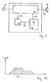
- a microphone acting as an input converter 12 produces a sound signal into an electrical signal and guides it an amplifier and transmission circuit 10 further.
- the Amplifier and transmission circuit 10 amplifies the incoming Signal and processes it, for example through selective Raising or weakening certain frequency or Volume areas.
- the output signal 28 processed in this way is output by a handset serving as an output transducer 14.
- At least one suitable point of the amplifier and Transmission circuit 10 is a tap signal 22 from the Tapped signal path of the hearing aid and a signal processing device 16 fed.
- the tap signal 22 can furthermore have individual signals which are transmitted by further input converters, of controls or sensors for Monitoring system properties (e.g. the Battery voltage).
- the signal conditioning device 16 prepares the tap signal 22 suitable, for example by rectification, Averaging or derivative over time to make it one Computing device 20, which realizes fuzzy logic functions, to supply as input signal 24.
- the content of EP-A-0 674 464 hereby expressly included in the present description.
- the calculation device 20 has a memory 18, the intermediate results and, if necessary, configuration parameters the calculation device 20 stores.
- the calculation device 20 processes the input signal supplied to it 24 in the manner described in more detail below the principles of fuzzy logic and gives the result as Result signal 26 to the amplifier and transmission device 10, their gain and transmission properties by the result signal acting as a control signal 26 can be changed within wide limits.
- Hearing aid controls the result signal 26 the transmission characteristic the amplifier and transmission device 10 directly by the individual signals of the Result signal 26 individual parameters of the amplifier and Transmission device 10, for example the gain certain frequency bands or response and fall times an automatic gain control control - AGC).
- the amplifier and Transfer device 10 has a memory that several contains preset or programmed parameter sets.
- a parameter set of this memory is based on the result signal 26, selected, for example, that the digital result signal 26 as a memory address serves.
- the amplifier and transmission device 10 no immediate Signal path from input converter 12 to output converter 14 on. Rather, the signal path runs from the input converter 12 via a first part of the amplifier and transmission device 10 to the signal conditioning device 16, from there to the calculation device 20, from there as a result signal 26 to a second part of the amplifier and transmission device 10 and from there as an output signal 28 to Output converter 14. In the second part of the amplifier and Transmission device 10 becomes the digital result signal 26 only converted into an analog signal and possibly filtered.
- the expression between IF and THEN is called the premise; the expression to the right of the THEN is called a conclusion designated.
- the sub-expressions in parentheses become corresponding referred to as partial premises and partial conclusions.
- the calculation device 20 serves the structure shown in FIG. 2 only for the conceptual representation of a fuzzy logic calculation, because in actual implementation one arbitrary assignment of the partial functions shown in FIG. 2 to one or more modules of the calculation device 20 can be done.
- Step 1) Fuzzification of the input variables
- Fuzzification determines the value of a membership function of every linguistic term of corresponding linguistic variables in the current Value of the input variable.
- the example set of rules contains two linguistic variables A and B, each with two linguistic terms, namely (A is small), (A is large) and (B is small), (B is large).
- the graphs shown in FIG. 3 represent the membership functions of these terms: ⁇ small (A), ⁇ large (A) and ⁇ small (B), ⁇ large (B).
- Affiliation function is used to determine the degree of fulfillment by reading out the corresponding x value assigned y value from the memory.
- a negated variable occurs in the set of rules, it is Value of the inverse membership function according to the above to determine the specified formula. You can choose at the Calculate the values given in square brackets above be used.
- Step 2) Evaluation of the premises
- the values of the membership functions calculated in step 1) which is the degree of fulfillment of the partial premises (A large), (B is large) and so on, are in the example set of rules used here by linguistic ANDund OR operators on the premises of the individual rules connected.
- the calculation of the AND and OR operations of the partial premises is preferably done by calculating the Minimum or maximum of the corresponding degree of fulfillment, as shown in FIG. 6.
- the result of this Operation is the degree of fulfillment of the respective premise [(A is large) AND (B is large)], [(A is large) OR (B is large)] and so on. This calculation is done for all the rules.
- the first Partial step determines the degree of activation of the partial conclusion. The principle applies that every partial conclusion in is activated to the extent assigned to it in the set of rules Premises are fulfilled.
- the sharp initial value x is calculated as the mean value of the positions of the maxima of f active (X).
- the area over which integration or summation is carried out is preferably limited to the interval between X min and X max ; the interval between the smallest and the largest X value, for which f active (X)> 0 applies. This information arises when the starting terms are accumulated.
- mapping functions the degree of activation of the conclusion is mapped on the one hand to the activated area F n of the starting term, and on the other hand it is centered on a position S n this activated surface imaged. Both mapping rules do not have to be evaluated at runtime of the system, since they are only dependent on the starting terms and the method of converting the degree of activation of the conclusion into the activation of the terms (maximum formation or multiplication) shown in FIG. 8.
- This calculation method implicitly includes accumulation the terms by the method of addition.
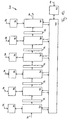
- the 12 is a first embodiment of the invention Calculator 20 shown, which described Executes fuzzy logic functions.
- the calculation device 20 has six calculation modules 30, which are connected in series via five buffers 32 are.
- Each calculation module 30 is also one Memory module 34 each assigned a configuration input 36.
- a control module 40 is with all calculation modules 30 and connected to a working memory 42 on which can be accessed externally via a connection 44.
- Each partial function type 50, 52, 54 shown in FIG. 56, 58 and 60 corresponds to one of the calculation modules 30 first calculation module 30 receives the sharp input values as input signal 24; the last calculation module 30 there the calculated sharp result values as result signal 26 out. The transfer of the intermediate results between the calculation modules 30 takes place via the buffer 32.
- each Memory module 34 may also contain configuration information for that executed by the respective calculation module 30 Partial function included. Such configuration information can, for example, in the first calculation module 30 receives the input signal 24, the membership functions of the Be input variables. To configure the fuzzy logic functions of the calculation device 20 are the memory modules 34 writable from the outside via the configuration inputs 36.
- the control module 40 coordinates the overall process and the cooperation of the calculation modules 30. For example the processing time in the individual calculation modules 30 be different. It is the task of the control module 40 then to notify each calculation module 30 if the intermediate results of the previous calculation module 30 for Pending further processing.
- calculation modules 30 and others Components of the computing device 20 in digital Circuit technology results directly in a known manner from the description of the corresponding sub-functions. she can be done by switching networks, switching mechanisms or a combination happen from both. Their exact function can be determined by configuration information be determined.
- Computation modules 30 do not necessarily need six his. There may be more or fewer calculation modules 30 be to calculate the fuzzy logic functions to divide finer or coarser. For example five calculation modules 30 corresponding to those described above Steps 1) to 5) can be used, or only a single one Calculation module 30 'as shown in FIG. 14 is.
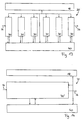
- FIG. 13 shows an embodiment variant of the calculation device 20. All buffers shown in Fig. 12 32 and memory modules 34 and the working memory 42 summarized here to the single memory 18. This allows a more rational use of storage space because it is partitioned as desired and according to the individual modules Can be assigned to demand. So information, which are required by different modules, only once are stored in the memory 18.
- the calculation modules 30 (or the calculation module 30 ') access on a preferably hard-wired module for determination the minimum minimum and / or the maximum of two or more Binary numbers. This is advantageous because the formation of the Minimum and maximum two in many fuzzy logic subfunctions occurring basic functions are.
Abstract
Description
Die Erfindung betrifft ein Hörgerät nach dem Oberbegriff des
Anspruchs 1. Unter einem "Signal" soll hier der Verlauf
einer oder mehrerer physikalischer Größen an einem oder
mehreren Meßpunkten über die Zeit verstanden werden; jedes
Signal kann also aus einem Bündel von Einzelsignalen bestehen.The invention relates to a hearing aid according to the preamble of
Aus der EP-A-0 674 464 ist ein derartiges Hörgerät bekannt, bei dem ein Fuzzy-Logik-Controller vorgesehen ist, um entweder die Signalübertragungscharakteristik einer Verstärkerund Übertragungseinrichtung zu verändern oder einen Satz von die Signalübertragungscharakteristik beeinflussenden Parametern aus einem Parameterspeicher automatisch auszuwählen.Such a hearing device is known from EP-A-0 674 464, in which a fuzzy logic controller is provided to either the signal transmission characteristic of an amplifier and Change transmission device or set of parameters influencing the signal transmission characteristic to be selected automatically from a parameter memory.
In der EP-A-0 674 463 ist ein ähnliches Hörgerät offenbart, bei dem einer automatischen Verstärkungsregelschaltung (automatic gain control - AGC) ein Fuzzy-Logik-Regler zugeordnet ist.EP-A-0 674 463 discloses a similar hearing aid an automatic gain control circuit (automatic gain control - AGC) assigned a fuzzy logic controller is.
Bei den in diesen Offenlegungsschriften beschriebenen Hörgeräten ist jedoch nur eine Realisierung von Fuzzy-Logik-Funktionen in analoger Schaltungstechnik vorgesehen. Daraus ergibt sich das Problem eines hohen schaltungstechnischen Aufwandes, der insbesondere wegen der bei Hörgeräten erforderlichen Miniaturisierung nachteilig ins Gewicht fällt.In the hearing aids described in these published documents is however only an implementation of fuzzy logic functions provided in analog circuit technology. It follows the problem of high circuit complexity, the particular because of the necessary with hearing aids Miniaturization is a disadvantage.
Die Erfindung hat demgemäß die Aufgabe, das genannte Problem zu lösen. Insbesondere soll durch die Erfindung ein Hörgerät bereitgestellt werden, das sich mit geringem Entwicklungsund Schaltungsaufwand herstellen läßt und dabei eine optimale Anpassung an die spezifischen Erfordernisse des Hörgeräteträgers ermöglicht. The invention accordingly has the object of the problem mentioned to solve. In particular, the invention is intended to be a hearing aid be provided, which is with little developmental and Circuit effort can be made and an optimal Adaptation to the specific requirements of the hearing aid wearer allows.
Erfindungsgemäß wird diese Aufgabe gelöst durch ein Hörgerät
mit den Merkmalen gemäß Patentanspruch 1.According to the invention, this object is achieved by a hearing aid
with the features according to
Ein digitaler Aufbau einer Berechnungseinrichtung, die Fuzzy-Logik-Funktionen realisiert, bietet ein hohes Maß an Kompatibilität mit der digitalen Signalverarbeitung: Eine zusätzliche Umsetzung (Analog/Digital oder Digital/Analog) ist nicht erforderlich, und die Berechnungseinrichtung kann ganz oder teilweise mit den gleichen Komponenten realisiert werden wie die übrige Verarbeitung der Signale. Daraus ergibt sich eine leichte Kombinierbarkeit der Berechnungseinrichtung mit herkömmlichen digitalen Daten- und Signalverarbeitungsfunktionen, wie sie z.B. in Mikroprozessoren oder Signalprozessoren üblich sind. Überdies bietet die Digitaltechnik Vorzüge wie erhöhte Störsicherheit und Unempfindlichkeit gegen Fertigungstoleranzen.A digital structure of a computing device, the fuzzy logic functions realized, offers a high degree of compatibility with digital signal processing: one additional implementation (analog / digital or digital / analog) is not required and the calculation device can completely or partially realized with the same components become like the rest of the processing of the signals. It follows the calculation device is easy to combine with conventional digital data and signal processing functions, such as in microprocessors or signal processors are common. In addition, digital technology offers Benefits such as increased immunity to interference and insensitivity against manufacturing tolerances.
Die Berechnungseinrichtung ist bevorzugt mit üblichen digitalen Bauelementen wie Gattern, Flip-Flops, Speichern etc. gebildet; allgemeiner mit Schaltnetzen und Schaltwerken. Sie kann insbesondere als ASIC (application specific integrated circuit - anwendungsspezifische integrierte Schaltung) ausgestaltet sein. Alternativ ist es möglich, die Berechnungseinrichtung als Mikroprozessor oder Mikrocontroller mit einem zugehörigen Programm auszubilden, das in einem Nur-Lese-Speicher (ROM; insbesondere maskenprogrammiertes ROM, PROM, EPROM oder EEPROM) oder einem Schreib-Lese-Speicher (RAM) gespeichert ist. Auch Mischformen sind möglich; beispielsweise können spezifische festverdrahtete Module mit einer programmierten Steuerung verbunden sein. Dies ist insbesondere für Funktionen sinnvoll, die häufig ausgeführt werden und sich relativ einfach digital realisieren lassen, beispielsweise für Funktionen zur Berechnung des Maximums oder Minimums mehrerer Binärzahlen.The calculation device is preferably with conventional digital ones Components such as gates, flip-flops, memories, etc. educated; more generally with switching networks and switching mechanisms. she can be used in particular as an ASIC (application specific integrated circuit - application-specific integrated circuit) his. Alternatively, it is possible to use the calculation device as a microprocessor or microcontroller with one train associated program in a read-only memory (ROM; especially mask-programmed ROM, PROM, EPROM or EEPROM) or a read-write memory (RAM) is saved. Mixed forms are also possible; for example can use specific hardwired modules with a programmed control. This is particularly so useful for functions that are performed frequently and can be realized digitally relatively easily, for example for functions for calculating the maximum or minimums of several binary numbers.
Bevorzugt wird bei dem erfindungsgemäßen Hörgerät die Berechnungseinrichtung für die direkte Signalverarbeitung und/oder für die Steuerung von Signalverarbeitungsfunktionen und/oder für die automatische Auswahl von Hörprogrammen im Hörgerät eingesetzt.The computing device is preferred in the hearing device according to the invention for direct signal processing and / or for the control of signal processing functions and / or for the automatic selection of hearing programs in the Hearing aid used.
Ferner realisiert die Berechnungseinrichtung des Hörgerätes die Fuzzy-Logik-Funktionen bevorzugt durch Ausführen der Teilschritte Fuzzyfizierung von scharfen Eingangsvariablen, Auswertung von Prämissen, Auswertung von Teilkonklusionen, Akkumulation von Ausgangstermen und Defuzzyfizierung. Die dazu erforderlichen Berechnungen sind bevorzugt auf mehrere Berechnungsmodule verteilt, die lokale oder gemeinsame Speicher aufweisen können.Furthermore, the computing device of the hearing aid realizes the fuzzy logic functions are preferred by executing the Sub-steps fuzzification of sharp input variables, Evaluation of premises, evaluation of partial conclusions, Accumulation of initial terms and defuzzification. The calculations required for this are preferably based on several Calculation modules distributed, the local or shared storage can have.
Konfigurationsparameter der Berechnungseinrichtung sind vorzugsweise in einem Speicher, beispielsweise einem RAM oder EEPROM, abgelegt, so daß eine Neuprogrammierung der Berechnungseinrichtung durch den Hörgeräteakustiker und/oder sogar eine Adaption der Funktion der Berechnungseinrichtung während des Betriebs des Hörgerätes möglich ist.Configuration parameters of the calculation device are preferred in a memory, for example a RAM or EEPROM, filed, so that reprogramming of the calculation device by the hearing care professional and / or even an adaptation of the function of the computing device during operation of the hearing aid is possible.
Weitere bevorzugte Ausführungsformen sind in den übrigen Unteransprüchen definiert.Other preferred embodiments are in the rest Subclaims defined.
Ausführungsbeispiele der Erfindung werden nun unter Hinweis
auf die Zeichnungen genauer beschrieben. Es stellen dar:
Bei dem in Fig. 1 schematisch dargestellten Hörgerät setzt
ein als Eingangswandler 12 wirkendes Mikrofon ein Schallsignal
in ein elektrisches Signal um und leitet dieses an
eine Verstärker- und Übertragungsschaltung 10 weiter. Die
Verstärker- und Übertragungsschaltung 10 verstärkt das eingehende
Signal und verarbeitet es, beispielsweise durch selektives
Anheben oder Abschwächen bestimmter Frequenz- oder
Lautstärkenbereiche. Das so verarbeitete Ausgabesignal 28
wird von einem als Ausgangswandler 14 dienenden Hörer ausgegeben.In the hearing aid shown schematically in Fig. 1 sets
a microphone acting as an
An mindestens einer geeigneten Stelle der Verstärker- und
Übertragungsschaltung 10 wird ein Abgriffssignal 22 aus dem
Signalpfad des Hörgerätes abgegriffen und einer Signalaufbereitungseinrichtung
16 zugeführt. Das Abgriffssignal 22 kann
ferner Einzelsignale aufweisen, die von weiteren Eingangswandlern,
von Bedienungselementen oder von Sensoren zur
Überwachung von Systemeigenschaften (beispielsweise der
Batteriespannung) stammen.At least one suitable point of the amplifier and
Die Signalaufbereitungseinrichtung 16 bereitet das Abgriffssignal
22 geeignet auf, beispielsweise durch Gleichrichtung,
Mittelwertbildung oder Ableitung nach der Zeit, um es einer
Berechnungseinrichtung 20, die Fuzzy-Logik-Funktionen realisiert,
als Eingabesignal 24 zuzuführen. Hinsichtlich der
Ausgestaltung der Signalaufbereitungseinrichtung 16 sowie
hinsichtlich der Einzelsignale, aus denen sich das Abgriffssignal
22 zusammensetzt, wird der Inhalt der EP-A-0 674 464
hiermit ausdrücklich in die vorliegende Beschreibung aufgenommen.The
Die Berechnungseinrichtung 20 weist einen Speicher 18 auf,
der Zwischenergebnisse sowie gegebenenfalls Konfigurationsparameter
der Berechnungseinrichtung 20 speichert. Die Berechnungseinrichtung
20 verarbeitet das ihr zugeführte Eingabesignal
24 auf die unten genauer beschriebene Weise nach
den Prinzipien der Fuzzy-Logik und gibt das Ergebnis als
Ergebnissignal 26 an die Verstärker- und Übertragungseinrichtung
10 ab, deren Verstärkungs- und Übertragungseigenschaften
durch das als Steuersignal wirkende Ergebnissignal
26 in weiten Grenzen veränderbar sind.The
In einer Ausführungsform der Erfindung ist lediglich die
Berechnungseinrichtung 20 digital ausgeführt, während die
anderen Baugruppen, bis auf gegebenenfalls erforderliche
Analog-Digital- und Digital-Analog-Wandler, als analoge
Schaltungen gebildet sind. In einer Ausführungsalternative
sind jedoch die Verstärker- und Übertragungseinrichtung 10,
die Signalaufbereitungsschaltung 16 und die Berechnungseinrichtung
20 im wesentlichen digital ausgeführt, und das
Abgriffssignal 22, das Eingabesignal 24 und das Ergebnissignal
26 sind digitale Signale, die bevorzugt als aufeinanderfolgende
Binärzahlen auf mehreren Leitungen parallel
übertragen werden. In dieser Ausführungsalternative weist
lediglich die Verstärker- und Übertragungseinrichtung 10
einen Analog-Digital-Wandler für das vom Eingangswandler 12
stammende Signal und einen Digital-Analog-Wandler auf, der
das an den Ausgangswandler 14 geleitete Ausgabesignal 28
erzeugt.In one embodiment of the invention, only that
Calculator 20 digitally executed while the
other assemblies, except where necessary
Analog-digital and digital-analog converters, as analog
Circuits are formed. In an alternative implementation
are, however, the amplifier and
In der in Fig. 1 gezeigten Ausführungsform des erfindungsgemäßen
Hörgerätes steuert das Ergebnissignal 26 die Übertragungscharakteristik
der Verstärker- und Übertragungseinrichtung
10 unmittelbar, indem durch die Einzelsignale des
Ergebnissignals 26 einzelne Parameter der Verstärker- und
Übertragungseinrichtung 10, beispielsweise die Verstärkung
bestimmter Frequenzbänder oder Ansprech- und Abfallzeiten
einer automatischen Verstärkungsregelung (automatic gain
control - AGC), eingestellt werden. In the embodiment of the invention shown in FIG. 1
Hearing aid controls the
In einer Ausführungsalternative weist die Verstärker- und
Übertragungseinrichtung 10 einen Speicher auf, der mehrere
voreingestellte oder einprogrammierte Parametersätze enthält.
Ein Parametersatz dieses Speichers wird, basierend auf
dem Ergebnissignal 26, ausgewählt, beispielsweise dadurch,
daß das digitale Ergebnissignal 26 als Speicheradresse
dient.In an alternative embodiment, the amplifier and
In einer weiteren Ausführungsalternative weist die Verstärker-
und Übertragungseinrichtung 10 keinen unmittelbaren
Signalpfad vom Eingangswandler 12 zum Ausgangswandler 14
auf. Der Signalpfad verläuft vielmehr von dem.Eingangswandler
12 über einen ersten Teil der Verstärker- und Übertragungseinrichtung
10 zur Signalaufbereitungseinrichtung 16,
von dort zur Berechnungseinrichtung 20, von dort als Ergebnissignal
26 zu einem zweiten Teil der Verstärker- und Übertragungseinrichtung
10 und von dort als Ausgabesignal 28 zum
Ausgangswandler 14. Im zweiten Teil der Verstärker- und
Übertragungseinrichtung 10 wird das digitale Ergebnissignal
26 lediglich in ein analoges Signal umgewandelt und gegebenenfalls
gefiltert.In a further alternative embodiment, the amplifier
and
Die in dem erfindungsgemäßen Hörgerät eingesetzte Fuzzy-Logik erlaubt die Verarbeitung von Signalen und Informationen nach unscharfen Vorschriften, einem sogenannten Regelsatz. Dieser Regelsatz kann beispielsweise wie folgt lauten:
- Regel 1:
- WENN (A ist groß) UND (B ist groß)
DANN (X ist groß) UND (Y ist groß) - Regel 2:
- WENN (A ist klein) ODER (B ist groß)
DANN (X ist klein) - Regel 3:
- WENN (A ist klein) UND (B ist klein)
DANN (X ist klein) UND (Y ist klein)
- Rule 1:
- IF (A is large) AND (B is large)
THEN (X is large) AND (Y is large) - Rule 2:
- IF (A is small) OR (B is large)
THEN (X is small) - Rule 3:
- IF (A is small) AND (B is small)
THEN (X is small) AND (Y is small)
Der Ausdruck zwischen WENN und DANN wird als Prämisse bezeichnet; der Ausdruck rechts vom DANN wird als Konklusion bezeichnet. Die Teilausdrücke in Klammern werden entsprechend als Teilprämissen und Teilkonklusionen bezeichnet.The expression between IF and THEN is called the premise; the expression to the right of the THEN is called a conclusion designated. The sub-expressions in parentheses become corresponding referred to as partial premises and partial conclusions.
An Beispiel dieses Regelsatzes werden im weiteren die einzelnen
Teilfunktionen der Berechnungseinrichtung 20 erläutert.In the following, the individual are illustrated using this rule set as an example
Sub-functions of the
Fig. 2 zeigt die konzeptuelle Struktur der Verarbeitung des
oben angegebenen Regelsatzes. Sie besteht aus folgenden
wesentlichen Teilfunktionen:
Bei der erfindungsgemäßen digitalen Realisierung der Berechnungseinrichtung
20 dient die in Fig. 2 gezeigte Struktur
lediglich zur konzeptuellen Darstellung einer Fuzzy-Logik-Berechnung,
weil bei der tatsächlichen Implementierung eine
beliebige Zuordnung der in Fig. 2 dargestellten Teilfunktionen
zu einem oder mehreren Modulen der Berechnungseinrichtung
20 erfolgen kann. In the digital implementation of the calculation device according to the
Bei der Fuzzyfizierung wird ermittelt, welchen Wert eine Zugehörigkeitsfunktion eines jeden linguistischen Terms der entsprechenden linguistischen Variablen bei dem aktuellen Wert der Eingangsvariablen besitzt.Fuzzification determines the value of a membership function of every linguistic term of corresponding linguistic variables in the current Value of the input variable.
Dies ist Fig. 3 beispielhaft dargestellt. Das Beispielregelwerk enthält zwei linguistische Variablen A und B mit je zwei linguistischen Termen, nämlich (A ist klein), (A ist groß) und (B ist klein), (B ist groß). Die in Fig. 3 gezeigten Graphen stellen die Zugehörigkeitsfunktionen dieser Terme dar: µklein(A), µgroß(A) und µklein(B), µgroß(B). Die Eingangswerte a und b werden auf die entsprechenden Werte µklein(A=a) µgroß(A=a) und µklein(B=b), µgroß(B=b) der Zugehörigkeitsfunktionen abgebildet.This is shown by way of example in FIG. 3. The example set of rules contains two linguistic variables A and B, each with two linguistic terms, namely (A is small), (A is large) and (B is small), (B is large). The graphs shown in FIG. 3 represent the membership functions of these terms: µ small (A), µ large (A) and µ small (B), µ large (B). The input values a and b are mapped to the corresponding values µ small (A = a) µ large (A = a) and µ small (B = b), µ large (B = b) of the membership functions.
Die in Fig. 4a bis Fig. 4c und Fig. 5a bis Fig. 5e gezeigten beispielhaften Zugehörigkeitsfunktionen lassen sich in drei Klassen einteilen:
- Völlig freier Verlauf der Zugehörigkeitsfunktion (Fig. 4a); eine Beschränkung ergibt sich - wie auch in den folgenden Klassen - lediglich durch die Quantisierung der Kurven. Jede Zugehörigkeitsfunktion muß - entsprechend der angewandten Quantisierung - in Form ihrer Einzelwerte abgespeichert werden. Dies ist relativ speicheraufwendig. Auch die Weiterverarbeitung ist rechenaufwendig.
- Linearer Verlauf des Funktionswertes zwischen beliebig angebbaren Eckwerten (Fig. 4b und Fig. 5a). Durch diese Einschränkung ergibt sich ein reduzierter Speicher- und Rechenaufwand. Jede Zugehörigkeitsfunktion kann, entsprechend der Anzahl M der Eckwerte, als eine Folge von x-y-Wertepaaren (x1, y1, x2, y2, ..., xM, yM) dargestellt werden.
- Linearer Verlauf des Funktionswertes zwischen maximal
vier Eckwerten, als deren Ordinatenwerte nur 0 und 1
zulässig sind. Alle damit möglichen Kurvenverläufe sind
in Fig. 4c dargestellt: linke Schulterfunktion 72,
Trapezfunktion 70,Dreiecksfunktion 74,rechte Schulterfunktion 76. Diese Einschränkung ergibt eine optimale Reduzierung des Speicheraufwandes. Da maximal vier Eckwerte vorhanden sind und als y-Werte nur 0 und 1 verwendet werden, kann jede in diese Klasse fallende Zugehörigkeitsfunktion allein durch ihre vier x-Werte (x1, x2, x3, x4) eindeutig beschrieben werden. In Fig. 5b ist dies für dieTrapezfunktion 70 gezeigt, in Fig. 5c für die linksseitige Schulterfunktion 72 (hierbei gilt x1 = x2), in Fig. 5d für die Dreiecksfunktion 74 (hierbei gilt x2 = x3) und in Fig. 5e für die rechtsseitige Schulterfunktion 76 (hierbei gilt x3 = x4).
- Completely free course of the membership function (Fig. 4a); the only limitation - as in the following classes - is the quantization of the curves. Each membership function must be saved in the form of its individual values, depending on the quantization used. This is relatively memory intensive. Further processing is also computationally complex.
- Linear course of the function value between arbitrarily definable basic values (Fig. 4b and Fig. 5a). This limitation results in a reduced storage and computing effort. Each membership function can be represented according to the number M of the basic values as a sequence of xy value pairs (x 1 , y 1 , x 2 , y 2 , ..., x M , y M ).
- Linear course of the function value between a maximum of four basic values, the ordinate values of which only 0 and 1 are permissible. All possible curves are shown in FIG. 4c:
left shoulder function 72,trapezoidal function 70,triangular function 74,right shoulder function 76. This restriction results in an optimal reduction in the amount of memory. Since there are a maximum of four basic values and only 0 and 1 are used as y values, each membership function falling in this class can be clearly described by its four x values (x 1 , x 2 , x 3 , x 4 ). This is shown in FIG. 5b for thetrapezoidal function 70, in FIG. 5c for the left shoulder function 72 (here x 1 = x 2 ), in FIG. 5d for the triangular function 74 (here x 2 = x 3 ) and in Fig. 5e for the right shoulder function 76 (here x 3 = x 4 ).
Um bei der Fuzzyfizierung den Erfüllungsgrad der Teilprämissen berechnen zu können, wird vor Beginn der Fuzzyfizierung jeder Eingangswert auf die intern verwendete Abszisse normiert. Im weiteren wird davon ausgegangen, daß die Eingangswerte bereits normiert sind.In order to determine the degree of fulfillment of the partial premises during the fuzzification to be able to calculate before the start of fuzzyfication each input value on the internally used abscissa normalized. It is further assumed that the input values are already standardized.
Im Falle des in Fig. 4a dargestellten freien Verlaufes der Zugehörigkeitsfunktion erfolgt die Ermittlung des Erfüllungsgrades durch Auslesen des dem entsprechenden x-Wert zugeordneten y-Wertes aus dem Speicher.In the case of the free course shown in Fig. 4a Affiliation function is used to determine the degree of fulfillment by reading out the corresponding x value assigned y value from the memory.
Bei der in Fig. 4b und Fig. 5a gezeigten linearisierten
Zugehörigkeitsfunktion ist der Wert der Zugehörigkeitsfunktion
µ... (V=v) nach folgender Vorschrift zu ermitteln:
Tritt im Regelwerk eine negierte Variable auf, so ist der
Wert der inversen Zugehörigkeitsfunktion zu ermitteln.
Dieser berechnet sich aus dem Wert der nicht invertierten
Zugehörigkeitsfunktion zu:
Im Falle der in Fig. 4c und Fig. 5b bis Fig. 5e dargestellten
weitestgehenden Vereinfachung der Zugehörigkeitsfunktionen
lautet die - nun ebenfalls einfachere - Berechnungsvorschrift
für den Wert der Zughörigkeitsfunktion µ... (V=v)


Tritt im Regelwerk eine negierte Variable auf, so ist der Wert der inversen Zugehörigkeitsfunktion nach der oben angegebenen Formel zu ermitteln. Wahlweise können bei der Berechnung die oben in eckigen Klammern angegebenen Werte verwendet werden. If a negated variable occurs in the set of rules, it is Value of the inverse membership function according to the above to determine the specified formula. You can choose at the Calculate the values given in square brackets above be used.
Die in Schritt 1) berechneten Werte der Zugehörigkeitsfunktionen, die den Erfüllungsgraden der Teilprämissen (A ist groß), (B ist groß) und so weiter entsprechen, sind bei dem hier verwendeten Beispielsregelwerk durch linguistische UNDund ODER-Operatoren zu den Prämissen der einzelnen Regeln verknüpft.The values of the membership functions calculated in step 1), which is the degree of fulfillment of the partial premises (A large), (B is large) and so on, are in the example set of rules used here by linguistic ANDund OR operators on the premises of the individual rules connected.
Die Berechnung der UND- und ODER-Verknüpfungen der Teilprämissen geschieht bevorzugt durch die Berechnung des Minimums bzw. des Maximums der entsprechenden Erfüllungsgrade, wie dies in Fig. 6 gezeigt ist. Das Ergebnis dieser Operation ist der Erfüllungsgrad der jeweiligen Prämisse [(A ist groß) UND (B ist groß)], [(A ist groß) ODER (B ist groß)] und so weiter. Diese Berechnung erfolgt für alle Regeln.The calculation of the AND and OR operations of the partial premises is preferably done by calculating the Minimum or maximum of the corresponding degree of fulfillment, as shown in FIG. 6. The result of this Operation is the degree of fulfillment of the respective premise [(A is large) AND (B is large)], [(A is large) OR (B is large)] and so on. This calculation is done for all the rules.
Zur Auswertung einer Teilkonklusion wird in einem ersten Teilschritt der Aktivierungsgrad der Teilkonklusion bestimmt. Dabei gilt der Grundsatz, daß jede Teilkonklusion in dem Maße aktiviert wird, wie die ihr im Regelwerk zugeordneten Prämissen erfüllt sind.To evaluate a partial conclusion, the first Partial step determines the degree of activation of the partial conclusion. The principle applies that every partial conclusion in is activated to the extent assigned to it in the set of rules Premises are fulfilled.
Sofern eine Teilkonklusion im Regelwerk nur einmal erwähnt ist, ist ihr Aktivierungsgrad gleich dem Erfüllungsgrad der entsprechenden Prämisse. Ist eine Teilkonklusion in mehreren Regeln erwähnt, hängt ihr Aktivierungsgrad also von mehreren Prämissen ab, so müssen die Aktivierungsgrade der betreffenden Prämissen in geeigneter Weise miteinander verrechnet werden. Hierzu gibt es insbesondere die beiden in Fig. 7 dargestellten Möglichkeiten:
- Bildung des Maximums der Erfüllungsgrade der Prämissen, oder
- Bildung der (auf Eins) beschränkten Summe der Erfüllungsgrade der Prämissen.
- Formation of the maximum of the degree of fulfillment of the premises, or
- Formation of the (to one) limited sum of the degrees of fulfillment of the premises.
Das Ergebnis dieser Operation ist der Aktivierungsgrad der Teilkonklusion. Diese Berechnung erfolgt für alle Teilkonklusionen.The result of this operation is the degree of activation of the Sub-conclusion. This calculation is done for all partial conclusions.
In einem zweiten Teilschritt der Auswertung der Teilkonklusionen wird die Aktivierung der Terme der Ausgangsvariablen bestimmt. Jede Teilkonklusion aktiviert einen entsprechenden Term einer Ausgangsvariablen. Diese Terme werden durch ihre Zugehörigkeitsfunktionen beschrieben. Ihre Aktivierung, d.h. das Maß, mit dem sie aktuell zur Geltung kommen, entspricht einer Teilfläche unter dieser Zugehörigkeitsfunktion. Diese Teilfläche wiederum wird bestimmt vom (oben im ersten Teilschritt ermittelten) Aktivierungsgrad der Teilkonklusion. Vorzugsweise wird eine der beiden in Fig. 8 dargestellten Methoden verwendet, um aus dem Aktivierungsgrad einer Teilkonklusiön die Aktivierung des entsprechenden Terms zu ermitteln:
- Beschränkung der maximalen Werte der Zugehörigkeitsfunktion auf den Wert des Aktivierungsgrades, oder
- Multiplikation des Verlaufes der Zugehörigkeitsfunktion mit dem Wert des Aktivierungsgrades.
- Limiting the maximum values of the membership function to the value of the degree of activation, or
- Multiplication of the course of the membership function by the value of the degree of activation.
Diese Berechnung geschieht für alle Terme aller Ausgangsvariablen.This calculation is done for all terms of all output variables.
Jede linguistische Ausgangsvariable besteht üblicherweise aus mehreren Termen. Für jeden dieser Terme ist nun seine Aktivierung bestimmt worden. Die einzelnen aktivierten Terme einer jeden Ausgangsvariablen müssen jetzt in geeigneter Weise überlagert (akkumuliert) werden. Dazu sind bevorzugt die beiden in Fig. 9 gezeigten Methoden vorgesehen:
- Bildung des Maximums der die aktivierten Terme umgebenden Funktionsverläufe für jeden Abszissenwert, oder
- Addition der die aktivierten Terme umgebenden Funktionsverläufe für jeden Abszissenwert.
- Formation of the maximum of the functional curves surrounding the activated terms for each abscissa value, or
- Addition of the functional curves surrounding the activated terms for each abscissa value.
Diese Akkumulation geschieht für jede Ausgangsvariable.This accumulation happens for each output variable.
Durch die Defuzzyfizierung wird aus den akkumulierten Termen einer jeden Ausgangsvariablen ein scharfer Ausgangswert bestimmt. Die Operation der Defuzzyfizierung wird also auf jede Ausgangsvariable angewandt. Hierzu sind die folgenden zwei Verfahren möglich:
- Bestimmung des Mittelwerts der Maxima (Fig. 10), oder
- Schwerpunktsbestimmung (Fig. 11).
- Determination of the mean of the maxima (Fig. 10), or
- Center of gravity (Fig. 11).
Bei der in Fig. 10 dargestellten Art der Defuzzyfizierung durch Bestimmung des Mittelwerts der Maxima berechnet sich der scharfe Ausgangswert x als Mittelwert der Positionen der Maxima von faktiv(X).In the type of defuzzification shown in FIG. 10 by determining the mean value of the maxima, the sharp initial value x is calculated as the mean value of the positions of the maxima of f active (X).
Bei der in Fig. 11 veranschaulichten Schwerpunktsmethode
wird zur Berechnung des scharfen Ausgangswertes x auf die
akkumulierten Terme einer jeden Ausgangsvariablen folgendes
Berechnungsverfahren angewandt:

Bei einer digitalen Realisierung der Berechnung sind die
Integrationen durch Summenbildungen zu ersetzen. Es gilt
dann:

Um die Berechnung zu verkürzen, wird der Bereich, über den integriert bzw. summiert wird, bevorzugt auf das Intervall zwischen Xmin und Xmax beschränkt; also auf das Intervall zwischen dem kleinsten und dem größten X-Wert, für den faktiv(X) > 0 gilt. Diese Information fällt bei der Akkumulation der Ausgangsterme an.In order to shorten the calculation, the area over which integration or summation is carried out is preferably limited to the interval between X min and X max ; the interval between the smallest and the largest X value, for which f active (X)> 0 applies. This information arises when the starting terms are accumulated.
Das im folgenden beschriebene Verfahren erlaubt eine aufwandsreduzierte Berechnung der Schritte von der Aktivierung der Terme der Ausgangsvariablen bis zur Defuzzyfizierung.The method described below allows a reduced effort Calculation of the steps from activation the terms of the output variables until defuzzification.
Wenn aus dem Aktivierungsgrad der Konklusion die Aktivierung des zugehörigen Ausgangsterms ermittelt wird, so läßt sich diese Operation durch zwei Abbildungsfunktionen beschreiben: Der Aktivierungsgrad der Konklusion wird zum einen auf die aktivierte Fläche Fn des Ausgangsterms abgebildet, und zum anderen wird er auf eine Schwerpunktslage Sn dieser aktivierten Fläche abgebildet. Beide Abbildungsvorschriften müssen nicht zur Laufzeit des Systems ausgewertet werden, da sie nur abhängig sind von den Ausgangstermen und der in Fig. 8 dargestellten Methode der Umrechnung des Aktivierungsgrades der Konklusion in die Aktivierung der Terme (Maximumbildung oder Multiplikation).If the activation of the associated starting term is determined from the degree of activation of the conclusion, then this operation can be described by two mapping functions: the degree of activation of the conclusion is mapped on the one hand to the activated area F n of the starting term, and on the other hand it is centered on a position S n this activated surface imaged. Both mapping rules do not have to be evaluated at runtime of the system, since they are only dependent on the starting terms and the method of converting the degree of activation of the conclusion into the activation of the terms (maximum formation or multiplication) shown in FIG. 8.
Fig. 11 verdeutlicht den beschriebenen Übergang zu zwei
getrennten Abbildungsvorschriften. Die Akkumulation der
Ausgangsterme und die Defuzzyfizierung geschehen nun
gleichzeitig durch Ausführung der Berechnungsvorschrift

Diese Berechnungsmethode beinhaltet implizit die Akkumulation der Terme durch die Methode der Addition.This calculation method implicitly includes accumulation the terms by the method of addition.
In Fig. 12 ist eine erste Ausführungsform der erfindungsgemäßen
Berechnungseinrichtung 20 gezeigt, welche die beschriebenen
Fuzzy-Logik-Funktionen ausführt. Die Berechnungseinrichtung
20 weist sechs Berechnungsmodule 30 auf,
die über fünf Zwischenspeicher 32 in Reihe hintereinandergeschaltet
sind. Jedem Berechnungsmodul 30 ist ferner ein
Speichermodul 34 mit je einem Konfigurationseingang 36 zugeordnet.
Ein Steuermodul 40 ist mit allen Berechnungsmodulen
30 sowie mit einem Arbeitsspeicher 42 verbunden, auf den von
außen über einen Anschluß 44 zugegriffen werden kann.12 is a first embodiment of the
Jedem in Fig. 2 dargestellten Teilfunktionstyp 50, 52, 54,
56, 58 und 60 entspricht eines der Berechnungsmodule 30. Das
erste Berechnungsmodul 30 erhält die scharfen Eingangswerte
als Eingabesignal 24; das letzte Berechnungsmodul 30 gibt
die berechneten scharfen Ergebniswerte als Ergebnissignal 26
aus. Der Transfer der Zwischenergebnisse zwischen den Berechnungsmodulen
30 erfolgt über die Zwischenspeicher 32.Each
In dem jedem Berechnungsmodul 30 zugeordneten Speichermodul
34 können interne Zwischenergebnisse abgelegt werden. Jedes
Speichermodul 34 kann überdies Konfigurationsinformationen
für die von dem jeweiligen Berechnungsmodul 30 ausgeführte
Teilfuhktion enthalten. Solche Konfigurationsinformationen
können beispielsweise beim ersten Berechnungsmodul 30, das
das Eingabesignal 24 erhält, die Zughörigkeitsfunktionen der
Eingangsvariablen sein. Zur Konfiguration der Fuzzy-Logik-Funktionen
der Berechnungseinrichtung 20 sind die Speichermodule
34 über die Konfigurationseingänge 36 von außen beschreibbär.In the memory module assigned to each
Das Steuermodul 40 koordiniert den Gesamtablauf und die Zusammenarbeit
der Berechnungsmodule 30. Beispielsweise kann
die Bearbeitungszeit in den einzelnen Berechnungsmodulen 30
unterschiedlich sein. Aufgabe des Steuermoduls 40 ist es
dann, jedem Berechnungsmodul 30 mitzuteilen, wenn die Zwischenergebnisse
des vorhergehenden Berechnungsmoduls 30 zur
Weiterverarbeitung anstehen.The
Auch in dem dem Steuermodul 40 zugeordneten Arbeitsspeicher
42 können Zwischenergebnisse und Konfigurationsinformation
abgelegt werden.Also in the working memory assigned to the
Die Realisierung der Berechnungsmodule 30 sowie der sonstigen
Bauteile der Berechnungseinrichtung 20 in digitaler
Schaltungstechnik ergibt sich in bekannter Weise unmittelbar
aus der Beschreibung der entsprechenden Teilfunktionen. Sie
kann durch Schaltnetze, Schaltwerke oder eine Kombination
aus beiden geschehen. Ihre genaue Funktion kann durch Konfigurationsinformationen
festgelegt werden.The implementation of the
Die Anzahl der in der Berechnungseinrichtung 20 vorgesehenen
Berechnungsmodule 30 braucht nicht notwendigerweise sechs zu
sein. Es können mehr oder weniger Berechnungsmodule 30 vorhanden
sein, um die Berechnung der Fuzzy-Logik-Funktionen
feiner oder gröber zu unterteilen. Beispielsweise können
fünf Berechnungsmodule 30 entsprechend den oben beschriebenen
Schritten 1) bis 5) eingesetzt werden, oder nur ein einziges
Berechnungsmodul 30', wie dies in Fig. 14 dargestellt
ist. The number of those provided in the
Fig. 13 zeigt eine Ausführungsvariante der Berechnungseinrichtung
20. Alle in Fig. 12 dargestellten Zwischenspeicher
32 und Speichermodule 34 sowie der Arbeitsspeicher 42 sind
hier zu dem einzigen Speicher 18 zusammcngefaßt. Dies erlaubt
eine rationellere Verwendung des Speicherplatzes, da
er beliebig partitioniert und den einzelnen Modulen nach
Bedarf zugeordnet werden kann. Auch müssen so Informationen,
welche von verschiedenen Modulen benötigt werden, nur einmal
im Speicher 18 abgelegt werden.13 shows an embodiment variant of the
Fig. 14 zeigt eine weitere Ausführungsvariante der Berechnungseinrichtung
20. Hier sind alle Berechnungsmodule 30 zu
einem einzigen Berechnungsmodul 30' zusammengefaßt. Wird
dieses Berechnungsmodul 30' zusätzlich möglichst weitgehend
als programmierbares Operationswerk ausgelegt, so kann seine
Rechenleistung beliebig partitioniert und den einzelnen
Teilfunktionen zugeordnet werden. Dies gewährleistet einen
optimalen Datendurchsatz durch das Gesamtsystem.14 shows a further embodiment variant of the
In einer weiteren bevorzugten Ausgestaltung haben die Berechnungsmodule 30 (oder das Berechnungsmodul 30') Zugriff auf ein vorzugsweise festverdrahtetes Modul zur Bestimmung des Minimums Minimums und/oder des Maximums zweier oder mehrerer Binärzahlen. Dies ist vorteilhaft, weil die Bildung des Minimums und des Maximums zwei in vielen Fuzzy-Logik-Teilfunktionen vorkommende Grundfunktionen sind.In a further preferred embodiment, the calculation modules 30 (or the calculation module 30 ') access on a preferably hard-wired module for determination the minimum minimum and / or the maximum of two or more Binary numbers. This is advantageous because the formation of the Minimum and maximum two in many fuzzy logic subfunctions occurring basic functions are.
Claims (9)
- Hearing aid with an amplifier and transmission means (10), which is connected on one side to an input transducer (12) and on the other side sends an output signal (28) to an output transducer (14), and with a calculating means (20) which implements fuzzy logic functions, responds to a tapped signal (22) which is tapped on the amplifier and transmission means (10) and supplies a result signal (26) which is sent to the amplifier and transmission means (10) and acts on the latter's output signal (28), characterised in thatthe amplifier and transmission means (10) has a signal path between the input transducer (12) and the output transducer (14), whose amplification and transmission characteristic can be acted on by the result signal (26) of the calculating means (20),the amplifier and transmission means (10) has a memory in which a plurality of sets of amplification and transmission parameters are stored and the result signal (26) of the calculating means (20) is used to select one of these parameter sets,a signal editing means (16) is provided which edits the tapped signal (22) which is tapped by the amplifier and transmission means (10) and sends it as an input signal (24) to the calculating means (20), andat least the calculating means (20) and the signal editing means (16) are executed using digital circuit technology.
- Hearing aid according to Claim 1, characterised in that a signal path of the hearing aid proceeds from the input transducer (12) via a first part of the amplifier and transmission means (10), the calculating means (20) and a second part of the amplifier and transmission means (10) to the output transducer (14).
- Hearing aid according to Claim 1, characterised in that the amplifier and transmission means (10) has an analogue-to-digital converter and a digital-to-analogue converter.
- Hearing aid according to one of Claims 1 to 3, characterised in that the calculating means (20) has a control module (40), at least one memory (18; 32, 34, 42) and at least one calculating module (30; 30').
- Hearing aid according to Claim 4, characterised in that a separate calculating module (30) and/or a separate memory module (34) is provided in the calculating means (20) for each step of a procedure to implement the fuzzy logic functions.
- Hearing aid according to Claim 4 or 5, characterised in that a plurality of calculating modules (30) connected in series and at least one intermediate memory (32) for linking series-connected calculating modules (30) is provided in the calculating means (20).
- Hearing aid according to one of Claims 1 to 6, characterised in that the calculating means (20) is equipped to implement the fuzzy logic functions in the sub-stepsfuzzification (50) of sharp input variables,evaluation (52) of premises,evaluation (54, 56) of sub-conclusions,accumulation (58) of output terms, anddefuzzification (60).
- Hearing aid according to Claim 7, characterised in that the calculating means (20) is equipped to employ membership functions during fuzzification (50), said membership functions having a function value which proceeds linearly between a maximum of four comer values in each case, whereby the ordinate values of the maximum of four corner values are either 0 or 1 in each case.
- Hearing aid according to Claim 7 or 8, characterised in that the calculating means (20) is equipped to implement the accumulation (58) of the output terms and the defuzzification (60) for each output variable simultaneously by executing the calculation rulewhereby for each output variable the number of output terms of these output variables is designated by N, the activated surface of the n-th output term by Fn and the centre of gravity position of this surface by Sn.

Priority Applications (5)
| Application Number | Priority Date | Filing Date | Title |
|---|---|---|---|
| DK96110068T DK0814635T3 (en) | 1996-06-21 | 1996-06-21 | Hearing aid |
| AT96110068T ATE225591T1 (en) | 1996-06-21 | 1996-06-21 | HEARING AID |
| EP96110068A EP0814635B1 (en) | 1996-06-21 | 1996-06-21 | Hearing aid |
| DE59609755T DE59609755D1 (en) | 1996-06-21 | 1996-06-21 | hearing Aid |
| US08/864,063 US6005954A (en) | 1996-06-21 | 1997-05-28 | Hearing aid having a digitally constructed calculating unit employing fuzzy logic |
Applications Claiming Priority (1)
| Application Number | Priority Date | Filing Date | Title |
|---|---|---|---|
| EP96110068A EP0814635B1 (en) | 1996-06-21 | 1996-06-21 | Hearing aid |
Publications (2)
| Publication Number | Publication Date |
|---|---|
| EP0814635A1 EP0814635A1 (en) | 1997-12-29 |
| EP0814635B1 true EP0814635B1 (en) | 2002-10-02 |
Family
ID=8222921
Family Applications (1)
| Application Number | Title | Priority Date | Filing Date |
|---|---|---|---|
| EP96110068A Revoked EP0814635B1 (en) | 1996-06-21 | 1996-06-21 | Hearing aid |
Country Status (5)
| Country | Link |
|---|---|
| US (1) | US6005954A (en) |
| EP (1) | EP0814635B1 (en) |
| AT (1) | ATE225591T1 (en) |
| DE (1) | DE59609755D1 (en) |
| DK (1) | DK0814635T3 (en) |
Families Citing this family (11)
| Publication number | Priority date | Publication date | Assignee | Title |
|---|---|---|---|---|
| EP0964603A1 (en) * | 1998-06-10 | 1999-12-15 | Oticon A/S | Method of sound signal processing and device for implementing the method |
| WO1999009799A2 (en) * | 1998-11-24 | 1999-03-04 | Phonak Ag | Hearing aid |
| US6633202B2 (en) | 2001-04-12 | 2003-10-14 | Gennum Corporation | Precision low jitter oscillator circuit |
| EP1251714B2 (en) * | 2001-04-12 | 2015-06-03 | Sound Design Technologies Ltd. | Digital hearing aid system |
| ATE318062T1 (en) * | 2001-04-18 | 2006-03-15 | Gennum Corp | MULTI-CHANNEL HEARING AID WITH TRANSMISSION POSSIBILITIES BETWEEN THE CHANNELS |
| US7076073B2 (en) * | 2001-04-18 | 2006-07-11 | Gennum Corporation | Digital quasi-RMS detector |
| US20020191800A1 (en) * | 2001-04-19 | 2002-12-19 | Armstrong Stephen W. | In-situ transducer modeling in a digital hearing instrument |
| DE10131964B4 (en) * | 2001-07-02 | 2005-11-03 | Siemens Audiologische Technik Gmbh | Method for operating a digital programmable hearing aid and digital programmable hearing aid |
| EP1284587B1 (en) | 2001-08-15 | 2011-09-28 | Sound Design Technologies Ltd. | Low-power reconfigurable hearing instrument |
| US9787413B2 (en) * | 2014-12-08 | 2017-10-10 | Walid Khairy Mohamed Ahmed | Circuits, systems and methods of hybrid electromagnetic and piezoelectric communicators |
| US10756811B2 (en) | 2017-09-10 | 2020-08-25 | Mohsen Sarraf | Method and system for a location determination using bi-modal signals |
Family Cites Families (8)
| Publication number | Priority date | Publication date | Assignee | Title |
|---|---|---|---|---|
| JP3080171B2 (en) * | 1991-09-11 | 2000-08-21 | シーメンス アクチエンゲゼルシヤフト | Fuzzy logic controller with optimized storage organization |
| JPH06195481A (en) * | 1992-03-27 | 1994-07-15 | Nec Corp | Fuzzy inference system |
| EP0674462B1 (en) * | 1994-03-23 | 2002-08-14 | Siemens Audiologische Technik GmbH | Device for the fitting of programmable hearing aids |
| EP0674464A1 (en) * | 1994-03-23 | 1995-09-27 | Siemens Audiologische Technik GmbH | Programmable hearing aid with fuzzy logic controller |
| EP0674463A1 (en) * | 1994-03-23 | 1995-09-27 | Siemens Audiologische Technik GmbH | Programmable hearing aid |
| DE59410235D1 (en) * | 1994-05-06 | 2003-03-06 | Siemens Audiologische Technik | Programmable hearing aid |
| DE4419901C2 (en) * | 1994-06-07 | 2000-09-14 | Siemens Audiologische Technik | Hearing aid |
| DE4439505A1 (en) * | 1994-11-08 | 1996-05-09 | Siemens Ag | Process for designing a fuzzy controller |
-
1996
- 1996-06-21 DE DE59609755T patent/DE59609755D1/en not_active Revoked
- 1996-06-21 DK DK96110068T patent/DK0814635T3/en active
- 1996-06-21 EP EP96110068A patent/EP0814635B1/en not_active Revoked
- 1996-06-21 AT AT96110068T patent/ATE225591T1/en not_active IP Right Cessation
-
1997
- 1997-05-28 US US08/864,063 patent/US6005954A/en not_active Expired - Lifetime
Also Published As
| Publication number | Publication date |
|---|---|
| US6005954A (en) | 1999-12-21 |
| ATE225591T1 (en) | 2002-10-15 |
| EP0814635A1 (en) | 1997-12-29 |
| DK0814635T3 (en) | 2003-02-03 |
| DE59609755D1 (en) | 2002-11-07 |
Similar Documents
| Publication | Publication Date | Title |
|---|---|---|
| EP0674462B1 (en) | Device for the fitting of programmable hearing aids | |
| EP0814636A1 (en) | Hearing aid | |
| EP3766324A1 (en) | Method for executing an agricultural working process on a field | |
| EP0732036B1 (en) | Automatic regulation circuitry for hearing aids | |
| EP0674464A1 (en) | Programmable hearing aid with fuzzy logic controller | |
| EP0814635B1 (en) | Hearing aid | |
| DE2716336B1 (en) | Procedure and hearing aid for the compensation of hearing defects | |
| EP0712261A1 (en) | Programmable hearing aid | |
| DE3013344A1 (en) | DEVICE AND METHOD FOR CONTROLLING INPUT SIGNALS | |
| EP0674463A1 (en) | Programmable hearing aid | |
| EP1841285B1 (en) | Hearing aid system with binaural datalogging and corresponding method | |
| EP0778673A1 (en) | Integrated circuit with programmable pad-driver | |
| WO1995025301A1 (en) | Process and arrangement for fuzzy control | |
| EP0324159B1 (en) | Dwell control in a combustion engine with a separated final ignition stage | |
| EP0791192B1 (en) | Process for designing a fuzzy-controller | |
| EP0788290A1 (en) | Programmable hearing aid | |
| EP0473914A2 (en) | Control system for an actuator in an internal combustion engine | |
| EP0700536B1 (en) | Regulating device | |
| DE2932394A1 (en) | INTELLIGENT, PROGRAMMABLE PROCESS CONTROL ARRANGEMENT | |
| EP0748467B1 (en) | Self-programming circuit | |
| EP0587589B1 (en) | Regulating device, especially for motor vehicles | |
| EP0561792B1 (en) | Knowledge-based control and regulation device | |
| EP0673522B1 (en) | Device for completing an incomplete rulebase within a fuzzy-regulator | |
| DE102004036069B4 (en) | Method and apparatus for forming noise-filtered output values from noisy input values | |
| EP0612421B1 (en) | Stored-program control |
Legal Events
| Date | Code | Title | Description |
|---|---|---|---|
| PUAI | Public reference made under article 153(3) epc to a published international application that has entered the european phase |
Free format text: ORIGINAL CODE: 0009012 |
|
| AK | Designated contracting states |
Kind code of ref document: A1 Designated state(s): AT CH DE DK LI |
|
| 17P | Request for examination filed |
Effective date: 19980121 |
|
| 17Q | First examination report despatched |
Effective date: 20000105 |
|
| GRAG | Despatch of communication of intention to grant |
Free format text: ORIGINAL CODE: EPIDOS AGRA |
|
| GRAG | Despatch of communication of intention to grant |
Free format text: ORIGINAL CODE: EPIDOS AGRA |
|
| GRAH | Despatch of communication of intention to grant a patent |
Free format text: ORIGINAL CODE: EPIDOS IGRA |
|
| GRAH | Despatch of communication of intention to grant a patent |
Free format text: ORIGINAL CODE: EPIDOS IGRA |
|
| GRAA | (expected) grant |
Free format text: ORIGINAL CODE: 0009210 |
|
| AK | Designated contracting states |
Kind code of ref document: B1 Designated state(s): AT CH DE DK LI |
|
| REF | Corresponds to: |
Ref document number: 225591 Country of ref document: AT Date of ref document: 20021015 Kind code of ref document: T |
|
| REG | Reference to a national code |
Ref country code: CH Ref legal event code: NV Representative=s name: SIEMENS SCHWEIZ AG Ref country code: CH Ref legal event code: EP |
|
| REF | Corresponds to: |
Ref document number: 59609755 Country of ref document: DE Date of ref document: 20021107 |
|
| REG | Reference to a national code |
Ref country code: DK Ref legal event code: T3 |
|
| PLBQ | Unpublished change to opponent data |
Free format text: ORIGINAL CODE: EPIDOS OPPO |
|
| PLBI | Opposition filed |
Free format text: ORIGINAL CODE: 0009260 |
|
| PLAX | Notice of opposition and request to file observation + time limit sent |
Free format text: ORIGINAL CODE: EPIDOSNOBS2 |
|
| 26 | Opposition filed |
Opponent name: OTICON A/S Effective date: 20030702 |
|
| PLBB | Reply of patent proprietor to notice(s) of opposition received |
Free format text: ORIGINAL CODE: EPIDOSNOBS3 |
|
| PLAB | Opposition data, opponent's data or that of the opponent's representative modified |
Free format text: ORIGINAL CODE: 0009299OPPO |
|
| R26 | Opposition filed (corrected) |
Opponent name: OTICON A/S ET AL. Effective date: 20030702 |
|
| PLAB | Opposition data, opponent's data or that of the opponent's representative modified |
Free format text: ORIGINAL CODE: 0009299OPPO |
|
| R26 | Opposition filed (corrected) |
Opponent name: OTICON A/S ET AL. Effective date: 20030702 |
|
| PGFP | Annual fee paid to national office [announced via postgrant information from national office to epo] |
Ref country code: DK Payment date: 20080612 Year of fee payment: 13 |
|
| PGFP | Annual fee paid to national office [announced via postgrant information from national office to epo] |
Ref country code: AT Payment date: 20080516 Year of fee payment: 13 |
|
| RDAF | Communication despatched that patent is revoked |
Free format text: ORIGINAL CODE: EPIDOSNREV1 |
|
| PGFP | Annual fee paid to national office [announced via postgrant information from national office to epo] |
Ref country code: DE Payment date: 20080818 Year of fee payment: 13 Ref country code: CH Payment date: 20080909 Year of fee payment: 13 |
|
| RDAG | Patent revoked |
Free format text: ORIGINAL CODE: 0009271 |
|
| STAA | Information on the status of an ep patent application or granted ep patent |
Free format text: STATUS: PATENT REVOKED |
|
| REG | Reference to a national code |
Ref country code: CH Ref legal event code: PL |
|
| 27W | Patent revoked |
Effective date: 20081026 |